JP2005295944A - Hydraulic pump set and hydraulic pump unit - Google Patents
Hydraulic pump set and hydraulic pump unit Download PDFInfo
- Publication number
- JP2005295944A JP2005295944A JP2004119824A JP2004119824A JP2005295944A JP 2005295944 A JP2005295944 A JP 2005295944A JP 2004119824 A JP2004119824 A JP 2004119824A JP 2004119824 A JP2004119824 A JP 2004119824A JP 2005295944 A JP2005295944 A JP 2005295944A
- Authority
- JP
- Japan
- Prior art keywords
- pump
- hydraulic
- pair
- center section
- charge
- Prior art date
- Legal status (The legal status is an assumption and is not a legal conclusion. Google has not performed a legal analysis and makes no representation as to the accuracy of the status listed.)
- Granted
Links
- 239000010720 hydraulic oil Substances 0.000 claims description 112
- 239000003921 oil Substances 0.000 claims description 109
- 239000012530 fluid Substances 0.000 claims description 17
- 238000006073 displacement reaction Methods 0.000 claims description 13
- OULLBGRQWIKSBM-GFCCVEGCSA-N (2r)-2-[(3-aminophenyl)methyl-(4-fluoro-3-methylphenyl)sulfonylamino]-n-hydroxypropanamide Chemical compound C=1C=C(F)C(C)=CC=1S(=O)(=O)N([C@H](C)C(=O)NO)CC1=CC=CC(N)=C1 OULLBGRQWIKSBM-GFCCVEGCSA-N 0.000 description 42
- 230000002093 peripheral effect Effects 0.000 description 10
- 238000010586 diagram Methods 0.000 description 4
- 230000005540 biological transmission Effects 0.000 description 2
- 239000000470 constituent Substances 0.000 description 2
- 238000001816 cooling Methods 0.000 description 2
- 238000007599 discharging Methods 0.000 description 2
- 230000000694 effects Effects 0.000 description 2
- 210000003734 kidney Anatomy 0.000 description 2
- 238000004519 manufacturing process Methods 0.000 description 2
- 244000025254 Cannabis sativa Species 0.000 description 1
- 241001494496 Leersia Species 0.000 description 1
- 230000000903 blocking effect Effects 0.000 description 1
- 230000007935 neutral effect Effects 0.000 description 1
- 238000011144 upstream manufacturing Methods 0.000 description 1
Images


Landscapes
- Details Of Reciprocating Pumps (AREA)
- Harvester Elements (AREA)
Abstract
Description
本発明は、互いに離間配置される一対の油圧ポンプユニットを備えた油圧ポンプセット、及び油圧ポンプユニットに関する。 The present invention relates to a hydraulic pump set including a pair of hydraulic pump units spaced apart from each other, and a hydraulic pump unit.
互いに離間配置される一対の油圧ポンプユニットを、互いに離間配置される油圧モータユニット等の一対の従動側アクチュエータと流体接続して、一対のHSTを形成することは、従来から公知である。
斯かる構成は、センターディスチャージ型モアトラクタ等のように、一対の駆動輪の間にスペースを設ける必要がある作業車輌においては、特に有効である。
即ち、作業車輌において、一対の油圧ポンプを車輌幅方向に沿って離間配置すると共に、一対の油圧モータユニットを車輌幅方向に沿って離間配置することにより、車輌幅を拡大することなく、車輌幅方向中央に自由空間を確保することができる。
It is conventionally known that a pair of hydraulic pump units spaced apart from each other is fluidly connected to a pair of driven actuators such as hydraulic motor units spaced apart from each other to form a pair of HSTs.
Such a configuration is particularly effective in a working vehicle that needs to provide a space between a pair of drive wheels, such as a center discharge type mower tractor.
That is, in the working vehicle, the pair of hydraulic pumps are spaced apart along the vehicle width direction, and the pair of hydraulic motor units are spaced apart along the vehicle width direction, so that the vehicle width can be increased without increasing the vehicle width. A free space can be secured in the center of the direction.
ところで、前記一対の油圧ポンプユニットは、それぞれ、駆動源に作動連結されるポンプ軸と、該ポンプ軸によって駆動されるポンプ本体と、該ポンプ本体を支持すると共に、該ポンプ本体に対する給排油路が形成されたセンターセクションと、前記ポンプ本体を収容するように該センターセクションに着脱可能に連結されるポンプケースとを備えている。 By the way, each of the pair of hydraulic pump units includes a pump shaft operatively connected to a drive source, a pump main body driven by the pump shaft, a pump main body, and a supply / discharge oil passage for the pump main body. And a pump case removably coupled to the center section so as to accommodate the pump body.
例えば、下記特許文献1には、斯かる一対の油圧ポンプユニットの部品共通化を目的とした下記提案がなされている。
即ち、該特許文献1に記載の油圧ポンプユニットにおいては、センターセクションが、ポンプケースをポンプ軸回り第1位置に位置させた状態及び該第1位置からポンプ軸回り180度回転させた第2位置に位置させた状態の双方において、該ポンプケースと連結可能とされている。
該センターセクションは、作動油ポートが車輌前後方向一方側に設けられ、且つ、ドレンポートが車輌幅方向一方側及び他方側の双方に設けられている。
そして、一対のセンターセクションのうち、第1位置におかれたポンプケースと連結される一方のセンターセクションにおいては、車輌幅方向他方側のドレンポートがプラグで閉塞され、且つ、他方のセンターセクションにおいては、車輌幅方向一方側のドレンポートがプラグで閉塞されている。
For example, in the following
That is, in the hydraulic pump unit described in
In the center section, the hydraulic oil port is provided on one side in the vehicle longitudinal direction, and the drain port is provided on both one side and the other side in the vehicle width direction.
And in one center section connected with the pump case placed in the first position among the pair of center sections, the drain port on the other side in the vehicle width direction is closed with a plug, and in the other center section The drain port on one side in the vehicle width direction is closed with a plug.
斯かる特許文献1に記載の一対の油圧ポンプユニットは、部品共通化を図りつつ、双方のドレンポートを車輌幅方向外方へ向けることができるとされているが、以下に示す問題がある。
即ち、前記センターセクション及び前記ポンプケースは、ポンプ軸回り同一径に配置された連結孔を介して、連結されている。
斯かる構成においては、油圧ポンプユニットの組立作業時に、一対のポンプケースの双方を第1位置でセンターセクションに連結してしまう恐れがある。
The pair of hydraulic pump units described in
That is, the center section and the pump case are connected via a connecting hole arranged at the same diameter around the pump shaft.
In such a configuration, when assembling the hydraulic pump unit, both the pair of pump cases may be coupled to the center section at the first position.
特に、油圧ポンプユニットは油圧機器メーカによって組み付けられ、種々の調整作業を経てから車輌メーカへ出荷される。
つまり、油圧機器メーカにおいては、実際に車輌フレームに油圧ポンプユニットを装着せずに、センターセクション及びポンプケースを組み立てる。
従って、前述のような組立ミスが生じ易く、又、斯かる組立ミスに注意を払う必要がある為に組立作業効率が悪化する。
That is, in the hydraulic equipment manufacturer, the center section and the pump case are assembled without actually mounting the hydraulic pump unit on the vehicle frame.
Therefore, the above-described assembly error is likely to occur, and since it is necessary to pay attention to such an assembly error, the assembly work efficiency is deteriorated.
本発明は、前記従来技術に鑑みなされたものであり、互いに別体とされた一対の油圧ポンプユニットを備えた油圧ポンプセットであって、組立ミスを防止しつつ、可及的に部品共通化を図り得る油圧ポンプセットの提供を、一の目的とする。
又、本発明は、センターセクション及びポンプケースの相対位置を変えること無く、作動油ポートの向きを変更可能な油圧ポンプユニットの提供を、他の目的とする。
The present invention has been made in view of the above-described prior art, and is a hydraulic pump set including a pair of hydraulic pump units separated from each other, and sharing parts as much as possible while preventing assembly errors. One object is to provide a hydraulic pump set capable of achieving the above.
Another object of the present invention is to provide a hydraulic pump unit that can change the direction of the hydraulic oil port without changing the relative positions of the center section and the pump case.
本発明は、前記目的を達成するために、駆動源によって作動的に駆動され、且つ、基準面を挟んで互いに略対称的に配置可能な第1及び第2油圧ポンプユニットを備えた油圧ポンプセットであって、一対の共通ポンプ本体と、対応する前記共通ポンプ本体を支持可能な第1及び第2センターセクションと、入力端部が前記駆動源に作動連結される第1及び第2ポンプ軸であって、対応する前記共通ポンプ本体を回転駆動する第1及び第2ポンプ軸と、対応する前記共通ポンプ本体を収容するように、前記第1及び第2センターセクションのそれぞれに着脱可能に連結される一対の共通ポンプケースであって、対応する前記ポンプ軸の軸線を基準にして非対称の被連結部を有する一対の共通ポンプケースとを備えた油圧ポンプセットを提供する。
前記第1油圧ポンプユニットを構成する前記第1センターセクションは、特定の方向に向けられた状態で、前記共通ポンプケースがポンプ軸回り第1相対位置に位置する場合のみ該共通ポンプケースの前記被連結部と連結可能な第1連結部を有する。
前記第2油圧ポンプユニットを構成する前記第2センターセクションは、前記第1センターセクションと同方向に向けられた状態で、前記共通ポンプケースがポンプ軸回り第2相対位置に位置する場合のみ該共通ポンプケースの前記被連結部と連結可能な第2連結部を有する。
In order to achieve the above object, the present invention provides a hydraulic pump set including first and second hydraulic pump units that are operatively driven by a driving source and can be arranged substantially symmetrically with respect to a reference plane. A pair of common pump bodies, first and second center sections capable of supporting the corresponding common pump bodies, and first and second pump shafts whose input ends are operatively connected to the driving source. The first and second pump shafts for rotationally driving the corresponding common pump main body and the first and second center sections are detachably connected to accommodate the corresponding common pump main body. A pair of common pump cases, and a pair of common pump cases having an asymmetrically connected portion with respect to the axis of the corresponding pump shaft.
The first center section constituting the first hydraulic pump unit is oriented in a specific direction and the cover of the common pump case is only in the case where the common pump case is located at the first relative position around the pump shaft. It has the 1st connection part which can be connected with a connection part.
The second center section constituting the second hydraulic pump unit is common only when the common pump case is located at the second relative position around the pump shaft in a state where the second center section is oriented in the same direction as the first center section. A second connecting portion connectable to the connected portion of the pump case;
一態様においては、前記第1及び第2油圧ポンプユニットは、制御軸を有する可変容積型とされ、且つ、車輌幅方向に沿って離間配置される。
前記一対の共通ポンプケースは、前記第1相対位置及び前記第2相対位置に位置する際に、それぞれ、対応する前記制御軸が車輌幅方向一方側及び他方側へ向けて突出されるように該制御軸を支持するものとされる。
In one aspect, the first and second hydraulic pump units are of a variable displacement type having a control shaft and are spaced apart along the vehicle width direction.
When the pair of common pump cases are located at the first relative position and the second relative position, respectively, the corresponding control shafts protrude so as to protrude toward one side and the other side in the vehicle width direction. The control shaft is supported.
前記一態様において、好ましくは、前記第1センターセクションは、前記一対の共通ポンプケースの一方を前記第1相対位置において支持した状態で、第1方向に開く一対の第1作動油ポートを有し、且つ、前記第2センターセクションは、前記一対の共通ポンプケースの他方を前記第2相対位置において支持した状態で、前記一対の第1作動油ポートと同一方向に開く一対の第2作動油ポートを有するものとされる。
対応する前記ポンプ軸が略垂直方向に沿うように配置される場合には、前記第1方向は、例えば、車輌前後方の何れかの方向とされ得る。これに代えて、対応する前記ポンプ軸が車輌前後方向に沿うように配置される場合には、前記第1方向は、例えば、上下方向の何れかの方向とされ得る。
In the one aspect, preferably, the first center section has a pair of first hydraulic oil ports that open in a first direction in a state where one of the pair of common pump cases is supported at the first relative position. The second center section opens a pair of second hydraulic oil ports that open in the same direction as the pair of first hydraulic oil ports in a state where the other of the pair of common pump cases is supported at the second relative position. It is supposed to have.
In the case where the corresponding pump shafts are arranged along the substantially vertical direction, the first direction can be, for example, any one of the front and rear sides of the vehicle. Instead, when the corresponding pump shaft is arranged along the vehicle front-rear direction, the first direction can be, for example, any one of the vertical directions.
より好ましくは、前記第1センターセクションは、前記一対の共通ポンプケースの一方を前記第1相対位置において支持した状態で、前記第1方向とは反対方向の第2方向に開く第1チャージサクションポートを有し、且つ、前記第2センターセクションは、前記一対の共通ポンプケースの他方を前記第2相対位置において支持した状態で、前記第1チャージサクションポートと同一方向に開くチャージサクションポートを有するものとされる。
なお、前記第2方向とは、対応する油圧ポンプユニットを基準にして、前記第1方向とは反対方向を意味する。
即ち、前記第1方向が車輌前後方向一方側とされる場合には、該第2方向は車輌前後方向他方側を意味し、且つ、前記第1方向が上下方向一方側とされる場合には、該第2方向は上下方向他方側を意味する。
More preferably, the first center section has a first charge suction port that opens in a second direction opposite to the first direction with one of the pair of common pump cases supported at the first relative position. And the second center section has a charge suction port that opens in the same direction as the first charge suction port with the other of the pair of common pump cases supported at the second relative position. It is said.
The second direction means a direction opposite to the first direction with reference to the corresponding hydraulic pump unit.
That is, when the first direction is one side in the vehicle longitudinal direction, the second direction means the other side in the vehicle longitudinal direction, and when the first direction is one side in the vertical direction. The second direction means the other side in the vertical direction.
前記第1及び第2油圧ポンプユニットの少なくとも一方が、対応するポンプ軸の前記入力端部とは反対側の端部によって駆動されるチャージポンプユニットであって、対応するポンプ軸によって駆動されるチャージポンプ本体と、該チャージポンプ本体を囲繞するように対応するセンターセクションに連結されるチャージポンプケースとを有するチャージポンプユニットを備える場合には、前記チャージポンプケースに、対応する共通ポンプ本体へのチャージ油を受け入れるチャージサクションポートであって、前記第1方向とは反対方向の第2方向に開くチャージサクションポートを設けることができる。 At least one of the first and second hydraulic pump units is a charge pump unit that is driven by an end portion of the corresponding pump shaft opposite to the input end portion, and is a charge pump that is driven by the corresponding pump shaft. In the case of including a charge pump unit having a pump body and a charge pump case connected to a corresponding center section so as to surround the charge pump body, the charge pump case has a charge to the corresponding common pump body. A charge suction port that receives oil and that opens in a second direction opposite to the first direction can be provided.
好ましくは、前記第1センターセクションは、一端部が外方に開いて前記一対の第1作動油ポートを形成し、且つ、他端部が対応する油圧ポンプ本体における一対の吸引/吐出ポートに連通する一対の第1作動油路を有するものとされる。
又、前記第2センターセクションは、一端部が外方に開いて前記一対の第2作動油ポートを形成し、且つ、他端部が対応する油圧ポンプ本体における一対の吸引/吐出ポートに連通する一対の第2作動油路を有するものとされる。
前記一対の第1作動油路及び一対の第2作動油路は、それぞれ、対応する制御軸と直交する方向に延び、且つ、対応するポンプ軸を挟むように配置される。
Preferably, one end of the first center section opens outward to form the pair of first hydraulic oil ports, and the other end communicates with a pair of suction / discharge ports in the corresponding hydraulic pump body. A pair of first hydraulic fluid passages.
The second center section has one end opened outward to form the pair of second hydraulic oil ports, and the other end communicates with a pair of suction / discharge ports in the corresponding hydraulic pump body. A pair of second hydraulic oil passages are provided.
The pair of first hydraulic fluid passages and the pair of second hydraulic fluid passages are arranged so as to extend in a direction orthogonal to the corresponding control shaft and sandwich the corresponding pump shaft.
前記第1及び第2センターセクションが、それぞれ、対応する作動油路の間を連通する油路であって、チャージ油路の一部を形成する油路と、対応する作動油路の間を連通するバイパス油路とを有する場合には、前記一対の第1作動油路及び前記一対の第2作動油路は、それぞれの他端部が対応するポンプ軸を基準にして前記作動油ポートとは反対側へ延びるものとされる。
そして、前記油路及び前記バイパス油路は、対応するポンプ軸を挟んで振り分け配置される。
Each of the first and second center sections is an oil passage that communicates between corresponding hydraulic oil passages, and communicates between an oil passage that forms a part of the charge oil passage and a corresponding hydraulic oil passage. The pair of first hydraulic fluid passages and the pair of second hydraulic fluid passages are defined as the hydraulic fluid ports with reference to the pump shaft to which the other end corresponds. It shall extend to the opposite side.
And the said oil path and the said bypass oil path are distributed and arrange | positioned on both sides of a corresponding pump shaft.
前記種々の態様において、前記第1及び第2ポンプ軸は同一構成の共通ポンプ軸とされ得る。 In the various aspects, the first and second pump shafts may be common pump shafts having the same configuration.
さらに、本発明は、前記目的を達成する為に、駆動源によって作動的に駆動される油圧ポンプユニットであって、ポンプ本体と、前記ポンプ本体を支持可能なセンターセクションと、前記ポンプ本体を収容するように、前記センターセクションに着脱可能に連結されるポンプケースと、入力端部が前記駆動源に作動連結されるポンプ軸であって、前記ポンプ本体を回転駆動するポンプ軸と、前記ポンプ本体の吸引/吐出量を外部から操作し得るように、前記ポンプケースに支持される制御軸とを備えた油圧ポンプユニットを提供する。
前記センターセクションは、前記ポンプケースが連結された状態において、前記制御軸に対して直交する方向に延びる一対の作動油路を有する。該一対の作動油路は、一端部及び他端部がそれぞれ外方に開き、且つ、前記ポンプ軸を挟んで振り分け配置されている。
Furthermore, the present invention provides a hydraulic pump unit that is operatively driven by a drive source in order to achieve the above object, and includes a pump body, a center section that can support the pump body, and the pump body. A pump case removably connected to the center section, a pump shaft whose input end is operatively connected to the drive source, the pump shaft rotatingly driving the pump body, and the pump body A hydraulic pump unit including a control shaft supported by the pump case is provided so that the suction / discharge amount can be controlled from the outside.
The center section has a pair of hydraulic fluid passages extending in a direction orthogonal to the control shaft in a state where the pump case is connected. The pair of hydraulic oil passages have one end portion and the other end portion opened outward, and are arranged in a distributed manner with the pump shaft interposed therebetween.
好ましくは、前記油圧ポンプユニットにおいて、前記センターセクションは、前記一対の作動油路の間を連通する油路であって、チャージ油路の一部を形成する油路と、前記一対の作動油路の間を連通するバイパス油路とを有するものとされる。
該油路及び前記バイパス油路は、前記ポンプ軸を挟んで振り分け配置される。
Preferably, in the hydraulic pump unit, the center section is an oil passage communicating between the pair of hydraulic oil passages, an oil passage forming part of a charge oil passage, and the pair of hydraulic oil passages And a bypass oil passage communicating between the two.
The oil passage and the bypass oil passage are distributed and arranged across the pump shaft.
本発明に係る油圧ポンプセットにおいては、第1及び第2油圧ポンプユニットは、共通ポンプ本体及び共通ポンプケースを有している。従って、部品共通化による製造コスト及び管理コストの低廉化を図ることができる。
又、本発明に係る油圧ポンプセットにおいては、前記共通ポンプケースがポンプ軸を基準にして非対称の被連結部を有している。そして、前記第1油圧ポンプユニットにおける第1センターセクションは、特定方向に向けられた状態で、前記共通ポンプケースがポンプ軸回り第1相対位置に位置された場合に前記被連結部と連結可能な第1連結部を有している。他方、前記第2油圧ポンプユニットにおける第2センターセクションは、前記第1センターセクションと同一方向に向けられた状態で、前記共通ポンプケースがポンプ軸回り第2相対位置に位置された場合に前記被連結部と連結可能な第2連結部を有している。
従って、前記第1及び第2油圧ポンプユニットにおいて、センターセクションとポンプケースとの相対位置を間違えて両者を連結するという不都合を有効に防止でき、組立作業効率を向上させることができる。
In the hydraulic pump set according to the present invention, the first and second hydraulic pump units have a common pump body and a common pump case. Therefore, it is possible to reduce the manufacturing cost and the management cost by sharing the parts.
In the hydraulic pump set according to the present invention, the common pump case has an asymmetric connected portion with respect to the pump shaft. The first center section of the first hydraulic pump unit can be connected to the connected portion when the common pump case is positioned at the first relative position around the pump shaft with the first center section oriented in a specific direction. It has a 1st connection part. On the other hand, the second center section of the second hydraulic pump unit is oriented in the same direction as the first center section, and when the common pump case is positioned at the second relative position around the pump shaft, It has the 2nd connection part which can be connected with a connection part.
Therefore, in the first and second hydraulic pump units, it is possible to effectively prevent the inconvenience of connecting the center section and the pump case in the wrong relative positions and improving the assembly work efficiency.
又、本発明に係る油圧ポンプユニットにおいては、センターセクションは、ポンプケースが連結された状態において、該ポンプケースによって支持された制御軸に対し直交する方向に延びる一対の作動油路を有している。そして、該一対の作動油路は、一端部及び他端部がそれぞれ外方に開き、且つ、前記ポンプ軸を挟んで振り分け配置されている。
斯かる油圧ポンプユニットによれば、センターセクション及びポンプケースが連結されてなるアッセンブリをポンプ軸回り180度回転させても、一対の作動油路と制御軸との相対位置は同じになる。
即ち、同一構成部材を有し、且つ、該同一構成部材が同一相対位置で連結された該油圧ポンプユニットを一対用意するだけで、該一対の油圧ポンプユニットの一方における制御軸及び作動油ポートと、該一対の油圧ユニットの他方における制御軸及び作動油ポートとを同一方向に向けることができる。
従って、一対の油圧ポンプユニットを備えた油圧ポンプセットとして使用するに際し、部品共通化によるコスト低廉化を図りつつ、センターセクション及びポンプケースの誤組立を防止することができる。
In the hydraulic pump unit according to the present invention, the center section has a pair of hydraulic oil passages extending in a direction orthogonal to the control shaft supported by the pump case in a state where the pump case is connected. Yes. The pair of hydraulic fluid passages are arranged so that one end portion and the other end portion are opened outward, and the pump shaft is interposed therebetween.
According to such a hydraulic pump unit, even if the assembly formed by connecting the center section and the pump case is rotated 180 degrees around the pump shaft, the relative positions of the pair of hydraulic oil passages and the control shaft are the same.
That is, the control shaft and the hydraulic oil port in one of the pair of hydraulic pump units can be obtained simply by preparing a pair of the hydraulic pump units having the same constituent members and having the same constituent members connected at the same relative positions. The control shaft and the hydraulic oil port in the other of the pair of hydraulic units can be directed in the same direction.
Therefore, when used as a hydraulic pump set including a pair of hydraulic pump units, it is possible to prevent erroneous assembly of the center section and the pump case while achieving cost reduction by sharing parts.
実施の形態1.
以下に、本発明に係る油圧ポンプセットの好ましい第1の実施の形態につき、添付図面を参照しつつ説明する。
Hereinafter, a preferred first embodiment of a hydraulic pump set according to the present invention will be described with reference to the accompanying drawings.
図1(a)及び(b)は、本実施の形態に係る油圧ポンプセット100Aが適用された作業車輌1Aの側面図及び正面図である。又、図2は、該作業車輌1Aの部分展開平面図である。
図1及び図2に示すように、該作業車輌1Aは、芯地旋回(ゼロターン)可能なリアディスチャージ方式の乗用モアとされている。
詳しくは、該作業車輌1Aは、フレーム2と、該フレーム2に支持される駆動源3と、
該駆動源3の近傍に配置され、且つ、伝動機構8を介して該駆動源3によって作動的に駆動される前記油圧ポンプセット100Aと、該油圧ポンプセット100Aと流体接続される第1及び第2油圧モータユニット20,21と、該第1及び第2油圧モータユニット20,21によって駆動される一対の駆動輪4(本実施の形態においては後輪)と、キャスタ輪5(本実施の形態においては前輪)とを備えている。
なお、本実施の形態においては、図1に示すように、前記駆動源3がバーチカルクランク軸型とされており、従って、前記第1及び第2油圧ポンプユニット10,11は各ポンプ軸110の回転軸線が上下方向に沿うように配置されているが、前記駆動源3がホリゾンタルクランク軸型のものであれば各ポンプ軸110の回転軸線を前後方向に沿わせるようにして配置されることもある。
1A and 1B are a side view and a front view of a working vehicle 1A to which a hydraulic pump set 100A according to the present embodiment is applied. FIG. 2 is a partially developed plan view of the working vehicle 1A.
As shown in FIGS. 1 and 2, the
Specifically, the working vehicle 1A includes a
The hydraulic pump set 100A that is disposed in the vicinity of the drive source 3 and is operatively driven by the drive source 3 via the
In the present embodiment, as shown in FIG. 1, the drive source 3 is a vertical crankshaft type. Therefore, the first and second
図1(b)及び図2に示すように、前記第1及び第2油圧モータユニット20,21は、両者の間にスペースが存するように、車輌幅方向に振り分け配置されている。
そして、該作業車輌1Aは、前記構成に加えて、前後輪4,5間で昇降自在に吊下支持されたモア装置6と、前記スペース内に配設されたダクト7であって、車体後方に配設される集草バッグ(図示せず)に刈芝を案内する為のダクト7とを有している。
As shown in FIG. 1 (b) and FIG. 2, the first and second
In addition to the above-described configuration, the working vehicle 1A includes a mower device 6 suspended and supported between the front and
さらに、該作業車輌1Aにおいては、前記駆動源3の前方で前記フレーム2の幅方向中央上方に運転席600が配置され、その前方に左右一対の操縦ハンドル610が前後傾動自在に配置されている。
該一対の操縦ハンドル610は、それぞれ、前記第1及び第2油圧ポンプユニット10,11を操作し得るように該第1及び第2油圧ポンプユニット10,11に連係されており、該一対の操縦ハンドル610を操作することによって、一対の作動油配管32を通じて流体接続された前記第1及び第2油圧モータユニット20,21の出力が制御される。
又、本実施の形態に係る作業車輌1Aにおいては、前記第1及び第2油圧ポンプユニット10,11も、両者の間にスペースが存するように、車輌幅方向に振り分け配置されている。
そして、該作業車輌1Aは、前記構成に加えて、前記第1油圧ポンプユニット10及び前記第2油圧ポンプユニット11の間に配設された油タンク15を有している。
該油タンク15は、後述するように、該第1及び第2油圧ポンプユニット10,11のドレン油を貯留すると共に、一対の油圧ライン30へのチャージ油供給源として作用する。
なお、前記油タンク15の近傍には、前記駆動源3のためのバッテリー(図示せず)も配置されている。
Further, in the working vehicle 1A, a driver's
The pair of steering handles 610 are linked to the first and second
In the working vehicle 1A according to the present embodiment, the first and second
In addition to the above configuration, the working vehicle 1A includes an
As will be described later, the
A battery (not shown) for the drive source 3 is also disposed in the vicinity of the
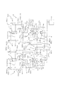
図3に、前記第1及び第2油圧ポンプユニット10,11の油圧回路図を示す。
前記第1油圧ポンプユニット10は、前記第1油圧モータユニット20との協働下に第1HSTを形成するように、油圧回路(本実施の形態においては、一対の第1作動油ライン30(1))を介して該第1油圧モータユニット20と流体接続されている。
さらに、前記第1油圧ポンプユニット10及び前記第1油圧モータユニット20の少なくとも一方は可変容積型とされている。
FIG. 3 shows a hydraulic circuit diagram of the first and second
The first
Furthermore, at least one of the first
同様に、前記第2油圧ポンプユニット11は、前記第2油圧モータユニット21との協働下に第2HSTを形成するように、油圧回路(本実施の形態においては、一対の第2作動油ライン30(2))を介して該第2油圧モータユニット21と流体接続されている。
そして、前記第2油圧ポンプユニット11及び前記第2モータユニット21の少なくとも一方は可変容積型とされている。
なお、本実施の形態においては、前記第1及び第2油圧ポンプユニット10,11が可変容積型とされ、且つ、前記第1及び第2油圧モータユニット20,21が固定容積型とされている。
Similarly, the second
At least one of the second
In the present embodiment, the first and second
以下、まず、第1油圧ポンプユニット10の構成について詳述する。
該第1油圧ポンプユニット10は、図1に示すように、車輌の仮想中央長手面Lを基準にして、車輌幅方向一方側(本実施の形態においては、車輌前方を向いた状態で右側)に配設されている。
なお、本実施の形態においては、該第1油圧ポンプユニット10は、回転軸線が略垂直方向に沿うように配設されている。
Hereinafter, first, the configuration of the first
As shown in FIG. 1, the first
In the present embodiment, the first
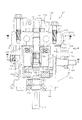
図4に、図2におけるIV-IV線に沿った前記第1油圧ポンプユニット10の縦断側面図を示す。又、図5に、図2におけるV-V線に沿った前記第1油圧ポンプユニット10の縦断背面図を示す。なお、図4中の符号F及びRは、それぞれ、車輌長手方向前方及び後方を示している。又、図5中の符号O及びIは、それぞれ、車輌幅方向外方及び内方を示している。
FIG. 4 is a longitudinal side view of the first
図4及び図5に示すように、前記第1油圧ポンプユニット10は、前記駆動源3に作動連結されるポンプ軸110と、該ポンプ軸110によって駆動されるポンプ本体120と、該ポンプ本体120に対して作動油を給排する一対の第1作動油路31(1)が形成された第1センターセクション130(1)と、前記ポンプ本体120を囲繞するように該第1センターセクション130(1)に連結されるポンプケース140とを備えている。
As shown in FIGS. 4 and 5, the first
前述の通り、本実施の形態においては、前記第1油圧ポンプユニット10は可変容積型とされている。
従って、前記第1ポンプユニット10は、前記構成に加えて、前記ポンプ本体120の吸引/吐出量を変化させる出力調整部材150と、該出力調整部材150を傾転させる制御軸160とを備えている。
本実施の形態においては、前記出力調整部材150として可動斜板が用いられ、前記制御軸160としてトラニオン軸が用いられている。
なお、本実施の形態においては、前記油タンク15との干渉を防止する為に、前記制御軸160は、車輌幅方向外方へ延在されている。
As described above, in the present embodiment, the first
Therefore, the
In the present embodiment, a movable swash plate is used as the
In the present embodiment, the
前記ポンプ軸110は、入力端部111が前記ポンプケース140及び前記第1センターセクション130Aが連結されてなるアッセンブリから外方へ延在するように、該アッセンブリに支持されている。
本実施の形態においては、前記入力端部111が前記アッセンブリから下方へ延在されている。
そして、該入力端部111は、適宜の伝動機構8(図示の形態においてはプーリー及びベルト)を介して、前記駆動源3に作動連結されている(図1及び図2参照)。
The
In the present embodiment, the
The
本実施の形態においては、前記ポンプ本体120は、前記ポンプ軸110の回転に伴って往復運動を行うピストンユニット121と、該ピストンユニット121を往復動自在に支持するシリンダブロック122とを有している。
In the present embodiment, the pump
前記第1センターセクション130(1)及び前記ポンプケース140は互いに連結されることにより、前記ポンプ本体120を収容するポンプ本体収容空間Sを形成するようになっている。
図6(a)に、図5におけるVI-VI線に沿った前記ポンプケース140の横断平面図を示す。又、図6(b)に、前記第2油圧ポンプユニット11におけるポンプケース140の横断平面図を示す。
なお、なお、図6中の符号F,R,O及びIは、それぞれ、車輌長手方向前方,車輌長手方向後方,車輌幅方向外方及び車輌幅方向内方を示している。
The first center section 130 (1) and the
FIG. 6A shows a cross-sectional plan view of the
It should be noted that symbols F, R, O, and I in FIG. 6 indicate the vehicle longitudinal direction front, the vehicle longitudinal direction rear, the vehicle width direction outer side, and the vehicle width direction inner side, respectively.
図4〜図6に示すように、前記ポンプケース140は、ポンプ軸方向一端側に位置する端壁141と、該端壁141からポンプ軸110の軸線方向他端側に延びる周壁142とを有している。
前記周壁142は、ポンプ軸110の軸線方向他端側が開口143となるように形成されている。該開口143は、前記ポンプ本体120が挿通可能な大きさとされている。
As shown in FIGS. 4 to 6, the
The
図6に示すように、本実施の形態において、前記周壁142は、前記ポンプ軸の軸線方向に沿って延びる4つの周面142a〜dを有している。
詳しくは、該4つの周面には、前記制御軸160の軸線と直交する方向に延び、該制御軸160を軸線回り回転自在に支持する支持孔165が形成された第1直交面142aと、前記ポンプ軸110を挟んで該第1直交面142aとは反対側に位置する第2直交面142bと、前記制御軸160の軸線方向と平行に延びる第1及び第2平行面142c、142dとが含まれる。
そして、前記第2直交面142b,前記第1及び第2平行面142c、142dには、それぞれ、前記ポンプ本体収容空間Sを外方に開口する貫通孔65が形成されている。
As shown in FIG. 6, in the present embodiment, the
Specifically, a first
The second
図7(a)に、図5におけるVII-VII線に沿った前記第1センターセクション130(1)の横断平面図を示す。又、図7(b)に、前記第2油圧ポンプユニット11における第2センターセクション130(2)の横断平面図を示す。
なお、図7中の符号F,R,O及びIは、それぞれ、車輌長手方向前方,車輌長手方向後方,車輌幅方向外方及び車輌幅方向内方を示している。
FIG. 7A shows a cross-sectional plan view of the first center section 130 (1) along the line VII-VII in FIG. FIG. 7B is a cross-sectional plan view of the second center section 130 (2) in the second
In addition, the codes F, R, O, and I in FIG. 7 indicate the vehicle longitudinal direction front, the vehicle longitudinal direction rear, the vehicle width direction outer side, and the vehicle width direction inner side, respectively.
前記第1センターセクション130(1)は、前記ポンプケース140との協働下に前記ポンプ本体120を回転可能に支持しつつ、前記開口143を閉塞するように、該ポンプケース140に連結される。
詳しくは、該第1センターセクション130(1)は、ポンプ軸110と直交する第1端面131であって、前記ポンプケース140と対向する第1端面131(本実施の形態においては、下面)を有している。
該第1端面131は、前記ポンプ本体120を回転自在に支持する支持領域131aと、該支持領域131aの径方向外方に位置する当接領域131bであって、前記ポンプケース140に当接される当接領域131bとを含む。
そして、前記第1センターセクション130(1)における第1端面131と前記ポンプケース140における周壁142の端面とを当接させることによって、前記ポンプ本体120を収容する前記ポンプ本体収容空間Sが画されるようになっている。
なお、該第1センターセクション130(1)及びポンプケース140のポンプ軸110回りの相対位置関係については後述する。
The first center section 130 (1) is coupled to the
Specifically, the first center section 130 (1) is a
The
The pump body housing space S for housing the
The relative positional relationship between the first center section 130 (1) and the
図3〜図5に示すように、本実施の形態においては、前記第1油圧ポンプユニット10は、さらに、チャージポンプユニット170を備えている。
該チャージポンプユニット170は、対応するポンプ軸110によって駆動されるチャージポンプ本体171と、該チャージポンプ本体171を囲繞するチャージポンプケース172とを有している。
As shown in FIGS. 3 to 5, in the present embodiment, the first
The
本実施の形態においては、前記チャージポンプユニット170は、前記センターセクション130における前記第1端面131とは反対側の第2端面132(本実施の形態においては上面)に連結されている。
詳しくは、前記ポンプ軸110は、前記入力端部111を構成する一端部が前記ポンプケース140の前記端壁141を貫通して外方へ延在されると共に、他端部112が前記第1センターセクション130Aを貫通して外方へ延在されている。
前記チャージポンプ本体171は前記ポンプ軸110の他端部112によって駆動されている。
なお、前記チャージポンプケース172は、前記チャージポンプ本体171を囲繞するように、前記第1センターセクション130(1)の第2端面132に連結されている。
In the present embodiment, the
Specifically, the
The
The
次に、前記第2油圧ポンプユニット11の構成について説明する。
該第2油圧ポンプユニット11は、前記仮想中央長手面Lを基準にして、前記第1油圧ポンプユニット10とは車輌幅方向反対側(本実施の形態においては、車輌前方を向いた状態で左側)に配設されている。
なお、本実施の形態においては、該第2油圧ポンプユニット11も、回転軸線が略垂直方向に沿うように配設されている。
Next, the configuration of the second
The second
In the present embodiment, the second
該第2油圧ポンプユニット11は、前記第1センターセクション130(1)を除き、前記第1油圧ポンプユニット10と実質的に同一構成を有している。
従って、前記第1油圧ポンプユニット11におけると同一部材には同一符号を付して、その説明を省略する。
The second
Therefore, the same members as those in the first
即ち、該第2油圧ポンプユニット11は、前記ポンプ軸110と、前記ポンプ本体120と、該ポンプ本体120に対して作動油を給排する一対の第2作動油路31(2)が形成された第2センターセクション130(2)(図7(b)参照)と、前記ポンプ本体120を囲繞するように該第2センターセクション130(2)に連結される前記ポンプケース140と、前記出力調整部材150と、前記制御軸160とを備えている。
又、該第2油圧ポンプユニット11は、前記第1油圧ポンプユニット10と同様、前記チャージポンプユニット170を備えている。
That is, the second
The second
ここで、前記第1及び第2センターセクション130(1),130(2)と対応する前記ポンプケース140との相対位置について説明する。
Here, the relative position between the first and second center sections 130 (1) and 130 (2) and the
図4,図6及び図7に示すように、前記第1及び第2センターセクション130(1),130(2)は、それぞれ、ボルト等の締結部材190を介して、対応する前記ポンプケース140に着脱可能に連結されている。
As shown in FIGS. 4, 6 and 7, the first and second center sections 130 (1) and 130 (2) are respectively connected to the
詳しくは、図6に示すように、前記ポンプケース140は、対応するポンプ軸110の軸線を基準にして非対称に配置された被連結部145を有している。
本実施の形態においては、該被連結部145には、ポンプ軸110の軸線方向に沿って視た際に、該ポンプ軸110の軸線を基準にして所定の同一半径R上に配設された基準被連結部145aと、該基準被連結部145aとは径方向に関し異なる位置に配設された変位被連結部145bとが含まれる。
例えば、前記基準被連結部145a及び前記変位被連結部145bは、前記周壁142における前記第1又は第2センターセクション130(1),130(2)との対向端面に開くように、該周壁142にポンプ軸110の軸線方向に沿って形成されたネジ付孔とされる。
Specifically, as shown in FIG. 6, the
In the present embodiment, the coupled portion 145 is disposed on a predetermined same radius R with respect to the axis of the
For example, the reference connected
なお、本実施の形態においては、前記基準被連結部145aと前記変位被連結部145bとをポンプ軸110の軸線を基準にして異なる半径上に配置することにより、該基準被連結部145a及び変位被連結部145bをポンプ軸110の軸線を基準にして非対称としたが、これに代えて、両被連結部を同一半径上に配し且つ周方向間隔を変えることも可能である。
In the present embodiment, the reference connected
前記第1センターセクション130(1)は、前記仮想中央長手面Lを基準にして車輌幅方向一方側(本実施の形態においては、車輌前方を向いた状態で右側)に配置され、且つ、前記一対の第1作動油路31(1)の開口端部が特定方向に向けられた状態において、対応する前記ポンプケース140が対応する前記ポンプ軸110回り第1相対位置に位置された場合にのみ該ポンプケース140と連結可能とされている。
The first center section 130 (1) is disposed on one side in the vehicle width direction with respect to the virtual central longitudinal surface L (in the present embodiment, on the right side in a state facing the front of the vehicle), and Only when the
詳しくは、図7に示すように、該第1センターセクション130(1)には、前述の通り、前記一対の第1作動油ライン(1)の一部を構成する一対の第1作動油路31(1)が形成されている。該一対の第1作動油路31(1)は、一端部が外方に開口して一対の第1作動油ポート30P(1)を形成し、且つ、他端部が前記ポンプ本体120における一対のキドニーポート120Pにそれぞれ連通されている。
斯かる構成の第1センターセクション130(1)において、前記第1作動油路31(1)の開口端部が特定方向に向けられた状態とは、
・前記一対の第1作動油ポート30P(1)が、第1油圧ポンプユニット10が図面に開示したようにその回転軸線を略垂直状とした車輌搭載形態にあっては、車輌前方,車輌後方,車輌幅方向内方又は車輌幅方向外方の何れか一の方向に向けられている状態を意味し、
・第1油圧ポンプユニット10がその回転軸線を略水平状とした車輌搭載形態にあっては、車輌上方,車輌下方,車輌幅方向内方又は車輌幅方向外方の何れか一の方向に向けられている状態を意味する。
Specifically, as shown in FIG. 7, the first center section 130 (1) includes a pair of first hydraulic oil passages that constitute a part of the pair of first hydraulic oil lines (1) as described above. 31 (1) is formed. The pair of first hydraulic oil passages 31 (1) have one end opened outward to form a pair of first
In the first center section 130 (1) having such a configuration, the state in which the opening end portion of the first hydraulic oil passage 31 (1) is directed in a specific direction is:
The pair of first
-When the first
なお、回転軸線が略垂直方向を向くように前記第1油圧ポンプユニット10が車輌に搭載されている本実施の形態においては、前記一対の第1作動油ポート30P(1)が車輌前後方向後方を向く方向を前記特定方向としている(図7参照)。
これに代えて、前記一対の第1作動油ポート30P(1)を車輌前後方向前方や車輌幅方向内方又は外方へ向けることも可能である。
又、第1油圧ポンプユニット10の回転軸線を略水平状とした車輌搭載形態にあっては、前記一対の第1作動油ポート30P(1)が車輌上方,車輌下方,車輌幅方向内方又は車輌幅方向外方の何れかを向く方向を前記特定方向とすることも可能である。
In the present embodiment in which the first
Alternatively, the pair of first
Further, in the vehicle mounting configuration in which the rotation axis of the first
該第1センターセクション130(1)は、斯かる特定方向に向かされた状態において、前記ポンプケース140がポンプ軸110の軸線回り第1相対位置に位置された場合にのみ該ポンプケース140と連結可能とされている。
具体的には、該第1センターセクション130(1)は、前記ポンプ軸110の軸線を基準にして非対称に配置された第1連結部135(1)であって、前記ポンプケース140が第1相対位置に位置された際に該ポンプケース140に形成された被連結部145に対応する第1連結部135(1)を有している。
The first center section 130 (1) is in the state of being directed in such a specific direction only when the
Specifically, the first center section 130 (1) is a first connecting portion 135 (1) disposed asymmetrically with respect to the axis of the
図8に、前記第1油圧ポンプユニット10を、ポンプ軸110の軸線に沿ってチャージポンプユニット170の側から視た端面図を示す。
図7及び図8に示すように、該第1連結部135(1)は、前記第1センターセクション130(1)が車輌幅方向一方側において前記特定方向に向かされ、且つ、対応するポンプケース140がポンプ軸回り第1相対位置に位置された状態において、前記被連結部145(1)と連結可能に配置されている。
本実施の形態においては、ポンプケース140の第1相対位置とは、該第1油圧ポンプユニット10が前記仮想中央長手面Lを基準にして車輌幅方向一方側で且つ回転軸線を略垂直方向に沿わせて配設された状態において、前記制御軸160を支持する前記第1直交面142aが車輌幅方向外方を向く位置を意味する。
FIG. 8 shows an end view of the first
As shown in FIGS. 7 and 8, the first connecting portion 135 (1) has the first center section 130 (1) directed in the specific direction on one side in the vehicle width direction, and a corresponding pump. In a state where the
In the present embodiment, the first relative position of the
具体的には、該第1連結部135(1)には、前記ポンプケース140が第1相対位置に位置された際に、前記基準被連結部145aに対応した位置に配設される第1基準連結部135(1)aと、前記変位連結部145bに対応した位置に配設される第1変位連結部135(1)bとが含まれている。
例えば、前記第1基準連結部135(1)a及び前記第1変位連結部135(1)bは、前記第1端面131及び第2端面132を貫通するように、ポンプ軸110の軸線方向に沿って形成されたネジ無し貫通孔とされる。
Specifically, the first connecting portion 135 (1) is disposed at a position corresponding to the reference connected
For example, the first reference connecting portion 135 (1) a and the first displacement connecting portion 135 (1) b are arranged in the axial direction of the
又、本実施の形態においては、前記第1直交面142aが車輌幅方向外方を向く状態を前記ポンプケース140の第1相対位置としたが、これに代えて、該第1直交面142aが車輌幅方向内方や車輌前後方向の何れかの方向を向く状態を第1相対位置とすることも可能である。
さらに、回転軸線が略水平方向に沿うように前記第1油圧ポンプユニット10が車輌に搭載される場合には、前記第1直交面142aが車輌幅方向外方,車輌幅方向内方,上方,又は下方の何れかの方向を向く状態を、前記第1相対位置とすることも可能である。
In the present embodiment, the state in which the first
Further, when the first
これに対し、前記第2センターセクション130(2)は、前記第2油圧ポンプユニット11が前記仮想中央長手面Lを基準にして車輌幅方向他方側(本実施の形態においては、車輌前方を向いた状態で左側)において回転軸線を略垂直方向に沿わせて配置され、且つ、前記一対の第2作動油路31(2)の開口端部(第2作動油ポート30P(2))が前記仮想中央長手面を基準にして前記第1作動油ポート30P(1)と同一方向に向けられた状態で、対応するポンプケース140が第2相対位置に位置する場合にのみ該ポンプケース140と連結可能とされている。
On the other hand, the second center section 130 (2) is configured such that the second
即ち、図7に示すように、前記第2センターセクション130(2)には、前記第1センターセクション130(1)と同様、一端部が外方に開口して一対の第2作動油ポート30P(2)を形成し、且つ、他端部が前記ポンプ本体120における一対のキドニーポート120Pにそれぞれ連通された一対の第2作動油路31(2)が形成されている。
本実施の形態においては、斯かる構成の該第2センターセクション130(2)は、前記第2作動油ポート30P(2)が仮想中央長手面Lを基準にして前記第1作動油ポート30P(1)と同一方向を向くように、配置されている。
That is, as shown in FIG. 7, the second center section 130 (2) has one end opened outwardly and a pair of second
In the present embodiment, in the second center section 130 (2) having such a configuration, the second
なお、仮想中央長手面Lを基準にして同一方向とは、前記第1作動油ポート30P(1)が車輌前後方向後方を向く場合には前記第2作動油ポート30P(2)も車輌前後方向後方を向き、前記第1作動油ポート30P(1)が車輌幅方向内方を向く場合には前記第2作動油ポート30P(2)も車輌幅方向内方を向き、且つ、前記第1作動油ポート30P(1)が車輌幅方向外方を向く場合には前記第2作動油ポート30P(2)も車輌幅方向外方を向くことを意味する。
The same direction with reference to the virtual central longitudinal surface L means that when the first
斯かる第2センターセクション130(2)は、前述の通り、仮想中央長手面Lを基準にして前記第1センターセクション130(1)と同一方向を向く状態において、対応する前記ポンプケース140がポンプ軸110の軸線回り第2相対位置に位置された場合のみ該ポンプケース140と連結可能とされている。
As described above, the second center section 130 (2) has the
具体的には、該第2センターセクション130(2)は、第2連結部135(2)を有している。
該第2連結部135(2)は、該第2センターセクション130(2)が車輌幅方向他方側において仮想中央長手面Lを基準にして前記第1センターセクション130(1)と同一方向に配置され、且つ、対応するポンプケース140がポンプ軸110の軸線回り第2相対位置に位置された状態においてのみ、該対応するポンプケース140の前記被連結部145と連結可能に配置されている。
Specifically, the second center section 130 (2) has a second connecting portion 135 (2).
The second connecting portion 135 (2) is arranged in the same direction as the first center section 130 (1) with the second center section 130 (2) on the other side in the vehicle width direction with respect to the virtual central longitudinal surface L. In addition, only when the
なお、前記第2センターセクション130(2)に連結されるポンプケース140の第2相対位置とは、該ポンプケース140の第1直交面142aが前記第1センターセクション130(1)に連結されるポンプケース140の第1直交面142aと仮想中央長手面Lを基準にして同一方向を向く位置を意味している。
The second relative position of the
即ち、回転軸線が略垂直方向に沿うように前記第1油圧ポンプユニット10が車輌に搭載される態様において、前記第1センターセクション130(1)に連結される前記ポンプケース140の第1直交面142aが車輌幅方向外方,車輌幅方向内方,車輌前方又は車輌後方を向く姿勢を、それぞれ、該ポンプケース140の第1相対位置とする場合、前記第2センターセクション130(2)に連結されるポンプケース140の第2相対位置とは、該ポンプケース140の第1直交面142aがそれぞれ車輌幅方向外方,車輌幅方向内方,車輌前方又は車輌後方を向く姿勢を意味する。
これに代えて、回転軸線が略水平方向に沿うように前記第1油圧ポンプユニット10が車輌に搭載される態様において、前記第1センターセクション130(1)に連結される前記ポンプケース140の第1直交面142aが車輌幅方向外方,車輌幅方向内方,上方又は下方を向く姿勢を、それぞれ、該ポンプケース140の第1相対位置とする場合、前記第2センターセクション130(2)に連結されるポンプケース140の第2相対位置とは、該ポンプケース140の第1直交面142aがそれぞれ車輌幅方向外方,車輌幅方向内方,上方又は下方を向く姿勢を意味する。
That is, in the aspect in which the first
Instead, in a mode in which the first
なお、本実施の形態においては、前述の通り、前記第1センターセクション130(1)に連結されるポンプケース140の第1相対位置とは、仮想中央長手面Lを基準にして車輌幅方向一方側に配置された状態において、第1直交面142aが車輌幅方向外方を向く位置を意味している。
従って、前記第2センターセクション130(2)に連結されるポンプケース140にとっては、仮想中央長手面Lを基準にして車輌幅方向他方側に配置された状態において、第1直交面142aが車輌幅方向外方を向く位置が第2相対位置となる。
In the present embodiment, as described above, the first relative position of the
Therefore, for the
斯かる構成の油圧ポンプセット100Aにおいては、以下の効果を得ることができる。
前記第1及び第2油圧ポンプユニット10,11は、前述の通り、センターセクションを除き、部品が共通化されている。
即ち、本実施の形態に係る油圧ポンプセット100Aは、前記ポンプ本体120,前記ポンプケース140及び前記ポンプ軸110が共通部品とされている。
従って、これらの共通部品の製造コストや管理コストの低廉化を図ることができる。
In the hydraulic pump set 100A having such a configuration, the following effects can be obtained.
As described above, the first and second
That is, in the hydraulic pump set 100A according to the present embodiment, the
Therefore, the manufacturing cost and management cost of these common parts can be reduced.
さらに、本実施の形態においては、前記第1センターセクション130(1)は、対応するポンプケース140がポンプ軸110の軸線回り第1相対位置に位置する場合にのみ該ポンプケース140と連結可能とされている。
同様に、前記第2センターセクション130(2)は、対応するポンプケース140がポンプ軸110の軸線回り第2相対位置に位置する場合にのみ該ポンプケース140と連結可能とされている。
斯かる構成においては、ポンプケース140における第1直交面142aと、各センターセクション130(1),130(2)における作動油ポート30P(1),30P(2)との相対位置は、必ず固定されることになる。
従って、油圧機器メーカにおいて、センターセクションとポンプケースとの相対位置を間違えて両者を連結する不都合が有効に防止される。
さらに、両者の相対位置に注意しながら組立作業を行う必要が無い為、センターセクション及びポンプケースの組立作業効率を向上させることができ、これにより、正確に組み立てられた左用と右用の油圧ポンプユニット10、11を車両製造メーカへ供給できる。
Further, in the present embodiment, the first center section 130 (1) can be connected to the
Similarly, the second center section 130 (2) can be connected to the
In such a configuration, the relative positions of the first
Therefore, in the hydraulic equipment manufacturer, it is possible to effectively prevent the inconvenience of connecting the center section and the pump case in the wrong relative positions.
Furthermore, since it is not necessary to perform assembly work while paying attention to the relative positions of the two, it is possible to improve the assembly work efficiency of the center section and the pump case, so that the left and right hydraulic pumps assembled correctly can be improved.
ここで、前記第1及び前記第2油圧ポンプユニット10,11の油圧回路について、第1油圧ポンプユニット10を中心に説明する。
なお、前記第2油圧ポンプユニット11の油圧回路は、実質的に該第1油圧ポンプユニット10の油圧回路と同一である。従って、図中、同一部材又は相当部材には同一符号に(2)を付している。
Here, the hydraulic circuit of the first and second
The hydraulic circuit of the second
図3に示すように、前記第1油圧ポンプユニット10は、対応する第1油圧モータユニット20との間を流体接続する前記一対の第1作動油ライン30(1)と、一端部が油タンク15に流体接続され且つ他端部が前記一対の作動油ライン30(1)のそれぞれに流体接続されたチャージライン50(1)と、一端部が前記ポンプ本体収容空間Sに連通され且つ他端部が前記油タンク15に連通されたドレンライン60(1)とを有している。
As shown in FIG. 3, the first
図3及び図7に示すように、前記一対の作動油ライン30(1)は、前記第1センターセクション130(1)に穿孔された前記一対の第1作動油路31(1)と、該一対の第1作動油路31(1)のそれぞれを前記第1油圧モータユニット20に連通する一対の作動油配管32(図1及び図2参照)とを有している。
As shown in FIGS. 3 and 7, the pair of hydraulic oil lines 30 (1) includes the pair of first hydraulic oil passages 31 (1) perforated in the first center section 130 (1), Each of the pair of first hydraulic oil passages 31 (1) has a pair of hydraulic oil pipes 32 (see FIGS. 1 and 2) that communicate with the first
図9(a)に、図4におけるIX-IX線に沿った前記第1油圧ポンプユニット10におけるチャージポンプケース172の横断平面図を示す。又、図9(b)に、前記第2油圧ポンプユニット11におけるチャージポンプケース172の横断面図を示す。
FIG. 9A shows a cross-sectional plan view of the
前記チャージライン50(1)は、図3に示すように、一端部が前記油タンク15に連通されたチャージ配管51と、一端部が前記アッセンブリの外面に開口されてチャージサクションポート50P(1)を形成し且つ他端部が前記一対の作動油ライン30(1)のそれぞれに連通されたチャージ油路52(1)とを有している。
As shown in FIG. 3, the charge line 50 (1) has a
同様に、前記第2油圧ポンプユニットにおけるチャージライン50(2)も、一端部が前記油タンク15に連通されたチャージ配管51と、一端部が前記アッセンブリの外面に開口されてチャージサクションポート50P(2)を形成し且つ他端部が対応する一対の作動油ライン30(2)のそれぞれに連通されたチャージ油路52(2)とを有している。
Similarly, the charge line 50 (2) in the second hydraulic pump unit also has a
本実施の形態において、前記チャージ油路52(1)は、前記チャージポンプケース172に形成された第1チャージ油路53と、前記第1センターセクション130(1)に形成された第2チャージ油路54(1)とを有している。
同様に、前記チャージ油路52(2)は、前記チャージポンプケース172に形成された第1チャージ油路53と、前記第2センターセクション130(2)に形成された第2チャージ油路54(2)とを有している。
In the present embodiment, the charge oil passage 52 (1) includes a first
Similarly, the charge oil passage 52 (2) includes a first
即ち、前記第1チャージ油路53は、一端部が前記チャージサクションポート50P(1)又は50P(2)を形成するように前記チャージポンプケース172の外面に開口し、且つ、他端部が対応する第1又は第2センターセクション130(1),130(2)との当接面172aに開口している。
そして、前記第1及び第2センターセクション130(1),130(2)は共に、対応する前記チャージポンプケース140を、それぞれのチャージサクションポート50P(1),50P(2)が前記仮想中央長手面Lを基準にして同一方向を向くように、支持可能とされている。
That is, the first
The first and second center sections 130 (1) and 130 (2) are both connected to the corresponding
本実施の形態においては、前記第1センターセクション130(1)は、前記第1作動油ポートが車輌後方を向くように配置された状態で、前記チャージサクションポート50P(1)が車輌前方を向くように、対応するチャージポンプケース172を支持し得るようになっている。
又、前記第2センターセクション130(2)は、前記第2作動油ポート30P(2)が前記仮想中央長手面Lを基準にして前記第1作動油ポート30P(1)と同一方向を向くように配置された状態で、前記チャージサクションポート50P(2)が車輌前方を向くように、対応するチャージポンプケース172を支持し得るようになっている。
In the present embodiment, the first center section 130 (1) is arranged such that the first hydraulic oil port faces the rear of the vehicle, and the
The second center section 130 (2) is configured such that the second
このように、各ポンプユニット10,11において、作動油ポート30Pとチャージサクションポート50Pとを反対方向に向けることにより、作動油配管32とチャージ配管51との干渉を有効に防止できる。
As described above, in each
なお、本実施の形態においては、前記第1チャージ油路53に前記チャージポンプ本体171が介挿されている。
さらに、前記チャージポンプケース172には、前記チャージポンプ本体171を挟んで、チャージ油の流れ方向前流側及び後流側を接続するチャージ圧設定ライン55が形成されている。該チャージ圧設定ライン55には、リリーフ弁56が介挿されている。
In the present embodiment, the
Further, the
前記第2チャージ油路54は、一端部が、前記第1チャージ油路53の他端部に連通するように、前記センターセクション130の第2端面132に開口し、且つ、他端部が、前記一対の作動油路31にそれぞれ連通されている。
前記第2チャージ油路54(1),54(2)は、一端部が、対応する前記第1チャージ油路53(1),53(2)の他端部に連通するように第2端面132に開口し、且つ、他端部が、対応する前記一対の作動油路31(1),31(2)に連通するように、前記第1及び第2センターセクション130(1),130(2)に形成されている。
The second
The second charge oil passages 54 (1), 54 (2) have second end faces so that one end portions thereof communicate with the other end portions of the corresponding first charge oil passages 53 (1), 53 (2). The first and second center sections 130 (1), 130 (130 (1), 130 (1), 130 (2) are opened so that the other end communicates with the corresponding pair of hydraulic oil passages 31 (1), 31 (2). Formed in 2).
詳しくは、前記第1油圧ポンプユニット10における第2チャージ油路54(1)は、前記第1チャージ油路53(1)に連通された共通チャージ油路40(1)と、分岐点Cにおいて該共通チャージ油路40(1)から分岐され且つ前記一対の作動油路31(1)にそれぞれ連通された一対の分岐油路41(1)とを有している(図3及び図6参照)。
同様に、前記第2油圧ポンプユニット11における第2チャージ油路54(2)は、前記第1チャージ油路53(2)に連通された共通チャージ油路40(2)と、分岐点Cにおいて該共通チャージ油路40(2)から分岐され且つ前記一対の作動油路31(2)にそれぞれ連通された一対の分岐油路41(2)とを有している(図3及び図6参照)。
Specifically, the second charge oil passage 54 (1) in the first
Similarly, the second charge oil passage 54 (2) in the second
前記一対の分岐油路41(1),41(2)には、それぞれ、チェック弁42が設けられている。
該チェック弁42は、前記チャージライン50から前記一対の作動油ライン30(1),30(2)への圧油の流入を許容し、且つ、逆向きの圧油の流れを防止する為に備えられる。
なお、本実施の形態においては、該チェック弁42は絞り43(図3参照)を有しており、厳格な出力調整部材150の制御を要すること無く、HSTの中立状態を得られるようになっている。
A
The
In the present embodiment, the
図7に示すように、本実施の形態においては、前記一対の分岐油路41(1)は、対応する前記一対の作動油路31(1)の間を連通するように該一対の作動油路31(1)と略直交する方向に延びている。
即ち、該一対の分岐油路41(1)は、前記一対の作動油路31(1)を連通する単一の油路として形成されており、該単一油路に対して前記共通チャージ油路40(1)が前記分岐点Cにおいて連通されている。
斯かる構成を備えることにより、前記一対の分岐油路41(1)を効率的に配置させることができる。
As shown in FIG. 7, in this embodiment, the pair of branch oil passages 41 (1) communicates between the pair of hydraulic oil passages 31 (1) so as to communicate with each other. It extends in a direction substantially orthogonal to the path 31 (1).
That is, the pair of branch oil passages 41 (1) are formed as a single oil passage that communicates with the pair of hydraulic oil passages 31 (1), and the common charge oil is connected to the single oil passage. The path 40 (1) is communicated at the branch point C.
By providing such a configuration, the pair of branch oil passages 41 (1) can be efficiently arranged.
前記ドレンライン60(1),60(2)は、対応する前記ポンプ本体収容空間Sを外方に連通するドレンポート60P(1),60P(2)と、一端部が該ドレンポート60P(1),60P(2)に連通され且つ他端部が前記油タンク15に連通されたドレン配管62とを有している。
The drain lines 60 (1), 60 (2) have
図4及び図6に示すように、本実施の形態においては、前記ドレンポート60P(1),60P(2)は対応する前記ポンプケース140に形成されている。
前述の通り、ポンプケース140には、前記第1直交面142a以外の周面にそれぞれ貫通孔65が形成されている(図6等参照)。
As shown in FIGS. 4 and 6, in the present embodiment, the
As described above, the
前記第1油圧ポンプユニット10におけるポンプケース140は、前記第1相対位置におかれた状態で、車輌前方を向く周面(第1平行面142c)に形成された貫通孔65を前記ドレンポート60P(1)として使用している(図6(a)参照)。
これに対し、前記第2油圧ポンプユニット11におけるポンプケース140は、前記第2相対位置におかれた状態で、車輌前方を向く周面(第2平行面142d)に形成された貫通孔65を前記ドレンポート60P(2)として使用している(図6(b))。
そして、両ポンプケース140において、使用しない貫通孔65はプラグ66で閉塞されている。
The
On the other hand, the
In both
このように、本実施の形態においては、ポンプケース140が第1相対位置に置かれた際及び第2相対位置に置かれた際にドレンポート60P(1),60P(2)が同一方向を向くように、該ポンプケース140に少なくとも2つの開口65を設けている。
従って、第1及び第2油圧ポンプユニット10,11におけるドレンライン60(1),60(2)を効率的に前記油タンク15へ接続させることができる。
Thus, in the present embodiment, when the
Therefore, the drain lines 60 (1), 60 (2) in the first and second
なお、本実施の形態においては、前記第1及び第2油圧ポンプユニット10,11における各ドレンポート60P(1),60P(2)が車輌前後方向前方を向くように構成したが、当然ながら、本発明は斯かる形態に限定されるものではない。
即ち、前記両ドレンポート60P(1),60P(2)が前記仮想中央長手面Lを基準にして同一方向を向く限り、種々の形態が適用可能である。例えば、両ドレンポート60P(1),60P(2)が車輌前後方向後方を向くように構成することも可能であるし、両ドレンポート60P(1),60P(2)が車輌幅方向内方を向くように構成すること、若しくは、車輌幅方向外方を向くように構成することも可能である。また、第1及び第2油圧ポンプユニット10,11がその回転軸線を略水平状として搭載される態様においては、両ドレンポート「60P(1),60P(2)が車輌上下方向の何れかを向くように構成することも可能である。
In the present embodiment, the
That is, as long as both the
さらに、前記第1及び第2油圧ポンプユニット10,11は、前記一対の第1及び第2作動油ライン30(1),30(2)の間を連通するバイパスライン70(1),70(2)を有している。
該バイパスライン70(1)は、故障時等において、車輌を強制的に牽引する際に、前記一対の第1作動油ライン30(1)の間に圧力差が生じることを防止する為に備えられる。
なお、バイパスライン70(2)は、バイパスライン70(1)と実質的に同一構成を有している。従って、バイパスライン70(2)の説明は省略する。
Further, the first and second
The bypass line 70 (1) is provided to prevent a pressure difference from being generated between the pair of first hydraulic oil lines 30 (1) when the vehicle is forcibly pulled in the event of a failure or the like. It is done.
The bypass line 70 (2) has substantially the same configuration as the bypass line 70 (1). Therefore, the description of the bypass line 70 (2) is omitted.
本実施の形態においては、前記バイパスライン70(1)は、前記一対の第1作動油路31(1)の間を連通するように、前記第1センターセクションに形成されたバイパス油路71(1)と、該バイパス油路71(1)を選択的に連通/遮断させる切換弁72とを有している。
In the present embodiment, the bypass line 70 (1) is connected to the bypass oil passage 71 (1) formed in the first center section so as to communicate between the pair of first hydraulic oil passages 31 (1). 1) and a switching
前記バイパス油路71(1)は、前記ポンプ軸110を挟んで、前記一対の分岐油路41(1)を構成する前記単一油路とは反対側に位置されている。
即ち、本実施の形態においては、図7に示すように、前記第1作動油路31(1)は、内端部がポンプ軸110を基準にして作動油ポート30P(1)とは反対側の領域まで延びている。
そして、前記一対の分岐油路41(1)を構成する前記単一油路及び前記バイパス油路71(1)は、前記ポンプ軸110を挟んで振り分け配置されており(図7参照)、これにより、一対の作動油路31(1),前記一対の分岐油路41(1)及び補助バイパス油路71(1)の効率的な配置を実現している。
The bypass oil passage 71 (1) is located on the opposite side of the single oil passage constituting the pair of branch oil passages 41 (1) with the
That is, in the present embodiment, as shown in FIG. 7, the first hydraulic oil passage 31 (1) has an inner end opposite to the
The single oil passage and the bypass oil passage 71 (1) constituting the pair of branch oil passages 41 (1) are arranged with the
前記第1及び第2センターセクション130(1),130(2)におけるバイパス油路71(1),71(2)は共に一端部が外方に開口されており、該開口端部から前記切換弁72が操作可能とされているが、好ましくは、それぞれの開口端部が前記仮想中央長手面Lを基準にして同一方向を向くものとされている。
本実施の形態においては、前記第1及び第2センターセクション130(1),130(2)における各バイパス油路71(1),71(2)は、それぞれの開口端部が車輌幅方向外方を向くように形成されている。
The bypass oil passages 71 (1) and 71 (2) in the first and second center sections 130 (1) and 130 (2) are both open at one end, and the switching is performed from the open end. The
In the present embodiment, the bypass oil passages 71 (1) and 71 (2) in the first and second center sections 130 (1) and 130 (2) have their respective open ends outside the vehicle width direction. It is formed to face the direction.
実施の形態2.
以下、本発明の係る油圧ポンプユニットの第2の実施の形態について、添付図面を参照しつつ説明する。
なお、本実施の形態において、前記実施の形態1におけると同一又は相当部材には同一符号又は同一符号に(B)を付して、その詳細な説明を省略する。
Hereinafter, a second embodiment of a hydraulic pump unit according to the present invention will be described with reference to the accompanying drawings.
In the present embodiment, the same or corresponding members as those in the first embodiment are denoted by the same reference numerals or the same reference numerals, and detailed description thereof is omitted.
図10に、本実施の形態に係る油圧ポンプユニット100Bが適用された作業車輌1Bの部分平面図を示す。又、図11に該油圧ポンプセット100Bの油圧回路図を示す。
さらに、図12に、図10におけるXII-XII線断面図を示す。又、図13(a)に、図12におけるXIII-XIII線断面図であって、第1センターセクション130B(1)の横断平面図を示す。又、図13(b)に、第2センターセクション130B(2)の横断平面図を示す。
なお、図12及び図13は、それぞれ、前記実施の形態1における図4及び図7に対応している。
FIG. 10 shows a partial plan view of a working vehicle 1B to which the
Further, FIG. 12 shows a cross-sectional view taken along line XII-XII in FIG. FIG. 13 (a) is a cross-sectional view taken along line XIII-XIII in FIG. 12, and shows a cross-sectional plan view of the
12 and 13 correspond to FIGS. 4 and 7 in the first embodiment, respectively.
図10〜図13に示すように、本実施の形態に係る油圧ポンプセット100Bは、基準面(本実施の形態においては、仮想中央基準面L)を挟んで略対称に配設された第1油圧ポンプユニット10B及び第2油圧ポンプユニット11Bを備えている。
該第1及び第2油圧ポンプユニット10B,11Bは、それぞれ、前記第1及び第2油圧ポンプユニット10,11において、前記チャージポンプユニット170に代えて冷却ファン180を有している。
なお、本実施の形態においても、前記実施の形態1におけると同様、第1及び第2油圧ポンプユニット10B,11Bは、回転軸線が略垂直方向に沿うように車輌に搭載されている。
As shown in FIGS. 10 to 13, the hydraulic pump set 100 </ b> B according to the present embodiment has a first symmetrical arrangement with a reference plane (in this embodiment, a virtual central reference plane L) interposed therebetween. A
The first and second
In the present embodiment as well, as in the first embodiment, the first and second
このように、チャージポンプユニット170の代わりに前記冷却ファン180を備えたことにより、本実施の形態においては、前記チャージサクションポート50P(1),50P(2)が第1及び第2センターセクション130B(1),130B(2)に設けられている(図13参照)。
即ち、前記実施の形態1においては、前記チャージポンプユニット170によって強制的にチャージ油を吸引していたが、本実施の形態においては、チャージ油を自然吸引するように構成されている。
Thus, by providing the cooling
That is, in the first embodiment, the charge oil is forcibly sucked by the
具体的には、前記第1油圧ポンプユニット10B(1)におけるチャージライン50B(1)は、図11に示すように、前記チャージ配管51と、前記第1センターセクション130B(1)に形成された第1チャージ油路54B(1)とを有している。
Specifically, the
前記第1チャージ油路54B(1)は、図13に示すように、一端部が前記第1センターセクション130B(1)の外側面に開口してチャージサクションポート50P(1)を形成し、且つ、他端部が前記一対の作動油路31(1)のそれぞれにに連通するように、該第1センターセクション130B(1)に形成されている。
As shown in FIG. 13, the first
より詳しくは、前記第1チャージ油路54B(1)は、前記チャージサクションポート50P(1)を形成する共通チャージ油路40(1)と、分岐点Cにおいて該共通チャージ油路40(1)から分岐された一対の分岐油路41(1)であって、前記一対の作動油路31(1)のそれぞれに連通された一対の分岐油路41(1)とを有している。
本実施の形態においては、図13に示すように、対応するポンプ軸110を挟んで前記第1作動油ポート30P(1)とは反対側の領域において、前記一対の第1作動油路31(1)の間を連通する単一油路が、前記一対の分岐油路41(1)を構成するようになっている。
斯かる構成を備えることにより、前記チャージサクションポート50P(1)を前記第1作動油ポート30P(1)とは反対側に容易に位置させることができ、作動油配管32とチャージ配管51との干渉を防止することができる。
なお、本実施の形態において、前記バイパス油路71(1)は、前記ポンプ軸110を挟んで前記一対の分岐油路41(1)と反対側(即ち、作動油ポート30P(1)に近接する側)に配置されている。
More specifically, the first
In the present embodiment, as shown in FIG. 13, the pair of first hydraulic oil passages 31 (in the region opposite to the first
With such a configuration, the
In the present embodiment, the bypass oil passage 71 (1) is opposite to the pair of branch oil passages 41 (1) across the pump shaft 110 (ie, close to the
斯かる構成の作業車輌においても、前記実施の形態1及び2におけると同様の効果を得ることができる。
なお、前記各実施の形態においては、ドレンポート60P(1),60P(2)をポンプケース140に設けたが、これに代えて、ドレンポート60P(1),60P(2)をセンターセクション130,130B又はチャージポンプケース172に設けることも可能である。
Also in the working vehicle having such a configuration, the same effect as in the first and second embodiments can be obtained.
In each of the above embodiments, the
実施の形態3
以下、本発明に係る油圧ポンプセットの第3の実施の形態につき、添付図面を参照しつつ説明する。
図14及び図15に、それぞれ、本実施の形態に係る油圧ポンプセットにおけるポンプケース140C及びセンターセクション130Cの横断平面図を示す。図14及び図15は、それぞれ、前記実施の形態1における図6及び図7に対応している。
又、図16に、該油圧ポンプセットにおける油圧ポンプユニット10Cの端面図であって、ポンプ軸110の軸線に沿ってチャージポンプユニット170の側から視た端面図を示す。該図16は、前記実施の形態1における図8に対応する。
なお、前記各実施の形態1,2におけると同一又は相当部材は同一符号を付して、その詳細な説明を省略する。
Embodiment 3
Hereinafter, a third embodiment of a hydraulic pump set according to the present invention will be described with reference to the accompanying drawings.
14 and 15 show cross-sectional plan views of the
FIG. 16 is an end view of the
The same or corresponding members as those in the first and second embodiments are given the same reference numerals, and detailed description thereof is omitted.
図14〜図16に示すように、本実施の形態に係る油圧ポンプセットは、一対の共通油圧ポンプユニット10Cを備えている。
即ち、前記各実施の形態1,2においては、第1及び第2油圧ポンプユニットが異なるセンターセクションを有するものとしたが、本実施の形態においては、全て同一構成とされている。
As shown in FIGS. 14 to 16, the hydraulic pump set according to the present embodiment includes a pair of common
That is, in each of the first and second embodiments, the first and second hydraulic pump units have different center sections, but in this embodiment, all have the same configuration.
詳しくは、該油圧ポンプユニット10Cは、前記ポンプ本体120と、前記ポンプ本体120を支持可能なセンターセクション130Cと、前記ポンプ本体120を収容するように、前記センターセクション130Cに着脱可能に連結されるポンプケース140Cと、前記ポンプ軸110と、前記制御軸160とを備えている。
Specifically, the
前記センターセクション130Cは、図15に示すように、前記ポンプケース140Cが連結された状態において、前記制御軸160に対して直交する方向に延びる一対の作動油路31Cを有している。
該一対の作動油路31Cはポンプ軸110を挟んで振り分け配置されている。
さらに、該一対の作動油路31Cは、一端部31C(1)及び他端部31C(2)がそれぞれ外方に開いて作動油ポート30P(1),30P(2)を形成し得るように構成されている。
As shown in FIG. 15, the
The pair of
Further, the pair of
即ち、本実施の形態においては、図14及び図15に示すように、前記センターセクション130C及び前記ポンプケース140Cが連結されてなるアッセンブリを、ポンプ軸110回りに180度回転させても、両端部31C(1),31C(2)が開口端部とされた前記一対の作動油路31Cは同一方向を向く。
That is, in the present embodiment, as shown in FIGS. 14 and 15, both ends of the assembly formed by connecting the
斯かる構成によれば、仮想中央長手面Lを基準にして車輌幅方向一方側(図示の形態では、車輌前方を向いた状態で右側)において、前記制御軸160が車輌幅方向外方を向くように一のアッセンブリを配置すると共に(図15(a)参照)、他のアッセンブリを該一のアッセンブリに対してポンプ軸回り180度回転させた状態で、仮想中央長手面Lを基準にして車輌幅方向他方側(図示の形態では、車輌前方を向いた状態で左側)に配置することにより、各制御軸160及び各作動油路31Cは仮想中央長手面Lを基準にして同一方向を向くことになる。
従って、前記一のアッセンブリにおいては、前記一対の作動油路31Cの一端部31C(1)を作動油ポート30P(1)として用い、且つ、前記他のアッセンブリにおいては、前記一対の作動油路31Cの他端部31C(2)を作動油ポート30P(2)として用いることにより、略対称に配置される一対のポンプユニット10Cの一方の作動油ポート30P(1)と他方の作動油ポート30P(2)とを同一方向へ向けることができる。
なお、作動油ポート30P(1),30P(2)として用いない開口端部は、プラグ35によって閉塞される。
According to such a configuration, the
Accordingly, in the one assembly, one
Note that the open ends that are not used as the
斯かる構成の本実施の形態においては、油圧機器メーカにおいて、センターセクション130C及びポンプケース140Cを連結するに際し、一対の作動油路31Cが制御軸160と直交するように両者を連結するだけで良く、車輌フレーム2への配置を考慮する必要がない。
従って、油圧ポンプユニット10Cの組立ミスを防止して、組立作業効率を向上させることができる。
In the present embodiment having such a configuration, when the hydraulic equipment manufacturer connects the
Therefore, assembly errors of the
なお、本実施の形態においては、一対の作動油路31Cの向きと制御軸160の向きとを間違えずにセンターセクション130C及びポンプケース140Cを連結させる為に、該センターセクション130Cの被連結部135(1)a及びポンプケース140の連結部145aは、前記一対の作動油路と平行な方向のピッチm及び直交する方向のピッチnを異ならせている。
In the present embodiment, in order to connect the
さらに、前記センターセクション130Cは、前記実施の形態1におけると同様、チャージ油路の一部を形成する前記一対の分岐油路41(1)と、前記バイパス油路71(1)とを有している。
図15に示すように、該一対の分岐油路41(1)及びバイパス油路71(1)は、ポンプ軸110を挟んで振り分け配置されており、これにより、センターセクション130Cの小型化を図っている。
Further, as in the first embodiment, the
As shown in FIG. 15, the pair of branch oil passages 41 (1) and bypass oil passages 71 (1) are arranged so as to sandwich the
なお、仮想中央長手面Lを基準にして一方側に配置される油圧ポンプユニット10C(図15(a)参照)と、他方側に配置される油圧ポンプユニット10C(図15(b)参照)とにおいて、前記一対の分岐油路41(1)及び前記バイパス油路71(1)の位置は逆になっている。
又、本実施の形態においては、図14〜16に示すように、前記センターセクション130Cの被連結部135(1)a及び前記ポンプケース140Cの連結部145aはポンプ軸110回り同一半径R上に配置されているが、当然ながら、本発明は斯かる形態に限定されるものではない。
Note that the
Further, in the present embodiment, as shown in FIGS. 14 to 16, the connected portion 135 (1) a of the
又、前記各実施の形態においては、ポンプ軸110が垂直方向を向くように構成された油圧ポンプユニットを例に説明したが、当然ながら、本発明は斯かる形態に限定されるものではない。即ち、ポンプ軸110が車輌前後方向、又は、車輌幅方向を向くように構成された油圧ポンプユニットを採用することも可能である。
In each of the above-described embodiments, the hydraulic pump unit configured so that the
1A〜1C 作業車輌
3 駆動源
10,10B 第1油圧ポンプユニット
20,20B 第2油圧ポンプユニット
10C 油圧ポンプユニット
15 油タンク
30P(1) 第1作動油ポート
31(1) 第1作動油路
30P(2) 第2作動油ポート
31(2) 第2作動油路
31C 作動油路
50P(1),50P(2) チャージサクションポート
60P(1),60P(2) ドレンポート
40(1),40(2) 共通チャージ油路
41(1),41(2) 一対の分岐油路
71(1),71(2) バイパス油路
110 ポンプ軸
120 ポンプ本体
130(1) 第1センターセクション
130(2) 第2センターセクション
140 ポンプケース
160 制御軸
170 チャージポンプユニット
171 チャージポンプ本体
172 チャージポンプケース
145a,145b 被連結部
135(1)a,135(1)b 第1連結部
135(2)a,135(2)b 第2連結部
1A to 1C Working vehicle 3
Claims (10)
一対の共通ポンプ本体と、
対応する前記共通ポンプ本体を支持可能な第1及び第2センターセクションと、
入力端部が前記駆動源に作動連結される第1及び第2ポンプ軸であって、対応する前記共通ポンプ本体を回転駆動する第1及び第2ポンプ軸と、
対応する前記共通ポンプ本体を収容するように、前記第1及び第2センターセクションのそれぞれに着脱可能に連結される一対の共通ポンプケースであって、対応する前記ポンプ軸の軸線を基準にして非対称の被連結部を有する一対の共通ポンプケースとを備え、
前記第1油圧ポンプユニットを構成する前記第1センターセクションは、特定の方向に向けられた状態で、前記共通ポンプケースがポンプ軸回り第1相対位置に位置する場合のみ該共通ポンプケースの前記被連結部と連結可能な第1連結部を有し、
前記第2油圧ポンプユニットを構成する前記第2センターセクションは、前記第1センターセクションと同方向に向けられた状態で、前記共通ポンプケースがポンプ軸回り第2相対位置に位置する場合のみ該共通ポンプケースの前記被連結部と連結可能な第2連結部を有していることを特徴とする油圧ポンプセット。 A hydraulic pump set including first and second hydraulic pump units that are operatively driven by a drive source and that can be disposed substantially symmetrically with respect to a reference plane;
A pair of common pump bodies;
First and second center sections capable of supporting the corresponding common pump body;
First and second pump shafts whose input ends are operatively connected to the drive source, the first and second pump shafts rotating the corresponding common pump body; and
A pair of common pump cases removably coupled to each of the first and second center sections so as to accommodate the corresponding common pump body, and are asymmetric with respect to the axis of the corresponding pump shaft A pair of common pump cases having a connected portion of
The first center section constituting the first hydraulic pump unit is oriented in a specific direction and the cover of the common pump case is only in the case where the common pump case is located at the first relative position around the pump shaft. A first connecting portion connectable with the connecting portion;
The second center section constituting the second hydraulic pump unit is common only when the common pump case is located at the second relative position around the pump shaft in a state where the second center section is oriented in the same direction as the first center section. A hydraulic pump set comprising a second connecting portion connectable to the connected portion of the pump case.
前記一対の共通ポンプケースは、前記第1相対位置及び前記第2相対位置に位置する際に、それぞれ、対応する前記制御軸が車輌幅方向一方側及び他方側へ向けて突出されるように該制御軸を支持することを特徴とする請求項1に記載の油圧ポンプセット。 The first and second hydraulic pump units are variable displacement types having a control shaft, and are configured to be spaced apart along the vehicle width direction.
When the pair of common pump cases are located at the first relative position and the second relative position, respectively, the corresponding control shafts protrude so as to protrude toward one side and the other side in the vehicle width direction. The hydraulic pump set according to claim 1, wherein the control shaft is supported.
前記第2センターセクションは、前記一対の共通ポンプケースの他方を前記第2相対位置において支持した状態で、前記一対の第1作動油ポートと同一方向に開く一対の第2作動油ポートを有していることを特徴とする請求項2に記載の油圧ポンプセット。 The first center section has a pair of first hydraulic oil ports that open in a first direction in a state where one of the pair of common pump cases is supported at the first relative position,
The second center section has a pair of second hydraulic oil ports that open in the same direction as the pair of first hydraulic oil ports in a state where the other of the pair of common pump cases is supported at the second relative position. The hydraulic pump set according to claim 2, wherein the hydraulic pump set is provided.
前記第2センターセクションは、前記一対の共通ポンプケースの他方を前記第2相対位置において支持した状態で、前記第1チャージサクションポートと同一方向に開くチャージサクションポートを有していることを特徴とする請求項3に記載の油圧ポンプセット。 The first center section has a first charge suction port that opens in a second direction opposite to the first direction, with one of the pair of common pump cases supported at the first relative position.
The second center section has a charge suction port that opens in the same direction as the first charge suction port in a state where the other of the pair of common pump cases is supported at the second relative position. The hydraulic pump set according to claim 3.
前記チャージポンプユニットは、対応するポンプ軸によって駆動されるチャージポンプ本体と、該チャージポンプ本体を囲繞するように対応するセンターセクションに連結されるチャージポンプケースとを有しており、
前記チャージポンプケースは、対応する共通ポンプ本体へのチャージ油を受け入れるチャージサクションポートであって、前記第1方向とは反対方向の第2方向に開くチャージサクションポートを有していることを特徴とする請求項3に記載の油圧ポンプユニット。 At least one of the first and second hydraulic pump units further includes a charge pump unit that is driven by an end of the corresponding pump shaft opposite to the input end,
The charge pump unit includes a charge pump main body driven by a corresponding pump shaft, and a charge pump case connected to a corresponding center section so as to surround the charge pump main body.
The charge pump case is a charge suction port that receives charge oil to a corresponding common pump body, and has a charge suction port that opens in a second direction opposite to the first direction. The hydraulic pump unit according to claim 3.
前記第2センターセクションは、一端部が外方に開いて前記一対の第2作動油ポートを形成し、且つ、他端部が対応する油圧ポンプ本体における一対の吸引/吐出ポートに連通する一対の第2作動油路を有し、
前記一対の第1作動油路は、対応する制御軸と直交する方向に延び、且つ、対応するポンプ軸を挟むように配置されており、
前記一対の第2作動油路は、対応する制御軸と直交する方向に延び、且つ、対応するポンプ軸を挟むように配置されていることを特徴とする請求項3から5の何れかに記載の油圧ポンプセット。 The first center section has a pair of first hydraulic fluid ports that open at one end outward to communicate with a pair of suction / discharge ports in the corresponding hydraulic pump body. Having a first hydraulic oil passage;
The second center section has a pair of second hydraulic fluid ports that open at one end outward to communicate with a pair of suction / discharge ports in the corresponding hydraulic pump body. A second hydraulic oil passage;
The pair of first hydraulic oil passages are arranged so as to extend in a direction orthogonal to the corresponding control shaft and sandwich the corresponding pump shaft,
6. The pair of second hydraulic fluid passages are arranged so as to extend in a direction orthogonal to the corresponding control shaft and to sandwich the corresponding pump shaft. 6. Hydraulic pump set.
前記第1及び第2センターセクションは、それぞれ、対応する作動油路の間を連通する油路であって、チャージ油路の一部を形成する油路と、対応する作動油路の間を連通するバイパス油路とを有しており、
前記油路及び前記バイパス油路は、対応するポンプ軸を挟んで振り分け配置されていることを特徴とする請求項6に記載の油圧ポンプセット。 The pair of first hydraulic fluid passages and the pair of second hydraulic fluid passages extend to the opposite side of the hydraulic oil port with respect to the pump shaft corresponding to each other end portion,
Each of the first and second center sections is an oil passage that communicates between corresponding hydraulic oil passages, and communicates between an oil passage that forms a part of the charge oil passage and a corresponding hydraulic oil passage. And a bypass oil passage
The hydraulic pump set according to claim 6, wherein the oil passage and the bypass oil passage are distributed and arranged with a corresponding pump shaft interposed therebetween.
ポンプ本体と、
前記ポンプ本体を支持可能なセンターセクションと、
前記ポンプ本体を収容するように、前記センターセクションに着脱可能に連結されるポンプケースと、
入力端部が前記駆動源に作動連結されるポンプ軸であって、前記ポンプ本体を回転駆動するポンプ軸と、
前記ポンプ本体の吸引/吐出量を外部から操作し得るように、前記ポンプケースに支持される制御軸とを備え、
前記センターセクションは、前記ポンプケースが連結された状態において、前記制御軸に対して直交する方向に延びる一対の作動油路を有しており、
前記一対の作動油路は、一端部及び他端部がそれぞれ外方に開き、且つ、前記ポンプ軸を挟んで振り分け配置されていることを特徴とする油圧ポンプユニット。 A hydraulic pump unit operatively driven by a drive source,
A pump body;
A center section capable of supporting the pump body;
A pump case removably coupled to the center section to accommodate the pump body;
A pump shaft whose input end is operatively connected to the drive source, the pump shaft rotating the pump body; and
A control shaft supported by the pump case so that the suction / discharge amount of the pump body can be operated from the outside,
The center section has a pair of hydraulic oil passages extending in a direction orthogonal to the control shaft in a state where the pump case is connected,
The hydraulic pump unit is characterized in that the pair of hydraulic fluid passages have one end portion and the other end portion opened outward, and are arranged with the pump shaft interposed therebetween.
前記油路及び前記バイパス油路は、前記ポンプ軸を挟んで振り分け配置されていることを特徴とする請求項9に記載の油圧ポンプユニット。
The center section is an oil passage that communicates between the pair of hydraulic oil passages, an oil passage that forms part of a charge oil passage, and a bypass oil passage that communicates between the pair of hydraulic oil passages. Have
The hydraulic pump unit according to claim 9, wherein the oil passage and the bypass oil passage are arranged so as to sandwich the pump shaft.
Priority Applications (5)
| Application Number | Priority Date | Filing Date | Title |
|---|---|---|---|
| JP2004119824A JP4568806B2 (en) | 2004-04-15 | 2004-04-15 | Hydraulic pump set |
| EP05007794A EP1586775A3 (en) | 2004-04-13 | 2005-04-08 | Hydraulic pump unit, hydraulic pump set and working vehicle |
| US11/102,708 US7316287B2 (en) | 2004-04-13 | 2005-04-11 | Hydraulic pump unit, hydraulic pump set, and working vehicle |
| US11/925,241 US7708104B2 (en) | 2004-04-13 | 2007-10-26 | Hydraulic pump unit, hydraulic pump set, and working vehicle |
| US12/748,805 US7934578B2 (en) | 2004-04-13 | 2010-03-29 | Hydraulic pump unit, hydraulic pump set, and working vehicle |
Applications Claiming Priority (1)
| Application Number | Priority Date | Filing Date | Title |
|---|---|---|---|
| JP2004119824A JP4568806B2 (en) | 2004-04-15 | 2004-04-15 | Hydraulic pump set |
Publications (2)
| Publication Number | Publication Date |
|---|---|
| JP2005295944A true JP2005295944A (en) | 2005-10-27 |
| JP4568806B2 JP4568806B2 (en) | 2010-10-27 |
Family
ID=35328239
Family Applications (1)
| Application Number | Title | Priority Date | Filing Date |
|---|---|---|---|
| JP2004119824A Expired - Fee Related JP4568806B2 (en) | 2004-04-13 | 2004-04-15 | Hydraulic pump set |
Country Status (1)
| Country | Link |
|---|---|
| JP (1) | JP4568806B2 (en) |
Citations (2)
| Publication number | Priority date | Publication date | Assignee | Title |
|---|---|---|---|---|
| US3645349A (en) * | 1970-01-05 | 1972-02-29 | David E Nichter | Drive for a reduced scale track-laying utility vehicle |
| US6935454B1 (en) * | 2003-09-18 | 2005-08-30 | Hydro-Gear Limited Partnership | Valve for a hydraulic drive apparatus |
-
2004
- 2004-04-15 JP JP2004119824A patent/JP4568806B2/en not_active Expired - Fee Related
Patent Citations (2)
| Publication number | Priority date | Publication date | Assignee | Title |
|---|---|---|---|---|
| US3645349A (en) * | 1970-01-05 | 1972-02-29 | David E Nichter | Drive for a reduced scale track-laying utility vehicle |
| US6935454B1 (en) * | 2003-09-18 | 2005-08-30 | Hydro-Gear Limited Partnership | Valve for a hydraulic drive apparatus |
Also Published As
| Publication number | Publication date |
|---|---|
| JP4568806B2 (en) | 2010-10-27 |
Similar Documents
| Publication | Publication Date | Title |
|---|---|---|
| US7708104B2 (en) | Hydraulic pump unit, hydraulic pump set, and working vehicle | |
| WO2004062956A1 (en) | Hydraulic axle-drive device | |
| EP2011683A2 (en) | Hydraulic wheel-drive working vehicle | |
| US7520131B2 (en) | Pump unit | |
| JP2006321339A (en) | Power transmission mechanism of hydraulic drive working vehicle | |
| WO2001028800A1 (en) | Drivingly traveling of vehicle and integrated hydromechanical axle driving device for steering | |
| JP2013006583A (en) | Hydraulic stepless transmission | |
| CN107575550A (en) | HMT unit and HMT structure | |
| JP4649585B2 (en) | Double pump unit | |
| JP4273043B2 (en) | Bending axis hydrostatic module with multi-yoke | |
| JP4568806B2 (en) | Hydraulic pump set | |
| US20070015619A1 (en) | Wheel motor device | |
| JP2008105573A (en) | Wheel motor device | |
| JP4568807B2 (en) | Pump device | |
| US20030079452A1 (en) | Tractor | |
| JP6803263B2 (en) | Work vehicle | |
| JP4608676B2 (en) | Hydraulic pump unit | |
| JP2005295906A (en) | Working vehicle | |
| JP5576323B2 (en) | Multi pump unit | |
| JP2007022197A (en) | Wheel motor device | |
| JP2005351247A (en) | Hydraulic pump unit | |
| JP5702156B2 (en) | Tandem pump unit and work vehicle | |
| CN101309811B (en) | Hydrostatic Transmission Components | |
| JP2005308031A (en) | Hydraulic pump set and hydraulic pump unit | |
| JP2008099557A (en) | Power transmission structure of working vehicle |
Legal Events
| Date | Code | Title | Description |
|---|---|---|---|
| A621 | Written request for application examination |
Free format text: JAPANESE INTERMEDIATE CODE: A621 Effective date: 20061219 |
|
| A131 | Notification of reasons for refusal |
Free format text: JAPANESE INTERMEDIATE CODE: A131 Effective date: 20100402 |
|
| A521 | Written amendment |
Free format text: JAPANESE INTERMEDIATE CODE: A523 Effective date: 20100510 |
|
| TRDD | Decision of grant or rejection written | ||
| A01 | Written decision to grant a patent or to grant a registration (utility model) |
Free format text: JAPANESE INTERMEDIATE CODE: A01 Effective date: 20100528 |
|
| A01 | Written decision to grant a patent or to grant a registration (utility model) |
Free format text: JAPANESE INTERMEDIATE CODE: A01 |
|
| A61 | First payment of annual fees (during grant procedure) |
Free format text: JAPANESE INTERMEDIATE CODE: A61 Effective date: 20100601 |
|
| FPAY | Renewal fee payment (event date is renewal date of database) |
Free format text: PAYMENT UNTIL: 20130820 Year of fee payment: 3 |
|
| R150 | Certificate of patent or registration of utility model |
Free format text: JAPANESE INTERMEDIATE CODE: R150 |
|
| R250 | Receipt of annual fees |
Free format text: JAPANESE INTERMEDIATE CODE: R250 |
|
| LAPS | Cancellation because of no payment of annual fees |