JP2005295724A - Electric connection box - Google Patents
Electric connection box Download PDFInfo
- Publication number
- JP2005295724A JP2005295724A JP2004109282A JP2004109282A JP2005295724A JP 2005295724 A JP2005295724 A JP 2005295724A JP 2004109282 A JP2004109282 A JP 2004109282A JP 2004109282 A JP2004109282 A JP 2004109282A JP 2005295724 A JP2005295724 A JP 2005295724A
- Authority
- JP
- Japan
- Prior art keywords
- module
- ecu
- connector
- case
- relay module
- Prior art date
- Legal status (The legal status is an assumption and is not a legal conclusion. Google has not performed a legal analysis and makes no representation as to the accuracy of the status listed.)
- Granted
Links
- 239000000758 substrate Substances 0.000 claims abstract description 6
- 239000004020 conductor Substances 0.000 claims description 13
- 238000003466 welding Methods 0.000 claims description 8
- 230000002093 peripheral effect Effects 0.000 claims description 5
- 238000009413 insulation Methods 0.000 abstract description 4
- 230000013011 mating Effects 0.000 description 3
- 238000003825 pressing Methods 0.000 description 3
- 238000010586 diagram Methods 0.000 description 2
- 239000002184 metal Substances 0.000 description 2
- 238000004080 punching Methods 0.000 description 2
- 239000013585 weight reducing agent Substances 0.000 description 2
- 210000003127 knee Anatomy 0.000 description 1
- 238000004519 manufacturing process Methods 0.000 description 1
- 238000000034 method Methods 0.000 description 1
- 238000005476 soldering Methods 0.000 description 1
Images
Classifications
-
- H—ELECTRICITY
- H05—ELECTRIC TECHNIQUES NOT OTHERWISE PROVIDED FOR
- H05K—PRINTED CIRCUITS; CASINGS OR CONSTRUCTIONAL DETAILS OF ELECTRIC APPARATUS; MANUFACTURE OF ASSEMBLAGES OF ELECTRICAL COMPONENTS
- H05K7/00—Constructional details common to different types of electric apparatus
- H05K7/02—Arrangements of circuit components or wiring on supporting structure
- H05K7/026—Multiple connections subassemblies
-
- H—ELECTRICITY
- H01—ELECTRIC ELEMENTS
- H01H—ELECTRIC SWITCHES; RELAYS; SELECTORS; EMERGENCY PROTECTIVE DEVICES
- H01H85/00—Protective devices in which the current flows through a part of fusible material and this current is interrupted by displacement of the fusible material when this current becomes excessive
- H01H85/02—Details
- H01H85/20—Bases for supporting the fuse; Separate parts thereof
- H01H2085/2075—Junction box, having holders integrated with several other holders in a particular wiring layout
- H01H2085/208—Junction box, having holders integrated with several other holders in a particular wiring layout specially adapted for vehicles
Landscapes
- Engineering & Computer Science (AREA)
- Microelectronics & Electronic Packaging (AREA)
- Connection Or Junction Boxes (AREA)
Abstract
Description
本発明は、電気接続箱に関し、特に、ケース内部に収容するECU(電子制御ユニット)の支持構造を改良するものである。 The present invention relates to an electrical junction box, and in particular, to improve a support structure of an ECU (Electronic Control Unit) accommodated in a case.
従来、本出願人は、特開2002−84630号(特許文献1)等において、ケース内部にECU(電子制御ユニット)を収容した電気接続箱を提供している。
特開2002−84630号において提供する電気接続箱1は、図7に示すように、アッパーケース2とロアケース3よりなるケース内部に導電性金属板を打ち抜いて形成したバスバー4と絶縁板5を重ねて配置すると共に、これらバスバー4との間に絶縁板6を介在させてECU7を収容している。
Conventionally, the present applicant has provided an electrical junction box in which an ECU (electronic control unit) is accommodated in a case in Japanese Patent Application Laid-Open No. 2002-84630 (Patent Document 1).
As shown in FIG. 7, an
しかしながら、ECU7とバスバー4や他の電気部品等との間に絶縁板6を設ける構成とすると、部品点数が増加すると共に、電気接続箱1が大型化、重量化する問題がある。
However, if the
特に、自動車の前席の前方のインストルメントパネル内部で、乗員の膝と対向する位置に電気接続箱が搭載される場合、前記パネルと電気接続箱との間にスペースをあけて乗員が急ブレーキ等によりパネルに衝突したときに、パネルが十分に凹んで乗員への衝撃を低減させることが望まれている。しかしながら、前記電気接続箱は十分に薄型化できないため、パネルとの間に十分なスペースを設けることができず、パネルが十分に凹まずに乗員が大きな衝撃を受けてしまうおそれがある。
本発明は前記問題に鑑みてなされたものであり、電気接続箱のケース内部に収容するECUと他の電気部品や内部回路等との間に絶縁板を介在させず、空気絶縁により絶縁する構成とすることにより、部品点数の低減および電気接続箱の薄型化、軽量化を図ることを課題としている。 The present invention has been made in view of the above problems, and is configured to insulate by air insulation without interposing an insulating plate between the ECU housed in the case of the electrical junction box and other electrical components or internal circuits. Thus, it is an object to reduce the number of parts and to make the electrical junction box thinner and lighter.
前記課題を解決するため、本発明は、対向配置するロアケースとアッパーケースとの間にコネクタモジュール、ヒューズモジュール、リレーモジュールのうち少なくとも1つのモジュールを外部に面して配置し、該モジュールのアッパーケース側端面にECU基板取付用の突起部を設けている一方、
ECUの基板の対向する端面にそれぞれ前記突起部と係合して固定される取付部を設け、前記ECUの基板を前記モジュールで支持して、前記ロアケースとアッパーケースの内部に配置していることを特徴とする電気接続箱を提供している。
In order to solve the above-described problems, the present invention is arranged such that at least one of a connector module, a fuse module, and a relay module is arranged to face the outside between a lower case and an upper case, and the upper case of the module is arranged. While the side end face is provided with a protrusion for mounting the ECU board,
Mounting portions that are respectively engaged with and fixed to the protrusions are provided on opposing end surfaces of the ECU board, and the ECU board is supported by the module and disposed inside the lower case and the upper case. An electrical junction box is provided.
前記構成によれば、ケース内に収容するECUをコネクタモジュール、ヒューズモジュール、リレーモジュールのうち少なくとも1つのモジュールにより支持して所要の高さ位置に配置しているため、ケースに収容している他の電気部品や内部回路との間に所要の空間を設けて空気絶縁することができ、従来必要としていた絶縁板を不要とすることができる。これにより、部品点数及びコストを低減できると共に、電気接続箱の薄型化及び軽量化を図ることができる。
また、コネクタモジュール、ヒューズモジュール、リレーモジュールのうち少なくとも1つのモジュールのアッパーケース側端面に設けたECU基板取付用の突起部にECUの基板に設けた取付部を係合させるだけで簡単にECUをケース内に固定することができる。
According to the above configuration, the ECU accommodated in the case is supported by at least one of the connector module, the fuse module, and the relay module and arranged at the required height position. A required space can be provided between the electrical parts and the internal circuit and air insulation can be provided, so that the conventionally required insulating plate can be dispensed with. As a result, the number of parts and the cost can be reduced, and the electrical junction box can be made thinner and lighter.
In addition, the ECU can be simply installed by engaging the mounting portion provided on the ECU board with the projection portion for mounting the ECU board provided on the upper case side end face of at least one of the connector module, the fuse module, and the relay module. Can be fixed in the case.
前記ECUの導体と接続させた端子を突出させているECUコネクタ部をECU基板の周縁より突設し、該ECUコネクタ部を前記コネクタモジュールに形成した凹部に嵌合させて該コネクタモジュールとECUコネクタ部とを連設してケース側面位置で外部に露出させて配置していることが好ましい。 An ECU connector part from which a terminal connected to the conductor of the ECU protrudes from the peripheral edge of the ECU board, and the ECU connector part is fitted into a recess formed in the connector module. It is preferable that the portion is arranged continuously and exposed to the outside at the side surface position of the case.
前記構成によれば、ECU基板の周縁より突設したECUコネクタ部をコネクタモジュールに形成した凹部に嵌合させているため、ECUの位置決め固定をより確実にすることができる。
また、ECUコネクタ部をコネクタモジュールの凹部に嵌合させているため、ECUコネクタ部とコネクタモジュールとを上下に積み重ねた場合と比較して電気接続箱を薄型化できる。
さらに、ECUコネクタ部をケース側面位置に外部に露出させて配置しているため、所要のコネクタをECUコネクタ部に嵌合するだけで容易にコネクタ内の端子をECUの導体と接続でき、かつ、側方からのコネクタ接続となるため、嵌合したコネクタが上下方向に突出せず電気接続箱を薄型化できる。
According to the said structure, since the ECU connector part protruded from the periphery of ECU board | substrate is made to fit in the recessed part formed in the connector module, positioning and fixing of ECU can be made more reliable.
In addition, since the ECU connector portion is fitted in the concave portion of the connector module, the electrical junction box can be made thinner than when the ECU connector portion and the connector module are stacked one above the other.
Furthermore, since the ECU connector part is disposed so as to be exposed to the outside at the case side surface position, the terminal in the connector can be easily connected to the conductor of the ECU simply by fitting the required connector to the ECU connector part, and Since the connector is connected from the side, the fitted connector does not protrude in the vertical direction, and the electrical connection box can be thinned.
前記ロアケース内の中央部に、絶縁基板上に導体と溶接して多数のリレーを搭載したリレーモジュールあるいはプリント基板上に実装したリレーモジュールを配置し、該リレーモジュールの外周に沿って前記コネクタモジュールおよびヒューズモジュールを配置し、該コネクタモジュールあるいは/およびヒューズモジュールでアッパーケース側に保持された前記ECU基板を前記リレーモジュールと前記アッパーケースとの間に配置し、かつ、該ECU基板に取り付けられる電子部品は前記リレーモジュール側に実装し、該電子部品を前記リレーモジュールの複数のリレーの間の空間部に突出させていることが好ましい。 A relay module in which a large number of relays are mounted by welding to a conductor on an insulating substrate or a relay module mounted on a printed circuit board is disposed in the central portion of the lower case, and the connector module and the relay module are arranged along the outer periphery of the relay module. An electronic component in which a fuse module is disposed, the ECU board held on the upper case side by the connector module or / and the fuse module is disposed between the relay module and the upper case, and attached to the ECU board Is mounted on the relay module side, and the electronic component is preferably protruded into a space between a plurality of relays of the relay module.
前記構成によれば、ケースの外周に沿って配置したコネクタモジュールあるいは/およびヒューズで囲まれた内部空間にリレーモジュールを配置しているため、ケース外面に突出させて搭載していたリレーをなくすことができ、電気接続箱を薄型化できる。
また、ECU基板に取り付けられる電子部品はリレーモジュール側に実装し、該電子部品をリレーモジュールの絶縁基板より突設される複数のリレーの間の空間部に突出させているため、リレーモジュールの絶縁基板とECU基板との間隔を小さくでき、電気接続箱を薄型化できる。
According to the above configuration, since the relay module is arranged in the internal space surrounded by the connector module and / or the fuse arranged along the outer periphery of the case, the relay mounted so as to protrude from the outer surface of the case is eliminated. The electrical junction box can be made thinner.
In addition, the electronic components attached to the ECU board are mounted on the relay module side, and the electronic parts are projected into the space between the plurality of relays protruding from the insulating board of the relay module. The distance between the board and the ECU board can be reduced, and the electrical junction box can be made thinner.
前記ロアケース内に電線を導体とする内部回路体を配置し、該内部回路体の上方に前記リレーモジュールを配置し、該リレーモジュールの周縁を囲むように前記コネクタモジュールとヒューズモジュールとを外部に露出させて配置し、前記リレーモジュールの上方に前記ECUを配置し、該ECUの上部にアッパーケースを配置し、
前記ロアケースとアッパーケースとは略四角形状とし、ロアケースの4隅より突設する連結枠を介してアッパーケースと結合し、ケース全体を薄い略四角形状としていることが好ましい。
An internal circuit body using a wire as a conductor is disposed in the lower case, the relay module is disposed above the internal circuit body, and the connector module and the fuse module are exposed to the outside so as to surround the periphery of the relay module. And arrange the ECU above the relay module, and arrange an upper case above the ECU,
It is preferable that the lower case and the upper case have a substantially rectangular shape, and are coupled to the upper case via connection frames protruding from four corners of the lower case, so that the entire case has a thin substantially rectangular shape.
前記構成によれば、リレーモジュールをケース内部の中央位置に配置すると共に、ヒューズモジュールとコネクタモジュールをリレーモジュールを囲む外周位置に配置し側面位置で外部に露出させているため、アッパーケースの上面及びロアケースの下面にリレー、ヒューズ及びコネクタの収容部を設けておらず、ケースの上下面に突出する電気部品をなくすことができ、電気接続箱を薄型化することができる。
特に、前記電気接続箱を自動車の乗員の前方位置に配置する場合には、電気接続箱を薄型化したことにより、パネルと電気接続箱との間にスペースを設けることができるため、乗員が急ブレーキ等によりパネルに衝突したときにパネルを十分に凹ませて乗員への衝撃を低減して乗員を保護することができる。
また、ECUと内部回路体との間にリレーモジュールを配置しているため、もし、ECUがコネクタモジュールあるいは/およびヒューズモジュールの上面の固定位置から脱落してもリレーモジュールによりECUと内部回路体を絶縁することができる。
According to the above configuration, since the relay module is arranged at the center position inside the case, and the fuse module and the connector module are arranged at the outer peripheral position surrounding the relay module and exposed to the outside at the side surface position, the upper surface of the upper case and No relay, fuse, or connector housing is provided on the lower surface of the lower case, so that electrical components protruding from the upper and lower surfaces of the case can be eliminated, and the electrical junction box can be made thinner.
In particular, when the electrical junction box is disposed in front of an automobile occupant, since the electrical junction box is thinned, a space can be provided between the panel and the electrical junction box. When the vehicle collides with the panel by a brake or the like, the panel can be sufficiently recessed to reduce the impact on the passenger and protect the passenger.
In addition, since the relay module is arranged between the ECU and the internal circuit body, even if the ECU drops off from the fixed position on the upper surface of the connector module or / and the fuse module, the relay module connects the ECU and the internal circuit body. Can be insulated.
前述したように、本発明によれば、ケース内に収容するECUをコネクタモジュール、ヒューズモジュール、リレーモジュールのうち少なくとも1つのモジュールにより支持して所要の高さ位置に配置しているため、ケースに収容している他の電気部品や内部回路との間に所要の空間を設けて空気絶縁することができ、従来必要としていた絶縁板を不要とすることができる。これにより、部品点数を低減できると共に、電気接続箱の薄型化及び軽量化を図ることができる。
また、コネクタモジュール、ヒューズモジュール、リレーモジュールのうち少なくとも1つのアッパーケース側端面に設けたECU基板取付用の突起部にECUの基板に設けた取付部を係合させるだけで簡単にECUをケース内に固定することができる。
As described above, according to the present invention, the ECU accommodated in the case is supported by at least one of the connector module, the fuse module, and the relay module and arranged at a required height position. A required space can be provided between the other electrical components and the internal circuit accommodated for air insulation, and the conventionally required insulating plate can be dispensed with. Thereby, while being able to reduce a number of parts, thickness reduction and weight reduction of an electrical junction box can be achieved.
In addition, the ECU can be easily installed in the case by simply engaging the mounting portion provided on the ECU board with the protruding portion for mounting the ECU board provided on the end surface on the upper case side of at least one of the connector module, fuse module, and relay module. Can be fixed to.
本発明の実施形態を図面を参照して説明する。
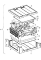
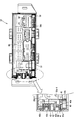
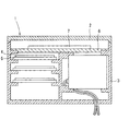
図1乃至図6は、本発明の実施形態を示し、電気接続箱10は、ロアケース11の上面側に内部回路体20を配置し、該内部回路体20の上部で且つケース中央位置にリレーモジュール30を配置し、該リレーモジュール30を囲む外周位置にヒューズモジュール40とコネクタモジュール50、51を配置し、リレーモジュール30の上方にECU(電子制御ユニット)60を配置し、さらにアッパーケース12を被せて形成している。
Embodiments of the present invention will be described with reference to the drawings.
1 to 6 show an embodiment of the present invention. In an
先ず、ECU(電子制御ユニット)60の配置構造について説明する。
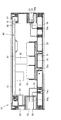
ECU60を下方から支持しているコネクタモジュール50、51は、それぞれ電気接続箱10の右側面、左側面に配置するものであり、コネクタモジュール50、51にそれぞれ設けた複数のコネクタ収容部52、53をロアケース11とアッパーケース12の間の側面位置で外部に露出させている。
また、一方のコネクタモジュール50の上面にはECU60のECUコネクタ部63を嵌合する凹部55を設けている。
First, the arrangement structure of the ECU (electronic control unit) 60 will be described.
The
Further, a
コネクタモジュール50、51のアッパーケース側端面の両側には、図1及び図2に示すように、ECU基板取付用の突起部57を設けると共に、該突起部57の近傍には固定するECU基板61の周縁に沿うリブ58を突設している。
As shown in FIGS. 1 and 2, ECU
一方、ECU60のECU基板61には、コネクタモジュール50、51の突起部57に対向する位置に取付部となる貫通孔66を穿設すると共に、コネクタモジュール50の凹部55に対向する位置にECUコネクタ部63をECU基板61の下面周縁より突設している。
よって、ECU60の貫通孔66にコネクタモジュール50、51の突起部57を貫通させると、ECUコネクタ部63がコネクタモジュール50の凹部55に嵌合され、ECUコネクタ部63とコネクタモジュール50のコネクタ収容部52が連設してケース側面位置で外部に露出される。
On the other hand, the
Therefore, when the
また、アッパーケース12の下面には所要箇所に押圧用突起15を突設しており、ECU60の上面側にアッパーケース12を被せると押圧用突起15がECU基板61をコネクタモジュール50、51側へ押圧し、ECU基板61の貫通孔66に貫通されたコネクタモジュール50、51の突起57が抜けなくなり、ECU60がコネクタモジュール50、51上に位置決め固定される。
Further, a
上記のように、ECU60がコネクタモジュール50、51上に位置決め固定された状態で、ECU基板61の下面側の導体に半田付けにより取り付けられている電子部品62がリレーモジュール30の絶縁基板31より突設している複数のリレー33間の空間部に突出している。
なお、コネクタモジュール50、51に設けた突起部57は、外周位置に設けたヒューズモジュール40に設けてもよい。
As described above, in a state where the
The
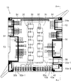
次に、内部回路体20、リレーモジュール30、ヒューズモジュール40、コネクタモジュール50、51及びECU60の接続構造について説明する。
前記内部回路体20の導体は電線wとし、該電線wを下面開口のボックス形状のケース21の下面側に配線してケース21の内部に収容している。ケース21の上壁22には、図3に示すように、リレーモジュール30、ヒューズモジュール40及びコネクタモジュール50、51の配置位置近傍に複数の端子孔23、24、25を穿設しており、該端子孔23、24、25にリレーモジュール30のバスバー32、ヒューズモジュール40、コネクタモジュール50、51の各接続用端子43、54を貫通させてケース21内部の電線wと接続している。
また、ヒューズモジュール40及びコネクタモジュール50、51を配置しない周縁より雄コネクタ部26を突設し、ECU60の雌コネクタ部65と嵌合させて電線wをECUの導体と接続している。
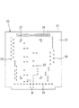
内部回路体20のケース21の上壁22の中央には、上壁22の上面に載置するリレーモジュール30の絶縁板31の4隅を位置決め固定するためのL字状の位置決め突起27を所要の4箇所に突設している。
なお、内部回路体20の下面側には、絶縁板28を配置している。
Next, the connection structure of the
The conductor of the
Further, a
At the center of the
An insulating
前記リレーモジュール30は、内部回路体20の上部かつケース中央位置に配置されるものであり、絶縁板31の上面に導電性金属板を所要形状に打ち抜いて形成したバスバー32を固定しており、該バスバー32にリレー33の端子部を溶接してリレー33を絶縁板31に固定している。
The
リレーモジュール30には図4に示す入力側バスバー32aを介して電力が供給されている。該入力側バスバー32aは一端32a−1をコネクタモジュール50の電源入力部となるコネクタ収容部56内に突出させており、電源コネクタ内の端子と接続される。入力側バスバー32aの他端にはリレー33の入力端子部を溶接により接続している。
一方、リレーモジュール30の出力側は、ヒューズモジュール40のヒューズ44と接続する出力側バスバー32bは絶縁板31から側方に突出させて、先端の圧接タブ32b−1をヒューズモジュール40のヒューズ収容部41内に突出させてヒューズ44の入力側の端子部に圧接する一方、ヒューズ44と接続しない出力側バスバー32cは絶縁板31から下方に突出させて内部回路体20のケース21に設けた端子孔23を貫通させて内部回路の電線wに圧接している。
なお、リレーモジュール30は、プリント基板上に複数のリレーを実装したものであってもよい。
Electric power is supplied to the
On the other hand, on the output side of the
Note that the
前記ヒューズモジュール40は、電気接続箱10の前側面(図3中の下側)に配置されるものであり、上下2段のヒューズ収容部41を水平方向に並設し、該ヒューズ収容部41をロアケース11とアッパーケース12の間の側面位置で外部に露出させている。上下のヒューズ収容部41はそれぞれ水平方向に位置をずらして千鳥配置としている。
The
ヒューズ収容部41に収容するヒューズ44の入力側の端子部と接続するバスバー42は、図4に示すように、一端に圧接タブ42aを設けてヒューズ44の端子部に圧接する一方、他端の接続部42bを電気接続箱10の右側面に配置するコネクタモジュール50側に突出させて、該接続部42bを前記リレーモジュール30の入力側バスバー32aから分岐した接続部32a−2に抵抗溶接により接続し、溶接部45を形成している。よって、コネクタモジュール50の電源入力部となるコネクタ収容部56に電源コネクタを嵌合すると、リレーモジュール30と共にヒューズモジュール40にも電力が供給される。また、入力側の端子を前記バスバー42に接続しないヒューズ44は、リレーモジュール30から突出させた前記出力側バスバー32bの圧接タブ32b−1に入力側の端子部を接続している。
ヒューズ44の出力側の端子部には、図5に示すように、両端に圧接部を設けたL字状の接続用端子43を接続しており、一端の圧接部43aをヒューズ収容部41内に突出させてヒューズ44の端子部に圧接する一方、他端側を下方に折り曲げて内部回路体20のケース21に設けた端子孔24に貫通させて他端の圧接部43bを電線wに圧接している。
As shown in FIG. 4, the
As shown in FIG. 5, an L-shaped
コネクタモジュール50、51は、前記のように、コネクタモジュール50、51にそれぞれ設けた複数のコネクタ収容部52、53をロアケース11とアッパーケース12の間の側面位置で外部に露出させている。また、右側面に配置するコネクタモジュール50には、電源入力部となるコネクタ収容部56を設けて、側面位置で外部に露出させている。
As described above, the
コネクタ収容部52、53に嵌合する相手方コネクタ内の端子と接続する接続用端子54は、すべてL字状とし、一端を雄タブ54aとしてコネクタ収容部52、53内に突出させて相手方コネクタ内の端子と接続する一方、他端側を下方に屈折させて延在させ、内部回路体20のケース21に設けた端子孔25に貫通させて先端の圧接部54bを内部回路の電線wに圧接している。
The
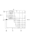
図6は、内部回路体20、リレーモジュール30、ヒューズモジュール40、コネクタモジュール50、51により形成される回路図を示す。負荷側へ電力を供給する電源回路70は電源入力部からリレーモジュール30、ヒューズモジュール40及び内部回路体20を介してコネクタモジュール50、51に接続されている。電源回路70を制御する制御回路71は、電源入力部からリレーモジュール30及び内部回路体20を介してコネクタモジュール50、51に接続されている。また、他の回路72は、リレーモジュール30のリレー33を介さずに電源入力部に溶接部45で接続し、直接ヒューズモジュール40及び内部回路体20を介してコネクタモジュール50、51に接続している。
FIG. 6 shows a circuit diagram formed by the
前記ECU60には、図1に示すように、電気接続箱10の後面側にECU基板61の下面周縁に沿って雌コネクタ部65を突設し、内部回路体20の雄コネクタ部26と嵌合させて、各コネクタ内の端子同士を接続し、内部回路の電線wとECU60の導体とを接続し、ECU60へ電力を供給している。
また、ECUコネクタ部63には、一端をECU60の導体と接続させた接続用端子64の他端を突出させており、ECUコネクタ部63に嵌合する相手方コネクタ内の端子と接続される。
As shown in FIG. 1, the
Further, the other end of the
前記ロアケース11は略四角形状の底板の4隅より連結枠13を突設し、略四角形状のアッパーケース12と連結枠13を介して連結し、ロアケース11とアッパーケース12との間の前面側にヒューズモジュール40を配置すると共に左右側面にコネクタモジュール50、51を直交配置している。また、絶縁板31上に搭載する多数のリレー33を上方から搭載するのに対して、ヒューズモジュール40のヒューズ取付方向およびコネクタモジュール50、51のコネクタ収容部に嵌合するコネクタの取付方向を側方からとして直交方向としている
前記連結枠13はL字状とし、両端に各モジュールの両側をスライドさせてガイドするガイド溝14を設けている。
The
次に、電気接続箱10の製造方法について説明する。
先ず、ロアケース11内に下方から絶縁板28と内部回路体20を収容する。
次いで、リレーモジュール30の入力側バスバー32aの一端32a−1をコネクタモジュール50のコネクタ収容部56内に突出させると共に、出力側バスバー32bの圧接タブ32b−1をヒューズモジュール40のヒューズ収容部41内に突出させ、入力側バスバー32aの接続部32a−2とヒューズモジュール40のバスバー42の接続部42bを重ねて抵抗溶接により接続する。このようにして一体となったリレーモジュール30、ヒューズモジュール40、コネクタモジュール50とコネクタモジュール51を内部回路体20の上部に配置する。このとき、各モジュールの接続用端子やバスバーの圧接タブを内部回路体20のケース21の端子孔に貫通させて内部回路を構成する電線wに圧接している。
次いで、これらモジュールの上部にECUを配置し、雌コネクタ部65を内部回路体20の雄コネクタ部26と嵌合させて、内部回路の電線wとECU60の導体とを接続している。また、ECUコネクタ部63をコネクタモジュール50の凹部55に嵌合させている。
最後に、アッパーケース12を被せ、連結枠13を介してロアケース11と連結している。
Next, a method for manufacturing the
First, the insulating
Next, one
Next, the ECU is arranged on the upper part of these modules, and the
Finally, the
前記構成とすると、ケース内に収容するECU60をケースの左右両側に設けたコネクタモジュール50、51により支持して所要の高さ位置に配置しているため、ケースに収容しているリレーモジュール30との間に所要の空間を設けて空気絶縁することができ、従来必要としていた絶縁板を不要とすることができる。これにより、部品点数を低減できると共に、電気接続箱10の薄型化及び軽量化を図ることができる。
With the above configuration, since the
また、各コネクタモジュール50、51のアッパーケース12側端面の両側に設けたECU基板取付用の突起部57をECU基板61の貫通孔66に貫通させるだけで簡単にECU60をケース内に固定することができる。
さらに、ECU基板61に取り付けられる電子部品62をリレーモジュール30の絶縁基板31より突設される複数のリレー33の間の空間部に突出させているため、リレーモジュール30の絶縁基板31とECU基板61との間隔を小さくでき、電気接続箱10を薄型化できる。
Further, the
Further, since the
特に、前記電気接続箱10を自動車の乗員の前方位置に配置する場合には、電気接続箱10を薄型化したことにより、パネルと電気接続箱10との間にスペースを設けることができるため、乗員が急ブレーキ等によりパネルに衝突したときにパネルを十分に凹ませて乗員への衝撃を低減して乗員を保護することができる。
なお、本実施形態では、コネクタモジュールによりECUを下方から支持しているが、ヒューズモジュールやリレーモジュールにより支持する構成としてもよい。
In particular, when the
In the present embodiment, the ECU is supported from below by the connector module, but may be configured to be supported by a fuse module or a relay module.
10 電気接続箱
11 ロアケース
12 アッパーケース
15 押圧用突起
20 内部回路体
30 リレーモジュール
33 リレー
40 ヒューズモジュール
50、51 コネクタモジュール
55 凹部
57 突起部
60 ECU
63 ECUコネクタ部
66 貫通孔
w 電線
DESCRIPTION OF
63
Claims (4)
ECUの基板の対向する端面にそれぞれ前記突起部と係合して固定される取付部を設け、前記ECUの基板を前記モジュールで支持して、前記ロアケースとアッパーケースの内部に配置していることを特徴とする電気接続箱。 At least one of a connector module, a fuse module, and a relay module is arranged between the lower case and the upper case facing each other so as to face the outside, and a protrusion for attaching the ECU board is provided on the upper case side end face of the module. While providing
Mounting portions that are respectively engaged with and fixed to the protrusions are provided on opposing end surfaces of the ECU board, and the ECU board is supported by the module and disposed inside the lower case and the upper case. An electrical junction box characterized by.
前記ロアケースとアッパーケースとは略四角形状とし、ロアケースの4隅より突設する連結枠を介してアッパーケースと結合し、ケース全体を薄い略四角形状としている請求項1乃至請求項3のいずれか1項に記載の電気接続箱。 An internal circuit body using a wire as a conductor is disposed in the lower case, the relay module is disposed above the internal circuit body, and the connector module and the fuse module are exposed to the outside so as to surround the periphery of the relay module. And arrange the ECU above the relay module, and arrange an upper case above the ECU,
The lower case and the upper case have a substantially rectangular shape, and are connected to the upper case via connection frames protruding from four corners of the lower case, so that the entire case has a thin, substantially rectangular shape. The electrical junction box according to item 1.
Priority Applications (5)
| Application Number | Priority Date | Filing Date | Title |
|---|---|---|---|
| JP2004109282A JP4254600B2 (en) | 2004-04-01 | 2004-04-01 | Electrical junction box |
| DE200510013513 DE102005013513A1 (en) | 2004-04-01 | 2005-03-23 | Relay for automotive electrical connector box, has terminals to which leads of lead-type resistor are connected when relay is to be connected to circuit requiring resistor |
| DE102005013514A DE102005013514A1 (en) | 2004-04-01 | 2005-03-23 | Electrical connection box |
| DE102005013511.0A DE102005013511B4 (en) | 2004-04-01 | 2005-03-23 | Electrical connection box |
| US11/092,726 US7125262B2 (en) | 2004-04-01 | 2005-03-30 | Electrical connector box |
Applications Claiming Priority (1)
| Application Number | Priority Date | Filing Date | Title |
|---|---|---|---|
| JP2004109282A JP4254600B2 (en) | 2004-04-01 | 2004-04-01 | Electrical junction box |
Publications (2)
| Publication Number | Publication Date |
|---|---|
| JP2005295724A true JP2005295724A (en) | 2005-10-20 |
| JP4254600B2 JP4254600B2 (en) | 2009-04-15 |
Family
ID=35054956
Family Applications (1)
| Application Number | Title | Priority Date | Filing Date |
|---|---|---|---|
| JP2004109282A Expired - Fee Related JP4254600B2 (en) | 2004-04-01 | 2004-04-01 | Electrical junction box |
Country Status (3)
| Country | Link |
|---|---|
| US (1) | US7125262B2 (en) |
| JP (1) | JP4254600B2 (en) |
| DE (1) | DE102005013514A1 (en) |
Cited By (10)
| Publication number | Priority date | Publication date | Assignee | Title |
|---|---|---|---|---|
| JP2007259539A (en) * | 2006-03-22 | 2007-10-04 | Sumitomo Wiring Syst Ltd | Vehicle-mounted electrical connection box |
| US7616438B2 (en) | 2006-11-21 | 2009-11-10 | Autonetworks Technologies, Ltd. | Electric connection box |
| US7616439B2 (en) | 2006-11-16 | 2009-11-10 | Autonetworks Technologies, Ltd. | Electric connection box |
| JP2011120446A (en) * | 2009-11-09 | 2011-06-16 | Autonetworks Technologies Ltd | Electric junction box |
| US8654528B2 (en) | 2006-11-16 | 2014-02-18 | Autonetworks Technologies, Ltd. | Electric connection box |
| JP2016025738A (en) * | 2014-07-18 | 2016-02-08 | 矢崎総業株式会社 | Electric connection box |
| JP2016046892A (en) * | 2014-08-21 | 2016-04-04 | 矢崎総業株式会社 | Electrical junction box |
| KR20190076357A (en) * | 2017-12-22 | 2019-07-02 | 주식회사 유라코퍼레이션 | Connector module |
| WO2022264868A1 (en) * | 2021-06-16 | 2022-12-22 | 株式会社オートネットワーク技術研究所 | Electrical connection box |
| WO2022264867A1 (en) * | 2021-06-16 | 2022-12-22 | 株式会社オートネットワーク技術研究所 | Electrical junction box |
Families Citing this family (11)
| Publication number | Priority date | Publication date | Assignee | Title |
|---|---|---|---|---|
| JP4254601B2 (en) * | 2004-04-02 | 2009-04-15 | 住友電装株式会社 | Electrical junction box |
| US7255599B1 (en) * | 2006-08-31 | 2007-08-14 | John Mezzalingua Associates, Inc. | Impedance matched waterproof connector for CATV filter housing |
| US7591653B2 (en) * | 2006-09-08 | 2009-09-22 | Aees, Inc. | Modular power distribution center |
| CN201562930U (en) * | 2009-11-26 | 2010-08-25 | 深圳长城开发科技股份有限公司 | Electronic equipment |
| DE102010025085A1 (en) * | 2010-06-25 | 2011-12-29 | Continental Automotive Gmbh | Control device e.g. electrical control device, for motor car to control e.g. vehicle functions, has circuitry carriers designed such that electrical contact is arranged between contacting unit and one of circuitry carriers |
| JP5696691B2 (en) * | 2012-06-20 | 2015-04-08 | 住友電装株式会社 | Electrical junction box |
| FR3040833B1 (en) * | 2015-09-04 | 2017-09-08 | Delphi France Sas | ELECTRICAL POWER DISTRIBUTION SYSTEM FOR VEHICLE |
| CN110212142B (en) * | 2018-12-05 | 2022-04-22 | 中航光电科技股份有限公司 | Integrated connector for battery pack and fuse box breaker module thereof |
| JP7383899B2 (en) * | 2019-03-29 | 2023-11-21 | 株式会社デンソー | rotating electric machine |
| JP7167846B2 (en) * | 2019-05-15 | 2022-11-09 | 株式会社オートネットワーク技術研究所 | electric junction box |
| US12135591B2 (en) * | 2022-07-06 | 2024-11-05 | Gm Cruise Holdings Llc | Environmental and electromagnetic seal for autonomous vehicle control systems |
Family Cites Families (6)
| Publication number | Priority date | Publication date | Assignee | Title |
|---|---|---|---|---|
| JP3336971B2 (en) | 1998-09-09 | 2002-10-21 | 住友電装株式会社 | Automotive electrical junction box |
| EP1018783B1 (en) * | 1999-01-04 | 2003-06-18 | Sumitomo Wiring Systems, Ltd. | Electrical junction box having a bus bar |
| JP2000285988A (en) | 1999-04-01 | 2000-10-13 | Yazaki Corp | Connection structure between lead and busbar |
| JP2002027634A (en) | 2000-07-03 | 2002-01-25 | Yazaki Corp | Wiring board connection structure |
| JP2002084630A (en) | 2000-09-07 | 2002-03-22 | Sumitomo Wiring Syst Ltd | Electrical junction box for high voltage |
| EP1586488A1 (en) * | 2000-10-26 | 2005-10-19 | Sumitomo Wiring Systems, Ltd. | Electrical junction box for a vehicle |
-
2004
- 2004-04-01 JP JP2004109282A patent/JP4254600B2/en not_active Expired - Fee Related
-
2005
- 2005-03-23 DE DE102005013514A patent/DE102005013514A1/en not_active Withdrawn
- 2005-03-30 US US11/092,726 patent/US7125262B2/en not_active Expired - Fee Related
Cited By (15)
| Publication number | Priority date | Publication date | Assignee | Title |
|---|---|---|---|---|
| JP2007259539A (en) * | 2006-03-22 | 2007-10-04 | Sumitomo Wiring Syst Ltd | Vehicle-mounted electrical connection box |
| US7616439B2 (en) | 2006-11-16 | 2009-11-10 | Autonetworks Technologies, Ltd. | Electric connection box |
| US8654528B2 (en) | 2006-11-16 | 2014-02-18 | Autonetworks Technologies, Ltd. | Electric connection box |
| US7616438B2 (en) | 2006-11-21 | 2009-11-10 | Autonetworks Technologies, Ltd. | Electric connection box |
| JP2011120446A (en) * | 2009-11-09 | 2011-06-16 | Autonetworks Technologies Ltd | Electric junction box |
| JP2016025738A (en) * | 2014-07-18 | 2016-02-08 | 矢崎総業株式会社 | Electric connection box |
| JP2016046892A (en) * | 2014-08-21 | 2016-04-04 | 矢崎総業株式会社 | Electrical junction box |
| KR20190076357A (en) * | 2017-12-22 | 2019-07-02 | 주식회사 유라코퍼레이션 | Connector module |
| KR101996460B1 (en) * | 2017-12-22 | 2019-07-04 | 주식회사 유라코퍼레이션 | Connector module |
| WO2022264868A1 (en) * | 2021-06-16 | 2022-12-22 | 株式会社オートネットワーク技術研究所 | Electrical connection box |
| WO2022264867A1 (en) * | 2021-06-16 | 2022-12-22 | 株式会社オートネットワーク技術研究所 | Electrical junction box |
| JP7558493B2 (en) | 2021-06-16 | 2024-10-01 | 株式会社オートネットワーク技術研究所 | Electrical Junction Box |
| JP7558492B2 (en) | 2021-06-16 | 2024-10-01 | 株式会社オートネットワーク技術研究所 | Electrical Junction Box |
| US12431694B2 (en) | 2021-06-16 | 2025-09-30 | Autonetworks Technologies, Ltd. | Electrical junction box |
| US12477665B2 (en) | 2021-06-16 | 2025-11-18 | Autonetworks Technologies, Ltd. | Electrical junction box |
Also Published As
| Publication number | Publication date |
|---|---|
| DE102005013514A1 (en) | 2005-10-27 |
| JP4254600B2 (en) | 2009-04-15 |
| US7125262B2 (en) | 2006-10-24 |
| US20050221641A1 (en) | 2005-10-06 |
Similar Documents
| Publication | Publication Date | Title |
|---|---|---|
| JP4254600B2 (en) | Electrical junction box | |
| JP4254601B2 (en) | Electrical junction box | |
| JP2000092661A (en) | Electrical junction box | |
| JP4238797B2 (en) | Electrical junction box | |
| JP2006187050A (en) | Junction block | |
| US20210287843A1 (en) | Coil assembly, circuit assembly, and electrical junction box | |
| JP2013123342A (en) | Electric connection box | |
| JP4424042B2 (en) | Automotive relays and electrical junction boxes | |
| JP2012120318A (en) | Electric connection box | |
| JP2000092659A (en) | Electrical junction box | |
| JP2011120431A (en) | Electrical junction box | |
| JPH11191914A (en) | Electrical junction box | |
| JP5376209B2 (en) | Circuit structure | |
| JP2007005142A (en) | Connector and electrical junction box provided with the connector | |
| JP4800079B2 (en) | Electrical junction box | |
| JP2012134086A (en) | Electric connection box | |
| JP4728873B2 (en) | Wiring board unit | |
| JP5531565B2 (en) | Electrical junction box and method of manufacturing electrical junction box | |
| JP2007151296A (en) | Board with connector | |
| JP2007311152A (en) | Wiring board unit | |
| JP2025156766A (en) | Conductor holding structure and electrical connection box | |
| JP3747777B2 (en) | Junction box | |
| JP2001309526A (en) | Connecting structure for internal circuit of junction box to relay | |
| JP2005354876A (en) | Electrical junction box | |
| JPH0850946A (en) | Busbar connection device for electrical junction box |
Legal Events
| Date | Code | Title | Description |
|---|---|---|---|
| A621 | Written request for application examination |
Free format text: JAPANESE INTERMEDIATE CODE: A621 Effective date: 20060616 |
|
| A977 | Report on retrieval |
Free format text: JAPANESE INTERMEDIATE CODE: A971007 Effective date: 20080325 |
|
| A131 | Notification of reasons for refusal |
Free format text: JAPANESE INTERMEDIATE CODE: A131 Effective date: 20080527 |
|
| A521 | Request for written amendment filed |
Free format text: JAPANESE INTERMEDIATE CODE: A523 Effective date: 20080728 |
|
| A131 | Notification of reasons for refusal |
Free format text: JAPANESE INTERMEDIATE CODE: A131 Effective date: 20080902 |
|
| A521 | Request for written amendment filed |
Free format text: JAPANESE INTERMEDIATE CODE: A523 Effective date: 20081104 |
|
| TRDD | Decision of grant or rejection written | ||
| A01 | Written decision to grant a patent or to grant a registration (utility model) |
Free format text: JAPANESE INTERMEDIATE CODE: A01 Effective date: 20090106 |
|
| A01 | Written decision to grant a patent or to grant a registration (utility model) |
Free format text: JAPANESE INTERMEDIATE CODE: A01 |
|
| A61 | First payment of annual fees (during grant procedure) |
Free format text: JAPANESE INTERMEDIATE CODE: A61 Effective date: 20090119 |
|
| FPAY | Renewal fee payment (event date is renewal date of database) |
Free format text: PAYMENT UNTIL: 20120206 Year of fee payment: 3 |
|
| R150 | Certificate of patent or registration of utility model |
Free format text: JAPANESE INTERMEDIATE CODE: R150 |
|
| FPAY | Renewal fee payment (event date is renewal date of database) |
Free format text: PAYMENT UNTIL: 20130206 Year of fee payment: 4 |
|
| FPAY | Renewal fee payment (event date is renewal date of database) |
Free format text: PAYMENT UNTIL: 20140206 Year of fee payment: 5 |
|
| LAPS | Cancellation because of no payment of annual fees |