JP2005295711A - Hybrid electric automobile - Google Patents
Hybrid electric automobile Download PDFInfo
- Publication number
- JP2005295711A JP2005295711A JP2004108477A JP2004108477A JP2005295711A JP 2005295711 A JP2005295711 A JP 2005295711A JP 2004108477 A JP2004108477 A JP 2004108477A JP 2004108477 A JP2004108477 A JP 2004108477A JP 2005295711 A JP2005295711 A JP 2005295711A
- Authority
- JP
- Japan
- Prior art keywords
- energy storage
- hybrid electric
- energy
- electric vehicle
- turbine
- Prior art date
- Legal status (The legal status is an assumption and is not a legal conclusion. Google has not performed a legal analysis and makes no representation as to the accuracy of the status listed.)
- Pending
Links
- 238000004146 energy storage Methods 0.000 claims abstract description 16
- 238000002485 combustion reaction Methods 0.000 claims abstract description 15
- 239000000446 fuel Substances 0.000 claims description 17
- 239000003990 capacitor Substances 0.000 claims description 8
- 230000001172 regenerating effect Effects 0.000 claims description 3
- HBBGRARXTFLTSG-UHFFFAOYSA-N Lithium ion Chemical compound [Li+] HBBGRARXTFLTSG-UHFFFAOYSA-N 0.000 claims description 2
- 229910001416 lithium ion Inorganic materials 0.000 claims description 2
- 229910052987 metal hydride Inorganic materials 0.000 claims description 2
- 229910052759 nickel Inorganic materials 0.000 claims description 2
- PXHVJJICTQNCMI-UHFFFAOYSA-N nickel Substances [Ni] PXHVJJICTQNCMI-UHFFFAOYSA-N 0.000 claims description 2
- -1 nickel metal hydride Chemical class 0.000 claims description 2
- 230000005855 radiation Effects 0.000 claims 1
- 238000005265 energy consumption Methods 0.000 abstract 1
- 238000010248 power generation Methods 0.000 description 5
- 230000005540 biological transmission Effects 0.000 description 3
- 238000010792 warming Methods 0.000 description 3
- 238000010586 diagram Methods 0.000 description 2
- 230000007613 environmental effect Effects 0.000 description 2
- 239000005357 flat glass Substances 0.000 description 2
- 239000002803 fossil fuel Substances 0.000 description 2
- 239000007789 gas Substances 0.000 description 2
- 230000007246 mechanism Effects 0.000 description 2
- 230000008929 regeneration Effects 0.000 description 2
- 238000011069 regeneration method Methods 0.000 description 2
- 238000003915 air pollution Methods 0.000 description 1
- 230000002238 attenuated effect Effects 0.000 description 1
- 238000006243 chemical reaction Methods 0.000 description 1
- 230000005611 electricity Effects 0.000 description 1
- RLQJEEJISHYWON-UHFFFAOYSA-N flonicamid Chemical compound FC(F)(F)C1=CC=NC=C1C(=O)NCC#N RLQJEEJISHYWON-UHFFFAOYSA-N 0.000 description 1
- 239000012530 fluid Substances 0.000 description 1
- 210000003660 reticulum Anatomy 0.000 description 1
Images

Classifications
-
- Y—GENERAL TAGGING OF NEW TECHNOLOGICAL DEVELOPMENTS; GENERAL TAGGING OF CROSS-SECTIONAL TECHNOLOGIES SPANNING OVER SEVERAL SECTIONS OF THE IPC; TECHNICAL SUBJECTS COVERED BY FORMER USPC CROSS-REFERENCE ART COLLECTIONS [XRACs] AND DIGESTS
- Y02—TECHNOLOGIES OR APPLICATIONS FOR MITIGATION OR ADAPTATION AGAINST CLIMATE CHANGE
- Y02T—CLIMATE CHANGE MITIGATION TECHNOLOGIES RELATED TO TRANSPORTATION
- Y02T10/00—Road transport of goods or passengers
- Y02T10/60—Other road transportation technologies with climate change mitigation effect
- Y02T10/62—Hybrid vehicles
-
- Y—GENERAL TAGGING OF NEW TECHNOLOGICAL DEVELOPMENTS; GENERAL TAGGING OF CROSS-SECTIONAL TECHNOLOGIES SPANNING OVER SEVERAL SECTIONS OF THE IPC; TECHNICAL SUBJECTS COVERED BY FORMER USPC CROSS-REFERENCE ART COLLECTIONS [XRACs] AND DIGESTS
- Y02—TECHNOLOGIES OR APPLICATIONS FOR MITIGATION OR ADAPTATION AGAINST CLIMATE CHANGE
- Y02T—CLIMATE CHANGE MITIGATION TECHNOLOGIES RELATED TO TRANSPORTATION
- Y02T10/00—Road transport of goods or passengers
- Y02T10/60—Other road transportation technologies with climate change mitigation effect
- Y02T10/70—Energy storage systems for electromobility, e.g. batteries
-
- Y—GENERAL TAGGING OF NEW TECHNOLOGICAL DEVELOPMENTS; GENERAL TAGGING OF CROSS-SECTIONAL TECHNOLOGIES SPANNING OVER SEVERAL SECTIONS OF THE IPC; TECHNICAL SUBJECTS COVERED BY FORMER USPC CROSS-REFERENCE ART COLLECTIONS [XRACs] AND DIGESTS
- Y02—TECHNOLOGIES OR APPLICATIONS FOR MITIGATION OR ADAPTATION AGAINST CLIMATE CHANGE
- Y02T—CLIMATE CHANGE MITIGATION TECHNOLOGIES RELATED TO TRANSPORTATION
- Y02T10/00—Road transport of goods or passengers
- Y02T10/60—Other road transportation technologies with climate change mitigation effect
- Y02T10/7072—Electromobility specific charging systems or methods for batteries, ultracapacitors, supercapacitors or double-layer capacitors
Landscapes
- Hybrid Electric Vehicles (AREA)
- Electric Propulsion And Braking For Vehicles (AREA)
Abstract
Description
この発明は、ハイブリッド電気自動車に関する。 The present invention relates to a hybrid electric vehicle.
近年、地球温暖化や都市温暖化(ヒートアイランド)などの多様な環境問題が顕在化し、自動車の高効率化(低燃費化)、排気ガスの清浄化がなされてきたが、化石燃料を燃料とした内燃機関のみを駆動源とする自動車には改善の限界が生じ、最近では内燃機関と電気モーターを搭載したハイブリッド自動車が実用化されている。省エネルギーかつクリーンなハイブリッド電気自動車の普及は、環境問題の軽減に非常に有効である。
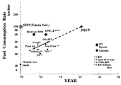
たとえば、図4は1990年から今日までの我が国における普通乗用車およびハイブリッド車の燃費を示したものである。1990年当時の10モード燃費の平均値は約12km/リットルであったが、1997年ハイブリッド車が初めて実用化され燃費が飛躍的に伸びている。最近のハイブリッド車では10・15モードで35.5km/リットルを記録している。将来、世界の自動車の台数が30億台になると推定されているが、地球環境および化石燃料資源の有効利用の観点から、車の燃費は最低でも100km/リットルを達成する必要がある。なお、図4中のSEEVは東北大の提案した高効率ハイブリッド電気自動車である(非特許文献1および2参照)。
In recent years, various environmental problems such as global warming and urban warming (heat island) have become apparent, and automobiles have been made more efficient (lower fuel consumption) and exhaust gases have been cleaned, but fossil fuels have been used as fuel. There is a limit of improvement in automobiles that use only an internal combustion engine as a drive source, and recently, hybrid cars equipped with an internal combustion engine and an electric motor have been put into practical use. The spread of energy-saving and clean hybrid electric vehicles is very effective in reducing environmental problems.
For example, FIG. 4 shows the fuel consumption of ordinary passenger cars and hybrid cars in Japan from 1990 to the present day. The average value of 10-mode fuel consumption at the time of 1990 was about 12km / liter, but in 1997, hybrid vehicles were put into practical use for the first time, and fuel consumption increased dramatically. Recent hybrid vehicles record 35.5km / liter in 10.15 mode. In the future, it is estimated that the number of automobiles in the world will be 3 billion, but from the viewpoint of effective use of the global environment and fossil fuel resources, it is necessary to achieve a minimum fuel consumption of 100 km / liter. 4 is a high-efficiency hybrid electric vehicle proposed by Tohoku University (see Non-Patent
しかしながら、これまでに実用化されたハイブリッド電気自動車は、低速走行時の電気モーターによるアシストはあるものの、依然として内燃機関による走行がベースとなっており、部分負荷による走行が多く、常にその機関の最高効率の状態で走行しているわけではない。また、エネルギー貯蔵装置の容量が小さく、長い下り坂などの回生エネルギーを十分に貯蔵することが極めて困難となっている。さらに将来の重要なエネルギー源である太陽エネルギーなどの再生可能エネルギーをほとんど利用していないのが現状である。 However, although hybrid electric vehicles put to practical use so far are assisted by electric motors at low speeds, they are still based on internal combustion engines and are often driven by partial loads. You are not driving in an efficient state. Moreover, the capacity of the energy storage device is small, and it is extremely difficult to sufficiently store regenerative energy such as a long downhill. Furthermore, the present situation is that almost no renewable energy such as solar energy, which is an important future energy source, is used.
本発明では、ハイブリッド電気自動車の大幅な高効率化を課題とする。 An object of the present invention is to greatly improve the efficiency of a hybrid electric vehicle.
以上の課題を解決するために、請求項1記載の発明では、従来の2次電池に加えて、フライホイール(Flywheel)およびキャパシタ(Capacitor)の3系統のエネルギー貯蔵装置を搭載し、常に最高効率状態で稼働する発電機からの電力をこれら3系統の装置に貯蔵し、状況に応じて最適に走行モーターを稼働する
In order to solve the above problems, in the invention described in
また、請求項2の発明では、請求項1記載のハイブリッド電気自動車において、太陽電池を搭載し、太陽光発電を適宜行うことによって、さらなる高効率化が可能となる。さらに、請求項3の発明は、深夜電力を利用することによって、内燃機関の発電効率よりも高効率な大型発電所からの安価な電力をエネルギー貯蔵装置に貯え、燃料の保有熱量をベースとした燃料消費率をさらに向上することができる。
According to the invention of
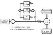
この発明の一実施形態を図1に示す。
図1はハイブリッド電気自動車のエネルギーフローを示すもので、本発明において主要な構成要素のみを概略しており、さまざまな一般の自動車を構成する多様な補機類、変速機構などは省略してある。
One embodiment of the present invention is shown in FIG.
FIG. 1 shows the energy flow of a hybrid electric vehicle. In the present invention, only main components are outlined, and various auxiliary machines, transmission mechanisms and the like constituting various general vehicles are omitted. .
オンボードチャージャー(内燃機関)1は発電機2に連結されており、通常は最高効率状態で定格稼働する。通常走行時においては矢印10に示すように、内燃機関が発電した電力は、コントローラ6によって、2次電池3、フライホイール4およびキャパシタ5に最適に振り分けられる。これら3系統のエネルギー貯蔵装置の貯蔵量が走行に必要十分に達した場合、内燃機関2は停止する。3系統の貯蔵装置のうち、コントローラ6によって走行状態に最も適した貯蔵装置から走行用のモーター7に出力され、変速機等を経由してタイヤ8に伝達される。また、下り坂や制動時の回生時においては矢印9に示すように、走行用モーターから回生電力がコントローラ6を介して3系統のエネルギー貯蔵システムに振り分けられる。2次電池、フライホイールおよびキャパシタは、それぞれエネルギー密度、入出力パワー密度が異なり、走行の負荷変動周期にあわせて最適なものを稼働する。
An on-board charger (internal combustion engine) 1 is connected to a
2次電池の例としてはリチウムイオン電池、ニッケル水素電池などが挙げられ、キャパシタの例としては電気二重層キャパシタが挙げられる。フライホイールについては、通常の雰囲気下においては、空気抵抗による貯蔵量の減衰が生じるが、場合によっては真空化により回避できる。また、同じ目的で電磁軸受を用いることがある。フライホイールエネルギー貯蔵装置は通常、モーター兼発電機が一体化しており、入出力はこれを介して電気的に行われる。しかし、場合によっては、モーター兼発電機を介さず回転エネルギーのままクラッチや変速機構を介して駆動力に直接利用する形態もとりうる。なお、オンボードチャージャー(内燃機関)1は燃料電池やガスタービンなどに置き換えられる場合もある。
また、オンボードチャージャー1として、”重ね合わせの概念”に基づくシンラタービン(SHINLA TURBINE)(非特許文献3参照)を適用する場合がある。シンラタービンは比較的単純なディスク状のディスクを軸方向に稠密に多数重ね合わせた構造を有するタービンで、作動流体から粘性・衝動・反動を複合して高効率に動力を取り出すことのできるタービン機関である。効率は60%を超え、静粛で振動も少なく、多種の燃料に対応できるという特長を有する。
Examples of the secondary battery include a lithium ion battery and a nickel metal hydride battery, and examples of the capacitor include an electric double layer capacitor. As for the flywheel, the storage amount is attenuated by air resistance in a normal atmosphere, but in some cases, it can be avoided by evacuation. Moreover, an electromagnetic bearing may be used for the same purpose. A flywheel energy storage device is usually integrated with a motor / generator, and input / output is performed electrically via the motor / generator. However, depending on the case, a form in which the rotational energy is directly used for the driving force via the clutch or the transmission mechanism without using the motor / generator can be taken. The on-board charger (internal combustion engine) 1 may be replaced with a fuel cell or a gas turbine.
In some cases, a SHINLA TURBINE (see Non-Patent Document 3) based on the “superposition concept” may be applied as the on-
図2は実施例1のエネルギーフロー図である。
他の実施例1として、前述の実施形態に加えて、太陽電池(Photovoltaic cell:PVセル)を車両に設置する例がある。太陽電池はボンネット、屋根、トランクなどの比較的平坦で太陽光が入射しやすい面に最大限に設置する。通常の普通乗用車では2平方メートル以上の設置が可能である。また、場合によっては後席窓ガラスや後部窓ガラスにシースルータイプの太陽電池を設置する場合もある。太陽電池は近い将来、発電効率が20%に達する可能性があり、エネルギー源として十分に期待できる。年間10,000km走行するとして、その30〜40%をPVセルで賄うことが可能である。図2に示すように太陽電池から得られる電力もコントローラ6を介して3系統のエネルギー貯蔵装置に適宜貯蔵される。また、例として、3系統のエネルギー貯蔵装置を介さずに太陽電池による発電で直接モーターを駆動する場合もある。
FIG. 2 is an energy flow diagram of the first embodiment.
As another example 1, in addition to the above-described embodiment, there is an example in which a solar cell (photovoltaic cell: PV cell) is installed in a vehicle. Solar cells should be installed as much as possible on bonnets, roofs, trunks and other relatively flat surfaces where sunlight can enter. Ordinary passenger cars can be installed over 2 square meters. In some cases, a see-through solar cell may be installed on the rear seat window glass or the rear window glass. In the near future, the power generation efficiency of solar cells may reach 20%, and can be expected sufficiently as an energy source. It is possible to cover 30 to 40% of the PV cell with 10,000 km per year. As shown in FIG. 2, the electric power obtained from the solar cell is also appropriately stored in the three energy storage devices via the
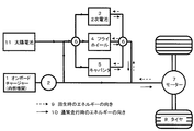
図3は実施例2のエネルギーフロー図である。
他の実施例2として、前述の実施形態ならびに実施例1に加えて、深夜電力12を利用する例がある。駐車場などに夜間駐車している時、深夜電力12を3系統のエネルギー貯蔵装置に充電・充勢することにより、走りはじめからかなりの距離(50〜100km程度)は内燃機関1による発電を行わずに走行することが可能となる。深夜電力は大型発電所によって発電されるため、一般的には内燃機関1よりも発電効率が高く、また価格も安いため、燃料の燃焼熱をベースとした効率は向上し、走行コストは低くなる。
FIG. 3 is an energy flow diagram of the second embodiment.
As another example 2, in addition to the above-described embodiment and example 1, there is an example in which the midnight power 12 is used. When parking at night in a parking lot or the like, the
以上説明したように、本発明のハイブリッド電気自動車は、3系統の大容量のエネルギー貯蔵装置と最高効率状態での稼働を行う内燃機関を組み合わせることにより効率が高められ、さらに、太陽電池および深夜電力を利用することによって、低燃費かつ低走行コストを実現できるため、産業上の利用可能性が極めて高い。10・15モードに基づく試算によるとガソリンを基準とした場合、燃費100km/リットル〜170km/リットルを達成できる可能性がある。 As described above, the hybrid electric vehicle of the present invention is improved in efficiency by combining three large-capacity energy storage devices and an internal combustion engine that operates in a maximum efficiency state, and further includes a solar cell and midnight power. By using, it is possible to realize low fuel consumption and low driving cost, so that the industrial applicability is extremely high. According to a trial calculation based on the 10.15 mode, there is a possibility that a fuel consumption of 100 km / liter to 170 km / liter can be achieved when using gasoline as a reference.
1 内燃機関
2 発電機
3 2次電池
4 フライホイール
5 キャパシタ
6 コントローラ
7 モーター
8 タイヤ
9 回生時のエネルギーの向き
10 通常走行時のエネルギーの向き
11 太陽電池
12 深夜電力
DESCRIPTION OF
Claims (4)
Priority Applications (1)
| Application Number | Priority Date | Filing Date | Title |
|---|---|---|---|
| JP2004108477A JP2005295711A (en) | 2004-03-31 | 2004-03-31 | Hybrid electric automobile |
Applications Claiming Priority (1)
| Application Number | Priority Date | Filing Date | Title |
|---|---|---|---|
| JP2004108477A JP2005295711A (en) | 2004-03-31 | 2004-03-31 | Hybrid electric automobile |
Publications (1)
| Publication Number | Publication Date |
|---|---|
| JP2005295711A true JP2005295711A (en) | 2005-10-20 |
Family
ID=35328033
Family Applications (1)
| Application Number | Title | Priority Date | Filing Date |
|---|---|---|---|
| JP2004108477A Pending JP2005295711A (en) | 2004-03-31 | 2004-03-31 | Hybrid electric automobile |
Country Status (1)
| Country | Link |
|---|---|
| JP (1) | JP2005295711A (en) |
Cited By (13)
| Publication number | Priority date | Publication date | Assignee | Title |
|---|---|---|---|---|
| GB2470478A (en) * | 2009-05-18 | 2010-11-24 | Liberty Electric Cars Ltd | Electromechanical hybrid propulsion system for road vehicles |
| CN102843095A (en) * | 2011-06-24 | 2012-12-26 | 发那科株式会社 | Motor drive apparatus equipped with energy storage unit |
| JP2013216318A (en) * | 2007-02-09 | 2013-10-24 | A123 Systems Inc | Control system with reconfigurable multi-function power converter and hybrid vehicle |
| US8808096B2 (en) | 2009-03-27 | 2014-08-19 | Ricardo Uk Limited | Flywheel |
| JP2014155292A (en) * | 2013-02-07 | 2014-08-25 | Nabtesco Corp | Power regeneration system and vehicle including the same |
| WO2015029260A1 (en) * | 2013-08-26 | 2015-03-05 | Tasaki Katsuto | Business model for establishing large-scale social power supply infrastructure system using power-generating vehicle |
| US9132737B2 (en) | 2009-12-24 | 2015-09-15 | Toyota Jidosha Kabushiki Kaisha | Electromotive force device |
| US9273755B2 (en) | 2009-03-27 | 2016-03-01 | Ricardo Uk Limited | Method and apparatus for balancing a flywheel |
| US9391489B2 (en) | 2010-11-17 | 2016-07-12 | Ricardo Uk Limited | Magnetic coupler having magnets with different magnetic strengths |
| US9704631B2 (en) | 2009-03-27 | 2017-07-11 | Ricardo Uk Limited | Flywheel |
| US9718343B2 (en) | 2011-04-20 | 2017-08-01 | Ricardo Uk Limited | Energy storage system having a flywheel for a vehicle transmission |
| WO2018184351A1 (en) * | 2017-04-06 | 2018-10-11 | 东汉新能源汽车技术有限公司 | Hybrid energy supply system and method for vehicle and hybrid energy vehicle |
| CN120348139A (en) * | 2025-06-23 | 2025-07-22 | 厦门理工学院 | Photovoltaic-double-motor hybrid power system and hybrid power vehicle |
-
2004
- 2004-03-31 JP JP2004108477A patent/JP2005295711A/en active Pending
Cited By (19)
| Publication number | Priority date | Publication date | Assignee | Title |
|---|---|---|---|---|
| JP2013216318A (en) * | 2007-02-09 | 2013-10-24 | A123 Systems Inc | Control system with reconfigurable multi-function power converter and hybrid vehicle |
| US9704631B2 (en) | 2009-03-27 | 2017-07-11 | Ricardo Uk Limited | Flywheel |
| US8808096B2 (en) | 2009-03-27 | 2014-08-19 | Ricardo Uk Limited | Flywheel |
| US9273755B2 (en) | 2009-03-27 | 2016-03-01 | Ricardo Uk Limited | Method and apparatus for balancing a flywheel |
| GB2470478A (en) * | 2009-05-18 | 2010-11-24 | Liberty Electric Cars Ltd | Electromechanical hybrid propulsion system for road vehicles |
| US9132737B2 (en) | 2009-12-24 | 2015-09-15 | Toyota Jidosha Kabushiki Kaisha | Electromotive force device |
| US9391489B2 (en) | 2010-11-17 | 2016-07-12 | Ricardo Uk Limited | Magnetic coupler having magnets with different magnetic strengths |
| US9718343B2 (en) | 2011-04-20 | 2017-08-01 | Ricardo Uk Limited | Energy storage system having a flywheel for a vehicle transmission |
| CN102843095B (en) * | 2011-06-24 | 2015-07-08 | 发那科株式会社 | Motor drive apparatus equipped with energy storage unit |
| US8901866B2 (en) | 2011-06-24 | 2014-12-02 | Fanuc Corporation | Motor drive apparatus equipped with energy storage unit |
| JP2013009524A (en) * | 2011-06-24 | 2013-01-10 | Fanuc Ltd | Motor driving device having energy storage part |
| CN102843095A (en) * | 2011-06-24 | 2012-12-26 | 发那科株式会社 | Motor drive apparatus equipped with energy storage unit |
| DE102012011914B4 (en) | 2011-06-24 | 2023-02-02 | Fanuc Corporation | Motor drive device equipped with an energy storage unit |
| JP2014155292A (en) * | 2013-02-07 | 2014-08-25 | Nabtesco Corp | Power regeneration system and vehicle including the same |
| WO2015029260A1 (en) * | 2013-08-26 | 2015-03-05 | Tasaki Katsuto | Business model for establishing large-scale social power supply infrastructure system using power-generating vehicle |
| JPWO2015029260A1 (en) * | 2013-08-26 | 2017-03-02 | 勝人 田崎 | Business model for constructing large-scale power supply infrastructure systems using power generation vehicles |
| WO2018184351A1 (en) * | 2017-04-06 | 2018-10-11 | 东汉新能源汽车技术有限公司 | Hybrid energy supply system and method for vehicle and hybrid energy vehicle |
| JP2019512993A (en) * | 2017-04-06 | 2019-05-16 | 東漢新能源汽車技術有限公司Dong Han New Energy Automotive Technology Co.,Ltd | Combined energy supply system and method for vehicle, combined energy vehicle |
| CN120348139A (en) * | 2025-06-23 | 2025-07-22 | 厦门理工学院 | Photovoltaic-double-motor hybrid power system and hybrid power vehicle |
Similar Documents
| Publication | Publication Date | Title |
|---|---|---|
| Åhman | Primary energy efficiency of alternative powertrains in vehicles | |
| Tie et al. | A review of energy sources and energy management system in electric vehicles | |
| US8509973B2 (en) | High performance and improved efficiency electric vehicle and methods of production | |
| JP2005295711A (en) | Hybrid electric automobile | |
| CN102653241A (en) | Photovoltaic and wind power generation hybrid electric vehicle | |
| Ren et al. | Review of energy storage technologies for extended range electric vehicle | |
| Jha et al. | A review on hybrid electric vehicles and power sources | |
| CN101254755A (en) | Novel environment-protection self-assist multi-power multi-drive solar car | |
| CN201033533Y (en) | solar hybrid car | |
| CN202911568U (en) | Photovoltaic wind power generation type hybrid car | |
| AU2021102602A4 (en) | IOT based device for social distancing to stop spreading coronavirus | |
| CN101746277A (en) | Wind-light electric vehicle | |
| Goel et al. | Solar hybrid electric vehicle—A green vehicle for future impulse | |
| CN202271859U (en) | Environment-friendly electric motor car | |
| CN203246316U (en) | Magnetism-stress coupled series-structured hybrid power system of automobile | |
| Dinakaran et al. | Performance evaluation on electric vehicle by solar photovoltaic system | |
| JP2020124049A (en) | Electric vehicles | |
| Chau | Electric vehicles | |
| CN202806343U (en) | Multi-energy source vehicle | |
| Gaddy | Photovoltaics for hybrid automobiles | |
| Rajeev | Methods to Reduce Dependency on Conventional Battery in Electric Vehicles | |
| CN102874090A (en) | Multi-power vehicle | |
| CN103231646A (en) | Magnetism-stress coupling parallel-shaft parallel structure automobile hybrid power system and method | |
| JPH03270603A (en) | Electric car | |
| Ueda et al. | Challenges of Widespread Marketplace Acceptance of Electric Vehicles--Towards a Zero-Emission Mobility Society |