JP2005295523A - Transmitting apparatus and wireless communication apparatus - Google Patents
Transmitting apparatus and wireless communication apparatus Download PDFInfo
- Publication number
- JP2005295523A JP2005295523A JP2005064655A JP2005064655A JP2005295523A JP 2005295523 A JP2005295523 A JP 2005295523A JP 2005064655 A JP2005064655 A JP 2005064655A JP 2005064655 A JP2005064655 A JP 2005064655A JP 2005295523 A JP2005295523 A JP 2005295523A
- Authority
- JP
- Japan
- Prior art keywords
- correction
- amplifier
- transmission
- frequency power
- signal
- Prior art date
- Legal status (The legal status is an assumption and is not a legal conclusion. Google has not performed a legal analysis and makes no representation as to the accuracy of the status listed.)
- Granted
Links
Images


Classifications
-
- Y02B60/50—
Landscapes
- Transmitters (AREA)
- Mobile Radio Communication Systems (AREA)
Abstract
【課題】 電力効率が良好で、送信出力電力の制御範囲が広く、かつ安定した電力を出力することができる送信装置及び無線通信装置を提供する。
【解決手段】 送信装置100は、第1のモードにおいて高周波電力増幅器105を非線形増幅器として動作させ、第2のモードにおいて高周波電力増幅器105を線形増幅器として動作させる。非線形増幅器として動作させる場合、高周波電力増幅器105の入力レベルは可変利得増幅器107により送信信号の平均出力電力に応じて変化する。更に、送信装置100は、高周波電力増幅器105の各モードの切換動作において誤差を減少するための補正テーブル121を備える。
【選択図】 図1
PROBLEM TO BE SOLVED: To provide a transmission device and a wireless communication device that have good power efficiency, have a wide control range of transmission output power, and can output stable power.
A transmission apparatus 100 operates a high frequency power amplifier 105 as a nonlinear amplifier in a first mode, and operates the high frequency power amplifier 105 as a linear amplifier in a second mode. When operating as a nonlinear amplifier, the input level of the high-frequency power amplifier 105 is changed by the variable gain amplifier 107 in accordance with the average output power of the transmission signal. Furthermore, the transmission device 100 includes a correction table 121 for reducing errors in the switching operation of each mode of the high-frequency power amplifier 105.
[Selection] Figure 1
Description
本発明は、送信装置及び無線通信装置に関し、特に送信信号を電力増幅して出力する送信装置及び無線通信装置に関する。 The present invention relates to a transmission apparatus and a wireless communication apparatus, and more particularly to a transmission apparatus and a wireless communication apparatus that amplify a transmission signal and output the signal.
従来、包絡線変動成分を含む変調信号を増幅する高周波電力増幅器には、包絡線変動成分を線形に増幅するためにA級又はAB級の線形増幅器が用いられてきた。このような線形増幅器は、線形性には優れている反面、常時直流バイアス成分に伴う電力を消費しているために、C級乃至E級等の非線形増幅器に比べて電力効率が低い。このため、このような高周波電力増幅器を、電池を電源とする携帯型の無線機に適用した場合、高周波電力増幅器の電力消費量が多いため使用時間が短くなってしまう事情があった。また、大電力の送信装置を複数設置する無線システムの基地局装置に適用した場合においては、装置の大型化や発熱量の増大を招いてしまう事情があった。 Conventionally, class A or class AB linear amplifiers have been used for high frequency power amplifiers that amplify modulated signals including envelope fluctuation components in order to linearly amplify envelope fluctuation components. Such a linear amplifier is excellent in linearity, but consumes electric power associated with a DC bias component at all times, and therefore has lower power efficiency than a non-linear amplifier of class C to class E. For this reason, when such a high-frequency power amplifier is applied to a portable radio device using a battery as a power source, there is a situation in which the use time is shortened because the power consumption of the high-frequency power amplifier is large. In addition, when applied to a base station apparatus of a wireless system in which a plurality of high-power transmission apparatuses are installed, there are circumstances in which the apparatus becomes large and the amount of heat generation increases.
そこで、高効率の送信装置として、図14に示すポーラ変調方式を採用した送信装置1が提案されている。この送信装置1は、振幅位相分離部2と、振幅変調信号増幅器3と、周波数シンセサイザ4と、非線形型増幅器である高周波電力増幅器5と、を備えている。
Therefore, as a highly efficient transmission apparatus, a
振幅位相分離部2にはベースバンド変調信号20が入力される。振幅位相分離部2から出力されたベースバンド振幅変調信号21は振幅変調信号増幅器3に入力される。振幅位相分離部2から出力されたベースバンド位相変調信号23は周波数シンセサイザ4に入力される。周波数シンセサイザ4から出力された高周波位相変調信号24は高周波電力増幅器5に入力される。高周波電力増幅器5においては送信出力信号25が出力される。
A
次に、送信装置1の動作を説明する。まず、ベースバンド変調信号20をSi(t)とすると、このベースバンド変調信号Si(t)は次式1で表すことができる。
Next, the operation of the
Si(t)=a(t)exp[jφ(t)] …(1)
ここで、a(t)は振幅データであり、exp[jφ(t)]は位相データである。振幅位相分離部2によりベースバンド変調信号Si(t)から振幅データa(t)と位相データexp[jφ(t)]とが抽出される。振幅データa(t)はベースバンド振幅変調信号21に、位相データexp[jφ(t)]はベースバンド位相変調信号22に、それぞれ対応する。振幅データa(t)は振幅変調信号増幅器3で増幅されて高周波電力増幅器5に与えられる。これにより、高周波電力増幅器5の電源電圧値が振幅データa(t)に基づいて設定される。
Si (t) = a (t) exp [jφ (t)] (1)
Here, a (t) is amplitude data, and exp [jφ (t)] is phase data. The amplitude
周波数シンセサイザ4は搬送波角周波数ωcを位相データexp[jφ(t)]で変調した高周波位相変調信号24を生成し、この高周波位相変調信号24が高周波電力増幅器5に入力される。ここで、高周波位相変調信号24をScとすると、この高周波位相変調信号Scは次式2で表すことができる。
Sc=exp[ωct+φ(t)] …(2)
このように、高周波電力増幅器5に非線形増幅器を用いることにより、この高周波電力増幅器5の振幅データa(t)に基づく電源電圧値と周波数シンセサイザ4の出力信号とを掛け合わせた信号が高周波電力増幅器5の利得Gだけ増幅され生成される。高周波電力増幅器5はこの増幅され生成された信号を送信出力信号25として出力する。ここで、送信出力信号25をRF信号Srfとすると、このRF信号Srfは次式3で表すことができる。
Srf=Ga(t)Sc=Ga(t)exp[ωct+φ(t)] …(3)
高周波電力増幅器5に入力される信号は、振幅方向の変動成分を持たない位相変調信号であるため定包絡線信号となる。従って、高周波電力増幅器5として効率の良い非線形増幅器を使用することができるので、高効率の送信装置1を実現することができる。この種のポーラ変調送信方式を採用する送信装置は、例えば特許文献1及び特許文献2に記載されている。
Sc = exp [ωct + φ (t)] (2)
Thus, by using a non-linear amplifier for the high
Srf = Ga (t) Sc = Ga (t) exp [ωct + φ (t)] (3)
Since the signal input to the high
しかしながら、前述の送信装置1においては、高周波電力増幅器5の出力電力を制御する場合、高周波電力増幅器5が非線形増幅器であるために、入力信号に対して出力信号が線形に変化しない。従って、出力電力の制御も振幅変調と同様に電源電圧を変化させて行う必要がある。この場合、出力電力の制御範囲がリーク電力や電源電圧に対するトランジスタの動作限界等によって制限されるという事情があった。また、送信装置の各電子部品のばらつきや温度変化による特性変化により、要求された送信電力からの誤差が発生するという問題があった。
However, in the
本発明は、かかる点に鑑みてなされたものであり、電力効率が良好であり、送信出力電力の制御範囲が広く、かつ、安定した電力を出力することができる送信装置及び無線通信装置を提供することを目的とする。 The present invention has been made in view of such points, and provides a transmission device and a wireless communication device that have good power efficiency, have a wide control range of transmission output power, and can output stable power. The purpose is to do.
本発明の第1の態様に係る送信装置は、送信信号を電力増幅して出力する高周波電力増幅器を有する送信電力増幅手段と、前記高周波電力増幅手段の平均出力電力の補正を行なう補正手段と、を備え、前記送信電力増幅手段が、前記高周波電力増幅器を非線形増幅器として動作させて前記高周波電力増幅器の電源電圧に基づき前記送信信号の振幅変調及び平均出力レベルの制御を行う第1のモードと、前記高周波電力増幅器を線形増幅器として動作させて前記高周波電力増幅器の前段で前記送信信号の振幅変調及び平均出力レベルの制御を行う第2のモードと、を有し、前記補正手段は、前記平均出力レベルを補正するための補正値の情報を格納している補正テーブルを備え、かつ、前記補正テーブルに格納されている前記補正値の情報に基づいて前記平均出力レベルを補正する構成を採る。 The transmission apparatus according to the first aspect of the present invention includes a transmission power amplifying unit having a high frequency power amplifier that amplifies and outputs a transmission signal, a correction unit that corrects the average output power of the high frequency power amplifying unit, A first mode in which the transmission power amplification means operates the high-frequency power amplifier as a nonlinear amplifier to perform amplitude modulation of the transmission signal and control of an average output level based on a power supply voltage of the high-frequency power amplifier; A second mode in which the high-frequency power amplifier is operated as a linear amplifier to perform amplitude modulation of the transmission signal and control of an average output level in a preceding stage of the high-frequency power amplifier, and the correction means includes the average output A correction table storing correction value information for correcting the level, and based on the correction value information stored in the correction table. There a configuration for correcting the average output level.
この構成により、第1のモード例えば高出力モードにおいて、高周波電力増幅器を非線形増幅器として動作させることにより、電力効率を著しく高めることができ、又第2のモード例えば低出力モードにおいて、高周波電力増幅器を線形増幅器として動作させることにより、送信出力電力を広い範囲にわたって制御することができるとともに、1つの増幅器を極めて効率的に使用することができ、電力効率を著しく高めることができる。 With this configuration, by operating the high frequency power amplifier as a non-linear amplifier in the first mode, for example, the high output mode, the power efficiency can be remarkably improved. In the second mode, for example, the low output mode, the high frequency power amplifier can be used. By operating as a linear amplifier, the transmission output power can be controlled over a wide range, and one amplifier can be used very efficiently, and the power efficiency can be significantly increased.
また、この構成により、送信装置の複数の電子部品の特性のばらつき又は温度変化などによる送信装置の特性変化に対応して平均出力電力の補正を行うことができるので、高い精度においてかつ安定した特性において送信電力の制御を行うことができる。 In addition, with this configuration, the average output power can be corrected in response to variations in the characteristics of a plurality of electronic components of the transmission apparatus or changes in the characteristics of the transmission apparatus due to temperature changes. The transmission power can be controlled in FIG.
本発明の第2の態様に係る送信装置は、本発明の第1の態様において、前記送信電力増幅手段が、前記高周波電力増幅器の前段に配設された掛算器と、前記掛算器の前段に配設された可変利得増幅器とを備え、前記第2のモードにおいて、前記掛算器が前記送信信号の振幅変調を制御し、かつ、前記可変利得増幅器が前記送信信号の平均出力レベルを制御する構成を採る。 The transmitting apparatus according to a second aspect of the present invention is the transmission apparatus according to the first aspect of the present invention, wherein the transmission power amplifying means is disposed at a stage preceding the high frequency power amplifier, and a stage preceding the multiplier. A variable gain amplifier disposed in the second mode, wherein the multiplier controls amplitude modulation of the transmission signal and the variable gain amplifier controls an average output level of the transmission signal in the second mode. Take.
この構成により、本発明の第1の態様の効果に加えて、第2のモードにおいて高周波電力増幅器は線形動作を行い、高周波電力増幅器の電源電圧が一定になるので、高周波電力増幅器において送信信号の振幅変調と平均出力レベルの制御を行うことができないが、前段に配設された掛算器において前記送信信号の振幅変調を行うことができ、前記掛算器の前段に配設された可変利得増幅器において前記送信信号の平均出力レベルの制御を行うことができるので、高周波電力増幅器の線形動作を実現することができ、広い範囲にわたって送信出力電力を制御することができる。 With this configuration, in addition to the effect of the first aspect of the present invention, the high frequency power amplifier performs a linear operation in the second mode, and the power supply voltage of the high frequency power amplifier becomes constant. Amplitude modulation and average output level cannot be controlled, but the transmission signal can be amplitude-modulated in a multiplier provided in the preceding stage, and in a variable gain amplifier provided in the preceding stage of the multiplier Since the average output level of the transmission signal can be controlled, a linear operation of the high frequency power amplifier can be realized, and the transmission output power can be controlled over a wide range.
また、この構成により、送信装置の複数の電子部品の特性のばらつき又は温度変化などによる送信装置の特性変化に対応して平均出力電力の補正を行うことができるので、高い精度においてかつ安定した特性において送信電力の制御を行うことができる。 In addition, with this configuration, the average output power can be corrected in response to variations in the characteristics of a plurality of electronic components of the transmission apparatus or changes in the characteristics of the transmission apparatus due to temperature changes. The transmission power can be controlled in FIG.
本発明の第3の態様に係る送信装置は、本発明の第1又は第2の態様において、前記第1のモードにおいて、前記高周波電力増幅器の入力レベルが前記送信信号の平均出力電力に応じて変化する構成を採る。 According to a third aspect of the present invention, in the first or second aspect of the present invention, in the first mode, the input level of the high-frequency power amplifier depends on an average output power of the transmission signal. Take a changing configuration.
この構成により、本発明の第1又は第2の態様の効果に加えて、高周波電力増幅器の入力レベルを送信信号の平均出力電力に応じて変化するようにしたので、リーク電力を低減することができ、高周波電力増幅器の非線形動作において電源電圧による送信出力電力の制御範囲を拡大することができる。 With this configuration, in addition to the effect of the first or second aspect of the present invention, the input level of the high-frequency power amplifier is changed according to the average output power of the transmission signal, so that the leakage power can be reduced. In addition, the control range of the transmission output power by the power supply voltage can be expanded in the non-linear operation of the high-frequency power amplifier.
また、この構成により、送信装置の複数の電子部品の特性のばらつき又は温度変化などによる送信装置の特性変化に対応して平均出力電力の補正を行うことができるので、高い精度においてかつ安定した特性において送信電力の制御を行うことができる。 In addition, with this configuration, the average output power can be corrected in response to variations in the characteristics of a plurality of electronic components of the transmission apparatus or changes in the characteristics of the transmission apparatus due to temperature changes. The transmission power can be controlled in FIG.
本発明の第4の態様に係る送信装置は、本発明の第1乃至第3の態様のいずれかにおいて、前記第1のモードにおいて、前記高周波電力増幅器の入力レベルが前記送信信号の瞬時出力電力に応じて変化する構成を採る。 The transmission device according to a fourth aspect of the present invention is the transmission device according to any one of the first to third aspects of the present invention, wherein, in the first mode, the input level of the high-frequency power amplifier is an instantaneous output power of the transmission signal. The structure which changes according to is taken.
この構成により、本発明の第1乃至第3の態様のいずれかの効果に加えて、高周波電力増幅器の入力レベルを送信信号の瞬時出力電力に応じて変化するようにしたので、瞬時レベル変動に追従し、リーク電力も低減することができ、瞬時レベル変動の再現性を向上することができる。 With this configuration, in addition to the effect of any one of the first to third aspects of the present invention, the input level of the high-frequency power amplifier is changed according to the instantaneous output power of the transmission signal. It is possible to follow up and reduce the leakage power, and the reproducibility of the instantaneous level fluctuation can be improved.
本発明の第5の態様に係る送信装置は、本発明の第1の態様において、前記補正テーブルが、前記第1のモードにおいて前記高周波電力増幅器の電源電圧値を補正する補正値の情報と、前記第2のモードにおいて前記高周波電力増幅器の入力レベルを補正する補正値の情報と、を格納している構成を採る。 The transmitting apparatus according to a fifth aspect of the present invention is the transmission device according to the first aspect of the present invention, wherein the correction table includes correction value information for correcting a power supply voltage value of the high-frequency power amplifier in the first mode; In the second mode, a correction value information for correcting the input level of the high-frequency power amplifier is stored.
この構成により、本発明の第1の態様の効果に加えて、送信装置の複数の電子部品の特性のばらつき又は温度変化などによる送信装置の特性変化に対応して平均出力電力の補正をモードごとに行うことができるので、より高い精度においてかつ安定した特性において送信電力の制御を行うことができる。 With this configuration, in addition to the effect of the first aspect of the present invention, the average output power is corrected for each mode in response to variations in the characteristics of the plurality of electronic components of the transmission apparatus or changes in the characteristics of the transmission apparatus due to temperature changes. Therefore, transmission power can be controlled with higher accuracy and stable characteristics.
本発明の第6の態様に係る送信装置は、本発明の第1の態様において、前記補正テーブルが、前記第1のモードにおいて前記高周波電力増幅器を非線形増幅器として動作させるための入力レベル及び前記平均出力レベルを補正するための電源電圧値を補正する補正値の情報と、前記第2のモードにおいて前記高周波電力増幅器を線形増幅器として動作させるための電源電圧値及び前記平均出力レベルを補正するための入力レベルを補正する補正値の情報と、を格納している構成を採る。 The transmitting apparatus according to a sixth aspect of the present invention is the transmission device according to the first aspect of the present invention, wherein the correction table includes an input level and the average for operating the high-frequency power amplifier as a nonlinear amplifier in the first mode. Correction value information for correcting the power supply voltage value for correcting the output level, power supply voltage value for operating the high-frequency power amplifier as a linear amplifier in the second mode, and the average output level A configuration in which correction value information for correcting the input level is stored is adopted.
この構成により、本発明の第1の態様の効果に加えて、送信装置の複数の電子部品の特性のばらつき又は温度変化などによる送信装置の特性変化に対応して平均出力電力の補正をモードごとに高周波電力増幅器の電源電圧及び入力レベルを補正することができるので、より高い精度においてかつ安定した特性において送信電力の制御を行うことができる。 With this configuration, in addition to the effect of the first aspect of the present invention, the average output power is corrected for each mode in response to variations in the characteristics of the plurality of electronic components of the transmission apparatus or changes in the characteristics of the transmission apparatus due to temperature changes. In addition, since the power supply voltage and the input level of the high frequency power amplifier can be corrected, the transmission power can be controlled with higher accuracy and with stable characteristics.
また、この構成により、平均出力電力を利用してその補正をするようにしているので、瞬時電力を利用してその補正をする場合に比較して演算量やメモリ容量を減少することができ、回路規模を小型化することができる。 Also, with this configuration, the average output power is used for correction, so the amount of computation and memory capacity can be reduced compared to the case where the correction is made using instantaneous power. The circuit scale can be reduced.
本発明の第7の態様に係る送信装置は、本発明の第5又は第6の態様において、前記補正手段が、前記高周波電力増幅手段から出力される平均出力電力を検出する電力検出部と、前記電力検出部において検出された平均出力電力に基づき補正値を算出する補正値算出部と、前記補正値算出部により算出された前記補正値により前記補正テーブルに格納された前記補正値を更新する補正値更新手段と、を更に具備する構成を採る。 A transmission apparatus according to a seventh aspect of the present invention is the transmission device according to the fifth or sixth aspect of the present invention, wherein the correction unit detects an average output power output from the high-frequency power amplification unit, A correction value calculation unit that calculates a correction value based on the average output power detected by the power detection unit, and the correction value stored in the correction table is updated with the correction value calculated by the correction value calculation unit. And a correction value updating means.
この構成により、本発明の第5又は第6の態様の効果に加えて、電力検出部において検出された平均出力電力に基づき補正値を算出しこの算出された前記補正値で補正テーブルに格納された補正値を更新するため、高い精度においてかつ安定した特性において送信電力の制御を行うことができる。 With this configuration, in addition to the effects of the fifth or sixth aspect of the present invention, a correction value is calculated based on the average output power detected by the power detection unit, and the calculated correction value is stored in the correction table. Since the correction value is updated, the transmission power can be controlled with high accuracy and stable characteristics.
本発明の第8の態様に係る無線通信装置は、本発明の第1の態様に係る送信装置と、前記送信装置からの送信信号を受けて無線送信信号を生成して出力するアンテナと、を具備する構成を採る。 A wireless communication apparatus according to an eighth aspect of the present invention includes a transmission apparatus according to the first aspect of the present invention, and an antenna that receives a transmission signal from the transmission apparatus and generates and outputs a wireless transmission signal. The structure to comprise is taken.
この構成により、第1のモードにおいて、送信装置の電力効率を高くすることができるので、電池、バッテリー等の電源の使用期間を延ばすことができるとともに、送信装置の高周波電力増幅器を小型化することができるので、無線通信装置の小型化並びに軽量化を実現することができる。 With this configuration, the power efficiency of the transmission device can be increased in the first mode, so that the use period of the power source such as a battery or a battery can be extended, and the high-frequency power amplifier of the transmission device can be downsized. Therefore, it is possible to reduce the size and weight of the wireless communication device.
本発明によれば、電力効率が良好であり、送信出力電力の制御範囲が広く、かつ安定した電力を出力することができる送信装置及び無線通信装置を提供することができる。 According to the present invention, it is possible to provide a transmission device and a wireless communication device that have good power efficiency, have a wide control range of transmission output power, and can output stable power.
以下、本発明の実施の形態について図面を参照して詳細に説明する。なお、実施の形態において、同一機能を有する構成には同一符号を付け、重複部分の説明は省略する。 Hereinafter, embodiments of the present invention will be described in detail with reference to the drawings. In the embodiment, the same reference numerals are given to the components having the same function, and the description of the overlapping parts is omitted.
(実施の形態1)
[送信装置の構成]
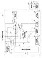
図1は、本発明の実施の形態1に係る無線通信装置の構成を示すブロック図である。
(Embodiment 1)
[Configuration of transmitter]
FIG. 1 is a block diagram showing a configuration of a radio communication apparatus according to
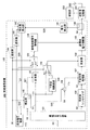
図1に示すように、本発明の実施の形態1に係る無線通信装置200は、送信装置100、送受信切換器201、アンテナ202及び受信部203を具備している。
As shown in FIG. 1, radio communication apparatus 200 according to
送信装置100は、振幅位相分離部101、補正部120、掛算器102、スイッチ103、振幅変調信号増幅器104、高周波電力増幅器105、周波数シンセサイザ106、可変利得増幅器107、掛算器108、下限値制限回路109、スイッチ110、加算器111及び直流電圧電源115を具備している。
The
振幅位相分離部101は、ベースバンド変調信号S0を受けてベースバンド振幅変調信号S1とベースバンド位相変調信号S2とに分離する。掛算器102は、振幅位相分離部101からのベースバンド振幅変調信号S1の値(電圧値)と補正部120からの振幅変調制御信号S21の値(電圧値)とを掛算する。スイッチ103は、モード切換信号S6に基づいて切換制御される。以下、信号の値は、電圧値を示すものとする。
The amplitude
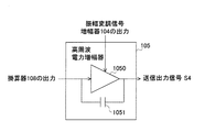
振幅変調信号増幅器104は、高周波電力増幅器105に電源電圧を供給する。高周波電力増幅器105は、掛算器108からの出力信号を電力増幅して送信出力信号S4を出力する。周波数シンセサイザ106は、ベースバンド位相変調信号S2で搬送波信号を位相変調して高周波位相変調信号S3を生成する。可変利得増幅器107は、高周波位相変調信号S3の信号レベルを調整する。
The amplitude
掛算器108は、可変利得増幅器107の出力信号の値とベースバンド振幅変調信号S1の値とを掛算する。下限値制限回路109は、ベースバンド振幅変調信号S1の振幅変動の下限値を制限する。スイッチ110は、モード切換信号S6により切換制御される。加算器111は、可変利得制御信号S20の値と利得オフセット信号S8の値とを加算する。
The
補正部120は、利得制御信号S5とモード切換信号S6とを受ける。補正部120は、利得制御信号S5とモード切換信号S6とに基づき補正テーブル(図2に示す符号121を付けて示す。)を参照し、可変利得制御信号S20と振幅変調制御信号S21とを出力する第1のモードと、可変利得制御信号S20と直流電圧源制御信号S22とを出力する第2のモードと、を有する。直流電圧源制御信号S22は、直流電圧電源115に入力される。
補正部120は、図2に示すような補正テーブル121を備えている。補正テーブル121は、要求電力値125、モード番号126、領域番号127、第1の補正データ128及び第2の補正データ129を有する情報を格納している。要求電力値125としては、利得制御信号S5に対応した値(dBm)が格納されている。モード番号126としては、第1のモードと第2のモードとを区別するための情報が格納されている。領域番号127としては、図3に示すように、送信装置100の特性を複数の領域に区分けして補正を行う場合の領域番号の情報が格納されている。
The
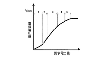
図3は、要求電力値に対し、その要求電力を出力するために必要な高周波電力増幅器105の電源電圧値を示している。図3において、横軸は要求電力値を示し、縦軸は出力電圧値を示す。図3に示すように、要求電力値と高周波電力増幅器105の電源電圧値との関係が線形な領域において区分して、これらの領域区分範囲ごとに所定の補正を行う。このようにすることにより、各要求電力値ごとに個別に補正を行う場合と比較して、補正値の更新を行う時に更新を行う補正値の数が領域区分範囲の数に依存するため(1つの領域区分範囲では一定の補正値)、補正値の更新を行う時間が短くなる。
FIG. 3 shows the power supply voltage value of the high-
第1の補正データ128としては、可変利得制御信号S20の補正値(電圧V)の情報が格納されている。第2の補正データ129としては、第1のモードにおいて振幅変調制御信号S21の補正値(電圧V)の情報が格納され、第2のモードにおいて直流電圧源制御信号S22の補正値(電圧V)が格納されている。
As the
なお、補正テーブル121は、第2の補正データ129を有しないように構成されてもい。また、実施の形態1においては、図3に示すように、送信装置100の特性を複数の領域に区分けして補正することとしたが、このような区分けした補正を行なわずにすべてをひとつの領域として補正してもよい。この場合には、補正テーブル121から領域番号127の情報(項目)は削除される。これにより、補正テーブル121の情報量を減少することができるので、補正テーブル121を構築するメモリ容量を減少することができる。 補正部120は、図4に示すように、前述の補正テーブル121及びスイッチ131を備えている。
The correction table 121 may be configured not to include the
[送信装置の動作]
次に、前述の送信装置100の動作を説明する。図1に示す送信装置100において、高周波電力増幅器105の動作モードは、例えば無線基地局から送信装置100への送信電力レベル指定又は送信装置100の受信信号の状態に基づく送信電力レベルに応じて決定される。送信出力信号S4のレベルが大きい場合は、高周波電力増幅器105が非線形増幅器となる動作モード(第1のモード)になることが電力効率の観点から好ましい。一方、送信出力信号S4のレベルが低くなり高周波電力増幅器105が非線形増幅器として動作可能な範囲から外れる場合、高周波電力増幅器105が線形増幅器となる動作モード(第2のモード)において動作させることが好ましい。
[Transmission Device Operation]
Next, the operation of the
補正部120は、高周波電力増幅器105の平均出力電力の補正を行なうものである。次に、補正部120の動作について詳細に説明する。
The
まず最初に、モード切換信号S6及び利得制御信号S5が補正部120に入力される。利得制御信号S5は、補正部120において補正テーブル121の要求電力値125と比較され、モード切換信号S6は補正テーブル121のモード番号126と比較される。比較の結果、双方とも一致した場合、補正テーブル121の同一列の第1の補正データ128と第2の補正データ129とが補正テーブル121から出力される。
First, the mode switching signal S6 and the gain control signal S5 are input to the
第1の補正データ128は可変利得制御信号S20として出力される。また、第1のモードにおいて、モード切換信号S6によりスイッチ131(図4参照)の端子aと端子cとの間が接続され、第2の補正データ129はスイッチ131を通して振幅変調制御信号S21として出力される。
The
第2のモードにおいて、モード切換信号S6によりスイッチ131の端子bと端子cとの間が接続され、第2の補正データ129はスイッチ131を通して直流電圧源制御信号S22として出力される。
In the second mode, the terminal b and the terminal c of the
次に、補正部120における補正テーブル121の補正値の決定動作について説明する。補正テーブル121に格納される情報の格納(入力)は外部から行われる。ここで、外部とは、例えば送信装置100又は無線通信装置200の外部機器という意味で使用され、具体的には送信装置100又は無線通信装置200を製造する工場のデータ書込装置である。まず、事前に実験等により決定された基準値が準備される。
Next, the correction value determination operation of the correction table 121 in the
この基準値に基づき個々の送信装置100において平均送信電力に応じて補正テーブル121の補正値の更新を行い、この更新された補正値は補正テーブル121に格納される情報として保持される。これによって、個々の送信装置100においては、各々の特性に適合する補正テーブル121を備えることができる。
Based on this reference value, each
モード切換信号S6は、所望の送信電力レベルと高周波電力増幅器105の特性とに基づいて設定される。直流電圧S7は、直流電圧電源115から出力される。ここで、送信装置100に入力される利得制御信号S5、モード切換信号S6及び利得オフセット信号S8は、例えば図示しない制御部により設定され供給される。なお、制御部は送信装置100の内部に配設されている。また、制御部は、送信装置100を無線通信装置等に組み込む場合には、無線通信装置の動作を制御する制御部と共用するようにしてもよい。
Mode switching signal S6 is set based on a desired transmission power level and characteristics of high-
最初に、高周波電力増幅器105の送信出力信号S4のレベルが比較的大きい第1のモードの場合を説明する。この時、高周波電力増幅器105は飽和動作又はスイッチング動作領域の非線形増幅器として動作する。ベースバンド変調信号S0は振幅位相分離部101により、ベースバンド振幅変調信号S1とベースバンド位相変調信号S2とに分離される。
First, the case of the first mode in which the level of the transmission output signal S4 of the high-
ベースバンド振幅変調信号S1の値は、掛算器102によって振幅変調制御信号S21の値と掛け合わされ、掛算器102の出力信号はスイッチ103の端子aに入力される。高周波電力増幅器105で振幅変調が行われる場合(送信出力信号S4のレベルが比較的大きい場合)、モード切換信号S6によりスイッチ103の端子aと端子cとの間が接続される。スイッチ103の端子cから出力されたベースバンド振幅変調信号S1の値と振幅変調制御信号S21の値との乗算値は振幅変調信号増幅器104において増幅され、この増幅された信号は高周波電力増幅器105の電源電圧として高周波電力増幅器105に供給される。高周波電力増幅器105においては振幅変調動作が行われる。
The value of the baseband amplitude modulation signal S1 is multiplied by the value of the amplitude modulation control signal S21 by the
ここで、振幅変調信号増幅器104はベースバンド振幅変調信号S1のレベルに応じて電源電圧を高効率に変化することができるので、パルス幅で振幅情報を表すD級増幅器を使用することが好ましい。
Here, since the amplitude
一方、ベースバンド位相変調信号S2は周波数シンセサイザ106に入力される。周波数シンセサイザ106は搬送波信号をベースバンド位相変調信号S2で位相変調した高周波位相変調信号S3を生成して出力する。この高周波位相変調信号S3は、可変利得増幅器107において利得制御信号S9に基づき増幅(又は減衰)された後、掛算器108に出力される。
On the other hand, the baseband phase modulation signal S <b> 2 is input to the
ここで、可変利得増幅器107に入力される利得制御信号S9は、加算器111で可変利得制御信号S20の値に利得オフセット信号S8の値を加算することで得られる。利得オフセット信号S8は、可変利得増幅器107が高周波電力増幅器105を飽和動作又はスイッチング動作領域の非線形増幅器として動作させるのに適した信号レベルに調整するように設定されている。
Here, the gain control signal S9 input to the
送信出力信号S4のレベルが比較的大きい場合、モード切換信号S6によりスイッチ110の端子aと端子cとの間が接続される。このため、下限値制限回路109でベースバンド振幅変調信号S1の振幅変動の下限値を制限した信号が、このスイッチ110を通して掛算器108に与えられる。
When the level of the transmission output signal S4 is relatively high, the mode switching signal S6 connects the terminal a and the terminal c of the
これにより、掛算器108によって可変利得増幅器107の出力信号の値とベースバンド振幅変調信号S1の振幅変動の下限値を制限した信号の値とが掛け合わされた信号が位相変調信号となる。この掛算器108から出力される位相変調信号は高周波電力増幅器105に入力され、位相変調信号の値は振幅変調信号の値と掛け合わされて送信出力信号S4となって高周波電力増幅器105から出力される。
As a result, a signal obtained by multiplying the value of the output signal of the
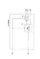
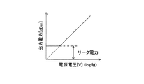
高周波電力増幅器105は、非線形増幅器として動作させた場合、図5に示すように、非線形増幅器1050を備え、更に非線形増幅器1050の入力側と出力側との間に寄生容量1051が付加される。非線形増幅器1050においては、図6に示すように、電源電圧の2乗と出力電力とは比例する。ここで、リーク電力の大きさは、寄生容量1051と非線形増幅器1050の入力信号のレベル(掛算器108の出力信号のレベル)とにより定められている。
When the high
ここで、可変利得増幅器107と掛算器108とを配設しない場合には、周波数シンセサイザ106の出力レベルはほぼ一定であるからリーク電力も一定となる。送信出力信号S4のレベルを下げるためには、非線形増幅器1050の電源電圧を下げればよいが、リーク電力に制限され、一定値よりレベルを下げることができない。
Here, when the
一方、実施の形態1においては、利得制御信号S9により可変利得増幅器107の利得を制御して、高周波電力増幅器105に入力される位相変調信号のレベルを制御することにより、リーク電力を低減することができる。従って、高周波電力増幅器105において、電源電圧による出力電力の制御範囲を拡大することができる。このように、振幅変調信号の平均出力を設定する利得制御信号S5に基づいてベースバンド位相変調信号S2を増幅することにより、可変利得増幅器107によるレベル制御が振幅変調信号の平均電力に追従することができる、すなわち、高周波電力増幅器105の入力を平均出力電力に応じて制御することができる。
On the other hand, in the first embodiment, the leakage power is reduced by controlling the gain of
更に、掛算器108で可変利得増幅器107の出力信号の値をベースバンド振幅変調信号S1の値と掛け合わせることにより、高周波電力増幅器105の入力レベルは振幅変調信号の瞬時レベル変動に追従し、リーク電力も低減することができるので、瞬時レベル変動の再現性を向上することができる。すなわち、高周波電力増幅器105の入力を瞬時出力電力に応じて制御することができる。
Further, by multiplying the value of the output signal of the
ここで、高周波電力増幅器105の入力レベルを下げすぎると、飽和動作又はスイッチング動作領域の範囲から外れ、電源電圧の変化に対する線形性が劣化する。そこで、下限値制限回路109を配設して高周波電力増幅器105の入力レベルを一定値以上に保持している。なお、掛算器108においては、送信出力信号S4に振幅変調を掛けるのではなく、振幅変動に追従してリーク電力を低減すればよいので、瞬時レベル変動の低レベル側が制限されても特性上問題にはならない。
Here, if the input level of the high-
次に、送信出力信号S4のレベルが比較的小さい第2のモードの場合を説明する。この時、高周波電力増幅器105は入出力関係が線形な線形増幅器として動作する。まず、スイッチ103において、モード切換信号S6により端子bと端子cとの間が接続される。これにより、直流電圧値S7がスイッチ103を介して振幅変調信号増幅器104から入力され、振幅変調信号増幅器104は高周波電力増幅器105に一定の電源電圧を供給する。
Next, the case of the second mode in which the level of the transmission output signal S4 is relatively small will be described. At this time, the high
一方、ベースバンド位相変調信号S2は周波数シンセサイザ106に入力され、周波数シンセサイザ106は搬送波信号をベースバンド位相変調信号S2で位相変調した高周波位相変調信号S3を可変利得増幅器107に出力する。高周波位相変調信号S3は可変利得増幅器107において利得制御信号S9に基づき増幅(又は減衰)され、この可変利得増幅器107の出力は掛算器108に入力される。この場合、利得オフセット信号S8はゼロに設定される。従って、利得制御信号S5(=利得制御信号S9)は加算器111を通して可変利得増幅器107に入力される。
On the other hand, the baseband phase modulation signal S2 is input to the
また、この場合、スイッチ110においては、モード切換信号S6によって端子bと端子cとの間が接続される。従って、ベースバンド振幅変調信号S1がスイッチ110を介して掛算器108に入力される。掛算器108は、可変利得増幅器107で増幅された高周波位相変調信号S3の値とベースバンド振幅変調信号S1の値とを掛け合わせる。高周波電力増幅器105は掛算器108の出力を線形増幅し、高周波電力増幅器105は送信出力信号S4を出力する。
In this case, in the
従って、送信出力信号S4のレベルが小さく、高周波電力増幅器105において飽和動作又はスイッチング動作領域から外れる可能性がある場合、すなわち電源電圧の変化に対する出力電力の線形性が劣化する場合においても、高周波電力増幅器105を線形増幅器として動作させることができるので、入力信号に対する出力信号の線形性を保持することができるとともに、出力電力の制御範囲を広げることができる。
Accordingly, even when the level of the transmission output signal S4 is small and there is a possibility that the high-
このように、実施の形態1によれば、送信出力信号S4のレベルが比較的大きい第1のモードにおいて、高周波電力増幅器105を非線形増幅器1050として動作させ、高周波電力増幅器105に供給される電源電圧により振幅変調及び平均出力レベルの制御を行うことができるとともに、送信出力信号のレベルが比較的小さい第2のモードにおいて、高周波電力増幅器105を線形増幅器として動作させ、高周波電力増幅器105の前段に配設された掛算器108により振幅変調を行い、掛算器108の前段に配設された可変利得増幅器107により平均出力レベルの制御を行うことができ、広い範囲にわたって送信出力信号S4のレベルを制御することができる。
Thus, according to the first embodiment, in the first mode in which the level of the transmission output signal S4 is relatively large, the high-
更に、実施の形態1によれば、送信出力信号S4が大きい場合に高周波電力増幅器105を非線形増幅器として動作させることができるので、電力効率を向上させることができる。
Furthermore, according to the first embodiment, when the transmission output signal S4 is large, the high
更に、実施の形態1によれば、高周波電力増幅器105を非線形増幅器として動作させる場合に、利得制御信号S9により可変利得増幅器107の利得を制御して高周波位相変調信号S3のレベルを可変することができ、リーク電力を低減することができるので、電源電圧による出力電力の制御範囲を拡大することができる。
Furthermore, according to the first embodiment, when the high
更に、実施の形態1によれば、高周波位相変調信号S3の値を掛算器108においてベースバンド振幅変調信号S1の値と掛け合わせることにより、高周波電力増幅器105の入力レベルはベースバンド振幅変調信号S1の瞬時レベル変動に追従し、リーク電力も低減することができるので、瞬時レベル変動の再現性を向上することができる。
Furthermore, according to the first embodiment, the value of the high frequency phase modulation signal S3 is multiplied by the value of the baseband amplitude modulation signal S1 in the
[無線通信装置の構成]
図1に示すように、本発明の実施の形態1に係る無線通信装置200は、前述の送信装置100と、送信装置100の高周波電力増幅器105の出力側に接続され送信出力信号S4が入力される送受信切換器201と、送受信切換器201に接続されたアンテナ202とを備えている。
[Configuration of wireless communication device]
As shown in FIG. 1, radio communication apparatus 200 according to
ここで、無線通信装置200には、例えば携帯電話機、通信機能を有する携帯情報端末等の携帯無線端末装置や、無線基地局に設置された無線通信装置等が、少なくとも含まれている。 Here, the wireless communication device 200 includes at least a mobile wireless terminal device such as a mobile phone and a portable information terminal having a communication function, a wireless communication device installed in a wireless base station, and the like.
[無線通信装置の動作]
次に、前述の無線通信装置200の動作を説明する。ここでは、無線通信装置200は携帯無線端末装置として動作を説明する。
[Operation of wireless communication device]
Next, the operation of the above-described wireless communication apparatus 200 will be described. Here, the operation of radio communication apparatus 200 will be described as a portable radio terminal apparatus.
送信時において、無線通信装置200は、高周波電力増幅器105において電力増幅した送信出力信号S4を送受信切換器201を通してアンテナ202から送信する。
At the time of transmission, the wireless communication apparatus 200 transmits the transmission output signal S4 amplified by the high
一方、受信時において、無線通信装置200は、受信信号をアンテナ202から送受信切換器201に入力し、この送受信切換器201は受信信号を受信部203へ出力する。
On the other hand, at the time of reception, radio communication apparatus 200 inputs a received signal from
なお、実施の形態1においては、平均送信電力に基づき補正部120の補正テーブル121の更新を行うようにしているが、この更新処理を行なわずに基準値をそのまま補正テーブル121に格納してもよい。この場合、1度基準値を決定すれば、個々の送信装置100において同じ基準値を利用することができるので、外部から補正テーブル121に補正値の情報を格納する処理を減少することができる。
In the first embodiment, the correction table 121 of the
このように、実施の形態1によれば、送信装置100又は無線通信装置200に補正部120を備え、この補正部120の補正テーブル121をモード毎に切り換えて高周波電力増幅器105の平均出力電力の補正を行うようにしたので、送信装置100又は無線通信装置200の製品毎の特性のばらつきを減少することができ、また、第1のモードと第2のモードとの切り換えの際の誤差を減少することができるので、精度が高くかつ安定した高周波増幅を実現することができる。
As described above, according to the first embodiment, the
また、実施の形態1によれば、第1のモード及び第2のモードに応じた補正値を補正テーブル121に保持しているため、最適なモード切換が可能となる。 Further, according to the first embodiment, since the correction values corresponding to the first mode and the second mode are held in the correction table 121, optimal mode switching can be performed.
また、実施の形態1によれば、モードごとの補正値を補正テーブル121に保持しているため、複数の切換ポイントを存在させることができるから、常に最適なポイントでモード切換が可能となり、また、第1のモードから第2のモードへの切換ポイントと第2のモードから第1のモードへの切換ポイントとを分けることができるため、モード切換ポイント付近での要求電力に対して必要最低限おモード切換のみで対応することができる。 Further, according to the first embodiment, since the correction value for each mode is held in the correction table 121, a plurality of switching points can exist, so that mode switching can always be performed at an optimum point. Because the switching point from the first mode to the second mode and the switching point from the second mode to the first mode can be separated, the minimum necessary power for the required power near the mode switching point It can be handled only by switching modes.
(実施の形態2)
次に、本発明の実施の形態2について、図面を参照して説明する。図7は、本発明の実施の形態2に係る無線通信装置の構成を示すブロック図である。本発明の実施の形態2においては、本発明の実施の形態1と同じ構成要素には同じ参照符号を付してこれらの説明を省略する。
(Embodiment 2)
Next,
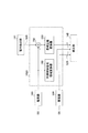
[送信装置及び無線通信装置の構成]
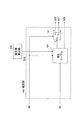
図7に示すように、本発明の実施の形態2に係る送信装置100及びこの送信装置100が組み込みまれた無線通信装置200は、実施の形態1に係る送信装置100及び無線通信装置200に加えて、電力検出部141、補正値算出部142及び補正部145を具備している。電力検出部141は、高周波電力増幅器105から出力される平均出力電力を検出する。補正値算出部142は、電力検出部141において検出された平均出力電力に基づき補正値を算出する。補正部145は、補正テーブル121を有し、この補正テーブル121に格納された補正値を更新する。
[Configuration of transmitter and wireless communication device]
As shown in FIG. 7,
更に、送信装置100及び無線通信装置200は、カップラー140及び遅延器143、144を備えている。カップラー140は、高周波電力増幅器105の出力を取り出す。遅延器143は、利得制御信号S5を遅延調整して補正値算出部142に与える。遅延器144は、モード切換信号S6を遅延調整して補正値算出部142に与える。送信装置100及び無線通信装置200においては、補正部145に具備する補正テーブル121の補正値を更新することができる。
Further, the
補正部145は、図8に示すように、実施の形態2に係る送信装置100及び無線通信装置200の補正部120と基本的には同一構造を備えているが、補正値算出部142を新たに備えているので、補正テーブル121には補正値算出部142から出力される補正テーブル更新値S25が入力されている。
As illustrated in FIG. 8, the
補正値算出部142は、図9に示すように、利得制御信号領域変換器150及び比較器151を備えている。
As shown in FIG. 9, the correction
[送信装置及び無線通信装置の補正制御動作]
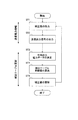
次に、本発明の実施の形態2に係る送信装置100及び無線通信装置200において、高周波電力増幅器105から出力される送信出力信号S4の出力電力の補正制御動作を、図9及び図10を用いて説明する。
[Correction control operation of transmitting apparatus and wireless communication apparatus]
Next, in the
最初に、ステップST1に示すように、利得制御信号S5とモード切換信号S6とを利用し、補正部145から振幅変調制御信号(補正値)S21を出力する。ここで、補正値は初期値であり、この初期値は送信装置100及び無線通信装置200の外部から例えば製品出荷時に与えられる。初期値の設定は、まず事前に実験等により初期値として最適な基準値を準備する。
First, as shown in step ST1, the amplitude control signal (correction value) S21 is output from the
この基準値に基づき、個々の送信装置100及び無線通信装置200は補正部145の補正テーブル121の更新を行い、この更新後の補正テーブル121に格納されたデータが初期値として使用される。初期値は、補正テーブル121の一部又は別途配設された不揮発性メモリ等の記憶装置に格納され、送信装置100又は無線通信装置200のシステム起動時に記憶装置から補正テーブル121に格納される。
Based on this reference value, each transmitting
高周波電力増幅器105においては、ステップST2に示すように、補正部145から出力された補正値に基づき、補正された適正な送信出力信号S4を出力する。
In the high
高周波電力増幅器105から出力された送信出力信号S4は、図7に示すカップラー140を経て送受信切換器201に入力される。ステップST3に示すように、電力検出部141は、カップラー140を介して、送信出力信号S4から平均出力電力データS26をデジタルデータとして測定する。測定された平均出力電力データS26は補正値算出部142に出力される。
The transmission output signal S4 output from the high
補正値算出部142おいては、ステップST4に示すように、平均出力電力データS26と利得制御信号S5とが比較され、補正テーブル更新値S25を算出する。補正値算出部142は、図9に示す比較器151において、電力検出部141から出力される平均出力電力データS26の値と、平均出力電力データS26の測定時に補正部145の参照に利用した利得制御信号S5の値との大きさを比較する。比較器151は、平均出力電力データS26の値が利得制御信号S5の値に対して小さい場合には補正値を上げる「UP」命令を、逆に大きい場合には補正値を下げる「Down」命令を、補正テーブル更新値S25として補正部145に与える。
In the correction
また、利得制御信号S5は、補正テーブル更新値S25の算出に利用され、遅延器143を経て補正値算出部142に入力される。また、利得制御信号S5は、利得制御信号領域変換器150に入力される。利得制御信号領域変換器150は、利得制御信号S5の値を図2に示す補正テーブル121の領域番号127の情報に変換し、この情報を補正部145に与える。モード切換信号S6は、遅延器144を経て補正値算出部142に入力され、そのまま補正テーブル更新値S25として補正部145に与えられる。
The gain control signal S5 is used to calculate the correction table update value S25, and is input to the correction
補正部145は、ステップST5に示すように、補正テーブル更新値S25として「UP」命令を取得した場合には、第1の補正データ128と第2の補正データ129の補正値を固定ステップ分例えば1dBだけ大きくする更新が行われる。また、補正部145は、補正テーブル更新値S25として「Down」命令を取得した場合には、第1の補正データ128の補正値と第2の補正データ129の補正値とを固定ステップ分小さくする更新を行う。すなわち、補正テーブル121の補正値が更新される。
As shown in step ST5, when the “UP” command is acquired as the correction table update value S25, the
これらのステップST1からステップST5の補正制御処理は、補正値算出部142において、平均出力電力データS26と利得制御信号S5とを比較して差が無くなる程度まで充分繰り返し行われる。この補正テーブル121の補正値の更新は連続的に行われる。なお、補正テーブル121の補正値の更新は、必ずしも連続的に行うことに限定されるものではなく、周期的に、又は更新要求が発生した場合に行うようにしてもよい。
The correction control processing from step ST1 to step ST5 is sufficiently repeated in the correction
ここでは、補正テーブル121の初期値を基準値に基づく更新処理により作成した例を説明しているが、基準値をそのまま補正テーブル121の初期値として使用することができる。この場合、一度基準値を設定すれば、複数の送信装置100及び無線通信装置200において、共通した基準値を補正テーブル121の初期値として使用することができ、補正制御処理を減少することができる。
Here, an example is described in which the initial value of the correction table 121 is created by the update process based on the reference value, but the reference value can be used as the initial value of the correction table 121 as it is. In this case, once the reference value is set, the common reference value can be used as the initial value of the correction table 121 in the plurality of
[補正値算出部の変形例]
実施の形態2に係る送信装置100及び無線通信装置200は、図9に示す補正値算出部142に代えて、図11に示す補正値算出部1420を備えるように構成されてもよい。この補正値算出部1420は、加算器152、差補正値変換器153及び利得制御信号領域変換器150を具備している。加算器152は、電力検出部141から出力される平均出力電力データS26の値と遅延器143を経て入力される利得制御信号S5の値とを加算する。差補正値変換器153は、加算器152から出力される出力信号を受ける。
[Modification of Correction Value Calculation Unit]
The
この補正値算出部1420を具備する送信装置100及び無線通信装置200の補正制御動作は、以下のように行われる。
The correction control operations of the
電力検出部141から出力される平均出力電力データS26と、補正部145の参照に利用され遅延器143を経た利得制御信号S5とが補正値算出部1420に入力される。この補正値算出部1420は、加算器152において、平均出力電力データS26の値と利得制御信号S5の値との差を算出する。この算出結果は、加算器152から差補正値変換器153に与えられ、この出力信号に基づき差補正値変換器153は補正値を算出する。
The average output power data S26 output from the
このように構成される図11に示す補正値算出部1420によれば、利得制御信号S5の値と平均出力電力データS26の値との差から送信装置100の特性を推定し補正テーブル121の補正値の更新を行うことができるので、図9に示す補正値算出部142と比較して、補正テーブル121の補正値の更新時間を短縮することができる。
According to the correction
このように、実施の形態2によれば、補正部145において補正テーブル121の補正値の更新を連続的に行い、温度変化等に起因する特性の変化に追従して高周波電力増幅器105の送信出力電力を補正することができるので、高い精度において高周波増幅を実現することができる。
As described above, according to the second embodiment, the correction value in the correction table 121 is continuously updated in the
更に、実施の形態2によれば、平均出力電力を利用して補正テーブル121の補正値の更新を行っているので、振幅や位相を利用した瞬時電力を利用して補正を行う場合に比較して、演算量及びメモリ容量を減少することができるため、送信装置100及び無線通信装置200の回路規模を小さくし、小型化及び軽量化を実現することができる。
Furthermore, according to the second embodiment, since the correction value of the correction table 121 is updated using the average output power, it is compared with the case where the correction is performed using the instantaneous power using the amplitude or phase. Thus, the calculation amount and the memory capacity can be reduced, so that the circuit scales of the
(実施の形態3)
次に、本発明の実施の形態3について、図面を参照して説明する。図12は、本発明の実施の形態3に係る無線通信装置の構成を示すブロック図である。本発明の実施の形態3においては、本発明の実施の形態1、2と同じ構成要素には同じ参照符号を付してこれらの説明を省略する。
(Embodiment 3)
Next,
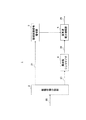
[送信装置及び無線通信装置の構成]
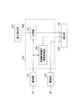
本発明の実施の形態3に係る送信装置100及び無線通信装置200は、図12に示すように、実施の形態2に係る送信装置100及び無線通信装置200のカップラー140に代えて配設されたスイッチ160と、補正部145の前段において利得制御信号S5と補正参照信号S16との入力を切り換えるスイッチ161とを備えている。
[Configuration of transmitter and wireless communication device]
As shown in FIG. 12, transmitting
この送信装置100及び無線通信装置200においては、実施の形態2に係る補正制御動作に加えて、送信電力増幅時と補正テーブル121の補正値の更新時とを切り換えることができる。なお、スイッチ160、161のいずれも、補正制御信号S15により切換制御が行われるようになっている。
In this
[送信装置及び無線通信装置の補正制御動作]
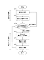
次に、本発明の実施の形態3に係る送信装置100及び無線通信装置200において、高周波電力増幅器105から出力される送信出力信号の出力電力の補正制御動作を、図12及び図13を用いて説明する。
[Correction control operation of transmitting apparatus and wireless communication apparatus]
Next, in
実施の形態3に係る補正制御動作は、基本的には実施の形態2に係る補正制御動作と同様に、ステップST1の補正値の出力段階と、ステップST2の送信出力信号S4の出力段階と、ステップST3の平均出力電力データS26の測定段階からステップST5の補正値の更新段階までとを備え、ステップST2とステップST3との間にステップST10として送信電力増幅処理と補正テーブル更新処理とのいずれかを選択する処理選択段階を更に備えている。 The correction control operation according to the third embodiment is basically the same as the correction control operation according to the second embodiment, the correction value output stage of step ST1, the output stage of the transmission output signal S4 of step ST2, From the measurement stage of the average output power data S26 in step ST3 to the update stage of the correction value in step ST5, and any one of the transmission power amplification process and the correction table update process as step ST10 between step ST2 and step ST3. The process selection stage which selects is further provided.
補正テーブル121の補正値の更新時、すなわち、補正テーブル121の補正値を更新する要求があった場合、ステップST10に示すように、補正制御信号S15がスイッチ160、161のそれぞれに入力される。この補正制御信号S15に基づき、スイッチ160においては端子bと端子cとの間が接続され、スイッチ161においては端子bと端子cとの間が接続される。
When updating the correction values in the correction table 121, that is, when there is a request to update the correction values in the correction table 121, a correction control signal S15 is input to each of the
スイッチ160の切換動作に基づき、高周波増幅器105から出力される送信出力信号S4はスイッチ160を通して電力検出部141に入力され、この電力検出部141において平均出力電力を測定することができる。
Based on the switching operation of the
そして、補正部145には利得制御信号S5の代わりに補正参照信号S16が入力され、この補正参照信号S16に基づき補正テーブル121の補正値を更新することができる。補正テーブル121の補正値の更新は補正制御信号S15に基づく補正値の更新要求があったときのみ行われる。
Then, the correction reference signal S16 is input to the
一方、送信電力増幅時には、補正制御信号S15がスイッチ160、161のそれぞれに入力される。補正制御信号S15に基づき、スイッチ160においては端子aと端子cとの間が接続され、スイッチ161においては端子aと端子cとの間が接続される。スイッチ160の切換動作に基づき、高周波増幅器105から出力される送信出力信号S4はスイッチ160を通して送受信切換器201に入力される。送受信切換器201においては、送信出力信号S4を介してアンテナ202から放射することができる。また、スイッチ161の切換動作に基づき、補正部145には利得制御信号S5が入力される。
On the other hand, at the time of transmission power amplification, the correction control signal S15 is input to each of the
以上説明したように、本発明の実施の形態によれば、高出力電力時には高周波電力増幅器105を非線形増幅器として動作させることができるので、電力効率を向上することができる。また、本発明の実施の形態によれば、特に、電池、バッテリーを電源とする携帯無線端末装置においては、電池やバッテリー等の消耗を防止することができ、使用時間を長くすることができる。また、本発明の実施の形態によれば、高周波電力増幅器105の電力効率を向上することができるので、送信装置100及び無線通信装置200の小型化や軽量化を実現することができる。また、本発明の実施の形態によれば、送信装置100及び無線通信装置200の小型化は、発熱量の低減化を実現することができる。
As described above, according to the embodiment of the present invention, the high
更に、本発明の実施の形態によれば、第1のモードと第2のモード毎とに対応させた2種類の補正値を格納した補正テーブル121に基づき、平均出力電力の補正を行うようにしているので、モード切換時に伴う補正値の誤差をなくし、製品間の特性のばらつきや温度変化に伴う特性の変化を吸収することができる。従って、送信装置100及び無線通信装置200においては、安定した送信出力信号を出力することができる。
Furthermore, according to the embodiment of the present invention, the average output power is corrected based on the correction table 121 that stores two types of correction values corresponding to the first mode and the second mode. Therefore, it is possible to eliminate the error of the correction value associated with the mode switching, and to absorb the characteristic variation between products and the characteristic change accompanying the temperature change. Therefore, the
更に、本発明の実施の形態によれば、大電力が要求される、送信装置100を複数設置する無線システムの基地局装置に適用した場合、高周波電力増幅器105を小型化することができるとともに、発熱量を低減することができるので、設備の大型化を防止することができ、設置スペースを有効に利用することができる。
Furthermore, according to the embodiment of the present invention, when applied to a base station apparatus of a wireless system in which a plurality of
なお、本発明は、上記実施の形態に限定されるものではなく、その要旨を逸脱しない範囲において、種々変更可能である。 In addition, this invention is not limited to the said embodiment, In the range which does not deviate from the summary, various changes are possible.
本発明は、電力効率が良好であり、送信出力電力の制御範囲が広く、かつ安定した電力を出力することができるという効果を有し、携帯電話機、携帯情報端末等の携帯端末装置や、無線基地局等の無線通信装置等に有効である。 INDUSTRIAL APPLICABILITY The present invention has an effect that power efficiency is favorable, a control range of transmission output power is wide, and stable power can be output. This is effective for wireless communication devices such as base stations.
100 送信装置
101 振幅位相分離部
102、108 掛算器
103、110、160、161 スイッチ
104 振幅変調信号増幅器
105 高周波電力増幅器
106 周波数シンセサイザ
107 可変利得増幅器
109 下限値制限回路
111、152 加算器
120、145 補正部
121 補正テーブル
141 電力検出部
142 補正値算出部
143、144 遅延器
140 カップラー
150 利得制御信号領域変換器
151 比較器
153 差補正値変換器
200 無線通信装置
201 送受信切換器
202 アンテナ
DESCRIPTION OF
Claims (8)
前記高周波電力増幅手段の平均出力電力の補正を行なう補正手段と、を備え、
前記送信電力増幅手段は、前記高周波電力増幅器を非線形増幅器として動作させて前記高周波電力増幅器の電源電圧に基づき前記送信信号の振幅変調及び平均出力レベルの制御を行う第1のモードと、前記高周波電力増幅器を線形増幅器として動作させて前記高周波電力増幅器の前段で前記送信信号の振幅変調及び平均出力レベルの制御を行う第2のモードと、を有し、
前記補正手段は、前記平均出力レベルを補正するための補正値の情報を格納している補正テーブルを備え、かつ、前記補正テーブルに格納されている前記補正値の情報に基づいて前記平均出力レベルを補正することを特徴とする送信装置。 A transmission power amplifying means having a high frequency power amplifier for amplifying and outputting a transmission signal;
Correction means for correcting the average output power of the high-frequency power amplification means,
The transmission power amplifying means operates the high-frequency power amplifier as a non-linear amplifier to perform amplitude modulation of the transmission signal and control of an average output level based on a power supply voltage of the high-frequency power amplifier, and the high-frequency power A second mode in which an amplifier is operated as a linear amplifier to perform amplitude modulation of the transmission signal and control of an average output level before the high-frequency power amplifier;
The correction means includes a correction table storing correction value information for correcting the average output level, and the average output level is based on the correction value information stored in the correction table. A transmitter characterized by correcting the above.
前記第2のモードにおいて、前記掛算器は前記送信信号の振幅変調を制御し、かつ、前記可変利得増幅器は前記送信信号の平均出力レベルを制御することを特徴とする請求項1記載の送信装置。 The transmission power amplifying means includes a multiplier disposed in front of the high-frequency power amplifier, and a variable gain amplifier disposed in front of the multiplier,
2. The transmission apparatus according to claim 1, wherein, in the second mode, the multiplier controls amplitude modulation of the transmission signal, and the variable gain amplifier controls an average output level of the transmission signal. .
前記送信装置からの送信信号を受けて無線送信信号を生成して出力するアンテナと、 を具備することを特徴とする無線通信装置。 A transmission device according to claim 1;
An antenna that receives a transmission signal from the transmission device and generates and outputs a wireless transmission signal.
Priority Applications (1)
| Application Number | Priority Date | Filing Date | Title |
|---|---|---|---|
| JP2005064655A JP4583979B2 (en) | 2004-03-09 | 2005-03-08 | Transmitting apparatus and wireless communication apparatus |
Applications Claiming Priority (2)
| Application Number | Priority Date | Filing Date | Title |
|---|---|---|---|
| JP2004065641 | 2004-03-09 | ||
| JP2005064655A JP4583979B2 (en) | 2004-03-09 | 2005-03-08 | Transmitting apparatus and wireless communication apparatus |
Publications (2)
| Publication Number | Publication Date |
|---|---|
| JP2005295523A true JP2005295523A (en) | 2005-10-20 |
| JP4583979B2 JP4583979B2 (en) | 2010-11-17 |
Family
ID=35327900
Family Applications (1)
| Application Number | Title | Priority Date | Filing Date |
|---|---|---|---|
| JP2005064655A Expired - Fee Related JP4583979B2 (en) | 2004-03-09 | 2005-03-08 | Transmitting apparatus and wireless communication apparatus |
Country Status (1)
| Country | Link |
|---|---|
| JP (1) | JP4583979B2 (en) |
Cited By (16)
| Publication number | Priority date | Publication date | Assignee | Title |
|---|---|---|---|---|
| WO2008023414A1 (en) * | 2006-08-23 | 2008-02-28 | Panasonic Corporation | Polar modulation transmission apparatus and polar modulation transmission method |
| WO2008050833A1 (en) * | 2006-10-25 | 2008-05-02 | Panasonic Corporation | Transmission method and transmission device |
| WO2008078565A1 (en) * | 2006-12-26 | 2008-07-03 | Nec Corporation | Power amplifier |
| WO2008084852A1 (en) * | 2007-01-12 | 2008-07-17 | Panasonic Corporation | Transmission power control method and transmission device |
| WO2008084851A1 (en) * | 2007-01-12 | 2008-07-17 | Panasonic Corporation | Transmission device and transmission power control method |
| WO2008090721A1 (en) * | 2007-01-24 | 2008-07-31 | Nec Corporation | Power amplifier |
| JP2010011062A (en) * | 2008-06-26 | 2010-01-14 | Panasonic Corp | Transmitting device and supply voltage setting method |
| WO2011001576A1 (en) * | 2009-07-01 | 2011-01-06 | パナソニック株式会社 | Transmitting circuit and communication apparatus |
| US8064855B2 (en) | 2006-10-25 | 2011-11-22 | Panasonic Corporation | Transmission power controller |
| US8095090B2 (en) | 2006-02-03 | 2012-01-10 | Quantance, Inc. | RF power amplifier controller circuit |
| JP4849571B2 (en) * | 2006-02-03 | 2012-01-11 | クアンタンス, インコーポレイテッド | Power amplifier controller circuit |
| US8179994B2 (en) | 2006-02-03 | 2012-05-15 | Quantance, Inc. | Phase error de-glitching circuit and method of operating |
| US8208876B2 (en) | 2006-02-03 | 2012-06-26 | Quantance, Inc. | Amplifier compression controller circuit |
| US8238853B2 (en) | 2006-02-03 | 2012-08-07 | Quantance, Inc. | Amplitude error de-glitching circuit and method of operating |
| US8340604B2 (en) | 2006-02-03 | 2012-12-25 | Quantance, Inc. | RF power amplifier controller circuit including calibrated phase control loop |
| JP2013539936A (en) * | 2010-09-24 | 2013-10-28 | インテル・コーポレーション | Power calibration under voltage standing wave ratio change by frequency sweep |
Citations (3)
| Publication number | Priority date | Publication date | Assignee | Title |
|---|---|---|---|---|
| JPH06132736A (en) * | 1992-10-19 | 1994-05-13 | Kyocera Corp | Linear transmitter |
| JP2002530917A (en) * | 1998-11-18 | 2002-09-17 | エリクソン インコーポレイテッド | Circuit and method for linearizing amplitude modulation in a power amplifier |
| WO2002084897A2 (en) * | 2001-04-11 | 2002-10-24 | Tropian Inc. | High-quality power ramping in a communications transmitter |
-
2005
- 2005-03-08 JP JP2005064655A patent/JP4583979B2/en not_active Expired - Fee Related
Patent Citations (3)
| Publication number | Priority date | Publication date | Assignee | Title |
|---|---|---|---|---|
| JPH06132736A (en) * | 1992-10-19 | 1994-05-13 | Kyocera Corp | Linear transmitter |
| JP2002530917A (en) * | 1998-11-18 | 2002-09-17 | エリクソン インコーポレイテッド | Circuit and method for linearizing amplitude modulation in a power amplifier |
| WO2002084897A2 (en) * | 2001-04-11 | 2002-10-24 | Tropian Inc. | High-quality power ramping in a communications transmitter |
Cited By (29)
| Publication number | Priority date | Publication date | Assignee | Title |
|---|---|---|---|---|
| JP4849571B2 (en) * | 2006-02-03 | 2012-01-11 | クアンタンス, インコーポレイテッド | Power amplifier controller circuit |
| US8208876B2 (en) | 2006-02-03 | 2012-06-26 | Quantance, Inc. | Amplifier compression controller circuit |
| JP4849572B2 (en) * | 2006-02-03 | 2012-01-11 | クアンタンス, インコーポレイテッド | RF power amplifier controller circuit |
| US8095090B2 (en) | 2006-02-03 | 2012-01-10 | Quantance, Inc. | RF power amplifier controller circuit |
| US8340604B2 (en) | 2006-02-03 | 2012-12-25 | Quantance, Inc. | RF power amplifier controller circuit including calibrated phase control loop |
| US8260225B2 (en) | 2006-02-03 | 2012-09-04 | Quantance, Inc. | Power amplifier controller circuit |
| US8179994B2 (en) | 2006-02-03 | 2012-05-15 | Quantance, Inc. | Phase error de-glitching circuit and method of operating |
| US8238853B2 (en) | 2006-02-03 | 2012-08-07 | Quantance, Inc. | Amplitude error de-glitching circuit and method of operating |
| WO2008023414A1 (en) * | 2006-08-23 | 2008-02-28 | Panasonic Corporation | Polar modulation transmission apparatus and polar modulation transmission method |
| JPWO2008023414A1 (en) * | 2006-08-23 | 2010-01-07 | パナソニック株式会社 | Polar modulation transmission apparatus and polar modulation transmission method |
| JPWO2008050833A1 (en) * | 2006-10-25 | 2010-02-25 | パナソニック株式会社 | Transmission method and transmission apparatus |
| WO2008050833A1 (en) * | 2006-10-25 | 2008-05-02 | Panasonic Corporation | Transmission method and transmission device |
| US8064855B2 (en) | 2006-10-25 | 2011-11-22 | Panasonic Corporation | Transmission power controller |
| JP5109980B2 (en) * | 2006-12-26 | 2012-12-26 | 日本電気株式会社 | Power amplifier |
| WO2008078565A1 (en) * | 2006-12-26 | 2008-07-03 | Nec Corporation | Power amplifier |
| US8072261B2 (en) | 2006-12-26 | 2011-12-06 | Nec Corporation | Power amplifier |
| JP4990295B2 (en) * | 2007-01-12 | 2012-08-01 | パナソニック株式会社 | Transmission power control method and transmission apparatus |
| US8073075B2 (en) | 2007-01-12 | 2011-12-06 | Panasonic Corporation | Transmission apparatus and transmission power control method |
| US7953180B2 (en) | 2007-01-12 | 2011-05-31 | Panasonic Corporation | Transmission power control method and transmission apparatus |
| JPWO2008084852A1 (en) * | 2007-01-12 | 2010-05-06 | パナソニック株式会社 | Transmission power control method and transmission apparatus |
| WO2008084851A1 (en) * | 2007-01-12 | 2008-07-17 | Panasonic Corporation | Transmission device and transmission power control method |
| WO2008084852A1 (en) * | 2007-01-12 | 2008-07-17 | Panasonic Corporation | Transmission power control method and transmission device |
| US7965140B2 (en) | 2007-01-24 | 2011-06-21 | Nec Corporation | Power amplifier |
| WO2008090721A1 (en) * | 2007-01-24 | 2008-07-31 | Nec Corporation | Power amplifier |
| JP5131201B2 (en) * | 2007-01-24 | 2013-01-30 | 日本電気株式会社 | Power amplifier |
| JP2010011062A (en) * | 2008-06-26 | 2010-01-14 | Panasonic Corp | Transmitting device and supply voltage setting method |
| WO2011001576A1 (en) * | 2009-07-01 | 2011-01-06 | パナソニック株式会社 | Transmitting circuit and communication apparatus |
| US8396432B2 (en) | 2009-07-01 | 2013-03-12 | Panasonic Corporation | Transmitter circuit and communication apparatus |
| JP2013539936A (en) * | 2010-09-24 | 2013-10-28 | インテル・コーポレーション | Power calibration under voltage standing wave ratio change by frequency sweep |
Also Published As
| Publication number | Publication date |
|---|---|
| JP4583979B2 (en) | 2010-11-17 |
Similar Documents
| Publication | Publication Date | Title |
|---|---|---|
| US7363014B2 (en) | Transmitting apparatus and radio communication apparatus | |
| JP4583979B2 (en) | Transmitting apparatus and wireless communication apparatus | |
| EP2766989B1 (en) | Apparatus and method for calibration of supply modulation in transmitter | |
| CN101390285B (en) | Polar coordinate modulated transmission device, adaptive distortion compensation processing system, polar coordinate modulated transmission method, and adaptive distortion compensation processing meth | |
| JP5742186B2 (en) | Amplifier | |
| US8577311B2 (en) | Predistortion of amplifier input signals | |
| EP2418767B1 (en) | Amplifying device | |
| US7912148B2 (en) | Transmission circuit and communication device | |
| JP2011188123A (en) | Transmitter circuit using polar modulation method, and communication device | |
| CN102037699A (en) | Distortion compensation circuit and distortion compensation method | |
| JP4608487B2 (en) | Amplifier, information communication device, and amplification method | |
| US20110298536A1 (en) | Distortion compensation amplifier | |
| JP2015099972A (en) | Transmitter module | |
| JP4642068B2 (en) | Transmitting apparatus and wireless communication apparatus | |
| JP2008061231A (en) | Transmission circuit and communication device | |
| JP3874747B2 (en) | Transmission device, transmission power control method, and wireless communication device | |
| JP5488073B2 (en) | Radio apparatus, distortion compensation apparatus, and distortion compensation method | |
| JP2005269440A (en) | Polar modulation transmitter and polar modulation method | |
| US8466755B2 (en) | Polar modulation apparatus and communication device | |
| JPWO2008023414A1 (en) | Polar modulation transmission apparatus and polar modulation transmission method | |
| JP4043824B2 (en) | Nonlinear distortion compensation apparatus and nonlinear distortion compensation method | |
| US7940859B2 (en) | Transmission circuit and communication device | |
| JP2007060455A (en) | Transmitter | |
| JP2011193156A (en) | Radio apparatus, distortion correction device, and distortion correction method | |
| JP5016435B2 (en) | Distortion compensation device |
Legal Events
| Date | Code | Title | Description |
|---|---|---|---|
| A621 | Written request for application examination |
Free format text: JAPANESE INTERMEDIATE CODE: A621 Effective date: 20080109 |
|
| A977 | Report on retrieval |
Free format text: JAPANESE INTERMEDIATE CODE: A971007 Effective date: 20100210 |
|
| A131 | Notification of reasons for refusal |
Free format text: JAPANESE INTERMEDIATE CODE: A131 Effective date: 20100223 |
|
| A521 | Request for written amendment filed |
Free format text: JAPANESE INTERMEDIATE CODE: A523 Effective date: 20100419 |
|
| A131 | Notification of reasons for refusal |
Free format text: JAPANESE INTERMEDIATE CODE: A131 Effective date: 20100601 |
|
| A521 | Request for written amendment filed |
Free format text: JAPANESE INTERMEDIATE CODE: A523 Effective date: 20100722 |
|
| TRDD | Decision of grant or rejection written | ||
| A01 | Written decision to grant a patent or to grant a registration (utility model) |
Free format text: JAPANESE INTERMEDIATE CODE: A01 Effective date: 20100810 |
|
| A01 | Written decision to grant a patent or to grant a registration (utility model) |
Free format text: JAPANESE INTERMEDIATE CODE: A01 |
|
| A61 | First payment of annual fees (during grant procedure) |
Free format text: JAPANESE INTERMEDIATE CODE: A61 Effective date: 20100901 |
|
| R150 | Certificate of patent or registration of utility model |
Free format text: JAPANESE INTERMEDIATE CODE: R150 |
|
| FPAY | Renewal fee payment (event date is renewal date of database) |
Free format text: PAYMENT UNTIL: 20130910 Year of fee payment: 3 |
|
| LAPS | Cancellation because of no payment of annual fees |