JP2005295469A - Monitoring system - Google Patents
Monitoring system Download PDFInfo
- Publication number
- JP2005295469A JP2005295469A JP2004111687A JP2004111687A JP2005295469A JP 2005295469 A JP2005295469 A JP 2005295469A JP 2004111687 A JP2004111687 A JP 2004111687A JP 2004111687 A JP2004111687 A JP 2004111687A JP 2005295469 A JP2005295469 A JP 2005295469A
- Authority
- JP
- Japan
- Prior art keywords
- monitoring system
- video
- monitoring
- detection means
- radio wave
- Prior art date
- Legal status (The legal status is an assumption and is not a legal conclusion. Google has not performed a legal analysis and makes no representation as to the accuracy of the status listed.)
- Pending
Links
Images


Landscapes
- Closed-Circuit Television Systems (AREA)
- Burglar Alarm Systems (AREA)
Abstract
【課題】所定領域を監視するシステムにおいて、侵入者を的確に検知し、無人監視状態であっても、的確なアングル制御やズーミング制御を行ない、侵入者の的確な映像の録画や、低い誤報率で警報を発することの可能な監視システムを提供する。
【解決手段】レーダ等の物体検出手段により所定領域内を移動する物体の位置、移動速度を検出し、その移動パターンから侵入物体であるか否かを判定し、侵入物体であると判定した場合には、侵入物体の行動状態に合わせて監視カメラ等の映像手段のズーミング、フォーカシング、アングルを総合的に制御して侵入物体および、その行動を的確に捉え、VTR等に記録する。それと同時に、前記映像手段の出力信号から侵入物体の画像認識処理を行ない、侵入物体の種類、例えば人であるか否かを判定する。
【選択図】図1[PROBLEMS] To accurately detect an intruder in a system for monitoring a predetermined area, perform accurate angle control and zooming control even in an unattended monitoring state, record an accurate video of the intruder, and have a low false alarm rate. A monitoring system that can issue an alarm is provided.
When the position and moving speed of an object moving within a predetermined area are detected by an object detection means such as a radar, and whether or not the object is an intruding object is determined based on the movement pattern. First, the zooming, focusing, and angle of video means such as a monitoring camera are comprehensively controlled in accordance with the action state of the intruding object, and the intruding object and its action are accurately captured and recorded in a VTR or the like. At the same time, an image recognition process of the intruding object is performed from the output signal of the video means, and it is determined whether the intruding object is, for example, a person.
[Selection] Figure 1
Description
本発明は、監視システムに関し、特に、屋内あるいは屋外において、例えば不審人物等の存在を検知し、その行動を監視する監視システムに関する。 The present invention relates to a monitoring system, and more particularly, to a monitoring system that detects the presence of, for example, a suspicious person indoors or outdoors and monitors its behavior.
従来の監視システムとして、監視領域を撮像する監視カメラを設置して、その映像を直接表示装置に表示し、又はVTR等の映像記録装置に記録し、後にこれを再生して確認する監視カメラシステムがある(例えば、特許文献1参照)。 As a conventional surveillance system, a surveillance camera system for imaging a surveillance area is installed, and the video is directly displayed on a display device, or recorded on a video recording device such as a VTR, and then reproduced and confirmed later. (For example, refer to Patent Document 1).
監視システムは防犯上有効な手段として用いられている。例えば、監視カメラ視野内に動きがあった場合に警報等を行う監視装置では、監視カメラによる背景画像をメモリに記憶してこれを基準とし、以降、監視カメラからの画像をこの背景画像と比較し、差が検出された場合に視野内に動きがあったとして作動するようにしたものがある。 The surveillance system is used as an effective means for crime prevention. For example, in a monitoring device that performs an alarm or the like when there is movement within the surveillance camera field of view, the background image from the surveillance camera is stored in memory and used as a reference, and thereafter the image from the surveillance camera is compared with this background image. However, when a difference is detected, there is one that operates as if there is movement in the visual field.
しかし、従来の監視カメラシステムでは、監視領域内に侵入者があった場合でも、監視カメラの映像にはその人物が小さく撮像されていて、大部分が不要なデータの中から侵入者を抽出、特定することが困難となるおそれがあった。また、視野の明るさが変化した場合にこれを画像の変化であると誤認識したり、鳥や小動物、風に揺らぐ草木などを異常物体として認識したりするという問題があった。
本発明の目的は、上記の問題点を解決し、所定領域において侵入者を的確に検知することができる監視システムを提供することにある。
However, in the conventional surveillance camera system, even when there is an intruder in the surveillance area, the person is imaged small in the video of the surveillance camera, and most of the intruder is extracted from unnecessary data, There was a risk that it would be difficult to specify. In addition, when the brightness of the field of view changes, there is a problem of misrecognizing this as a change in the image, or recognizing a bird, a small animal, a plant that fluctuates in the wind, or the like as an abnormal object.
An object of the present invention is to solve the above-described problems and provide a monitoring system capable of accurately detecting an intruder in a predetermined area.
上記の目的を達成するために本願によって開示される発明のうち代表的なものの概要を簡単に説明すれば、下記のとおりである。
すなわち、本発明の監視システムは、レーダ等の物体検出手段により所定領域内を移動する物体の位置、移動速度を検出し、その移動パターンから侵入物体であるか否かを判定し、侵入物体であると判定した場合には、侵入物体の行動状態に合わせて監視カメラ等の映像手段のズーミング、フォーカシング、アングルを総合的に制御して侵入物体および、その行動を的確に捉え、VTR等に記録する。それと共に、映像手段の出力信号から侵入物体の画像認識処理を行ない、侵入物体の種類、例えば人であるか否かを判定することを特徴とする。
To briefly explain the summary of typical inventions among the inventions disclosed by the present application in order to achieve the above object, it is as follows.
That is, the monitoring system of the present invention detects the position and moving speed of an object moving within a predetermined region by an object detection means such as a radar, determines whether the object is an intruding object from the moving pattern, and When it is determined that there is an intruding object, the zooming, focusing, and angle of the video means such as a surveillance camera are comprehensively controlled according to the action state of the intruding object, and the intruding object and its action are accurately captured and recorded in a VTR or the like To do. At the same time, the image recognition process of the intruding object is performed from the output signal of the video means to determine whether the intruding object is, for example, a person.
具体的には、本発明の監視システムは、所定領域へ向けて電波を放射して、物体からの反射波を受信し、該反射波に基づいて前記物体を検知する物体検出手段と、前記所定領域内の任意の方向の映像を取り込む映像手段とを具備することを特徴とする。
上記の構成において、前記物体検出手段により検知した物体を一定期間監視することにより、前記物体が前記所定領域内に侵入するか否かを判定し、判定した結果に基づいて前記映像手段を制御するようにすれば更に好適である。
Specifically, the monitoring system of the present invention radiates a radio wave toward a predetermined area, receives a reflected wave from the object, and detects the object based on the reflected wave; and the predetermined system And image means for capturing an image in an arbitrary direction within the region.
In the above configuration, the object detected by the object detection unit is monitored for a certain period to determine whether or not the object enters the predetermined region, and the video unit is controlled based on the determination result. This is more preferable.
また、上記構成において、前記物体検出手段により検知した目標物体の位置情報をもとに、前記映像手段を制御し、前記目標物体近辺の画像部分を拡大し、表示装置もしくは録画装置に記録するようにすれば更に好適である。
また、上記構成において、前記映像手段で取り込まれた映像の画像認識処理範囲を、前記物体検出手段により検知した目標物体近辺に限定するようにすれば更に好適である。
In the above configuration, the video means is controlled based on the position information of the target object detected by the object detection means, and the image portion near the target object is enlarged and recorded on the display device or the recording device. If so, it is more preferable.
In the above configuration, it is more preferable that the image recognition processing range of the video captured by the video means is limited to the vicinity of the target object detected by the object detection means.
また、上記構成において、受信した前記反射波の強度に基づいて、前記物体が人体であるか否かを判定するようにすれば更に好適である。
ここで、前記物体検出手段は、ミリ波、準ミリ波、またはマイクロ波を放射するものであってもよいし、モノパルス方式により物体の方位角方向の位置を算出するものであってもよいし、また、屋外を監視するものであってもよい。
In the above configuration, it is more preferable to determine whether the object is a human body based on the intensity of the received reflected wave.
Here, the object detection means may emit a millimeter wave, a quasi-millimeter wave, or a microwave, or may calculate a position in the azimuth direction of the object by a monopulse method. Moreover, it may be one that monitors the outdoors.
本発明によれば、無人監視状態であっても、的確なアングル制御やズーミング制御を行ない、侵入者の的確な映像の録画や、低い誤報率で警報を発することが可能な監視システムを提供できる。 According to the present invention, it is possible to provide a monitoring system capable of performing accurate angle control and zooming control even in an unmanned monitoring state, recording accurate video of an intruder, and issuing an alarm with a low false alarm rate. .
監視領域内を移動する物体を検知し、不審な侵入者であるか否かを判定するという目的を、電波レーダの出力情報により監視カメラを制御することで実現した。 The purpose of detecting an object moving in the monitoring area and determining whether it is a suspicious intruder or not is realized by controlling the monitoring camera with the output information of the radio wave radar.
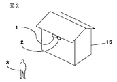
本発明の第1の実施例について説明する。図2は本発明である監視システムを構成する要素のうち、物体検出装置としての電波レーダ装置1と映像手段としての監視カメラ2の設置例を示す。ここでは監視システムの適用例として、戸建住宅の屋外監視を想定した。
A first embodiment of the present invention will be described. FIG. 2 shows an installation example of a radio
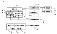
図1は本発明の構成要素間の関わりを表すブロック図を示したものである。電波レーダ装置1は一台で90度以上の広角視野にわたって監視できる機能を果たすものであり、建物から所定の距離を一台あるいは複数台により一望できるような位置に配置される。ここで、電波を用いているので、雨、霧、雪などによる視界不良などが生じていても、的確に侵入物体を検知することができる。電波レーダとしては、例えば、24GHz帯レーダや76GHz帯レーダを用いる。
FIG. 1 is a block diagram showing the relationship between components of the present invention. One
監視カメラ2は、ある的を絞った視野で画像拡大機能を備えて監視・検出をするものであり、雲台5によって垂直・水平方向に駆動制御される。
電波レーダ装置1により物体の監視領域内への侵入を検知すると、監視カメラ2は侵入物体付近の画像を拡大し、映像信号を処理するDSP等からなる画像認識処理部10により、動く部分の外形形状や色から、侵入物体を識別する。そして、人体であると判定された時には、識別した人体の頭部部分を上記の画像拡大手段でさらに拡大し出力するようにすることもできる。
The
When the
次に、図3を用いて、監視システムに用いる電波レーダ装置1の構成について説明する。電波レーダ装置1は、送信系として、変調器16と、発振器17と、送信アンテナ18を備え、受信系として、受信アンテナ19と、ミキサ20と、アナログ回路部21と、A/Dコンバータ22と、FFT(高速フーリエ変換)処理部23とを備えている。
発振器17は、変調器16からの変調信号に基づく発信周波数で発振を行ない、発振された高周波信号が送信アンテナ18から照射波として検知エリアに向けて照射される。
Next, the configuration of the radio
The
次に、電波レーダ装置1におけるレーダの検知原理、すなわち目標物体の距離、移動速度情報検知の原理と出力情報を、2周波CW方式を採用した場合について説明する。
2周波CW方式レーダの場合、発振器17へ変調信号を入力し、図4に示すように、2つの周波数f1,f2を時間的に切替えながら送信する。送信アンテナ18から送信された電波は前方の物体で反射され、反射して返ってきた電波信号は、受信アンテナ19で受信され、ミキサ回路20で周波数変換される。このミキサ回路20には、発信器17からの信号も供給されており、この2つの信号のミキシングによって発生する低周波信号がアナログ回路21へ出力される。アナログ回路21で増幅され、出力された信号は、A/Dコンバータ22によってディジタル信号に変換され、FFT処理部23に送られる。
Next, the radar detection principle in the radio
In the case of a two-frequency CW system radar, a modulation signal is input to the
FFT処理部23で、高速フーリエ変換処理を施し、求められた周波数スペクトルは信号処理部4へ送られる。そこで振幅と位相の情報として計測し、周波数領域の中で信号ピークとして、移動するターゲットを抽出し、以下に説明する原理によって、物体の速度および位置を求める。
信号ピークの周波数は物体の移動によるドップラー周波数となっており、次式でその速度が算出される。
The
The frequency of the signal peak is the Doppler frequency due to the movement of the object, and the velocity is calculated by the following equation.
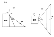
図6は電波レーダ装置1一台の設置形態を示している。図6(a)に示すように電波レーダ装置1は垂直方向に監視角度θ1の監視エリア24を確保している。また、図6(b)に示すように水平方向には監視角度θ2の監視エリア25を確保している。
目標物体追跡回路8は、前記信号処理回路4から入力されるデータに基づいて、検知エリア内への侵入者あるいは侵入物を検知するブロックであり、その処理フローを、図7を用いて説明する。
FIG. 6 shows an installation form of one radio
The target
ステップ26では移動物体が存在するか否かの判断をおこない、存在すると判定した場合はステップ27へ進む。
ステップ27で、移動物体を一定期間監視し、位置・速度を算出し、目標物体の検知座標を位置づけ記憶する。また、目標物体は、移動しているため、時々刻々の目標物体の検知位置も記憶し、追跡・監視する。
ステップ28で移動物体が監視区域内に存在するか否かを判定する。監視区域内であると判定した場合は、ステップ29に進む。
In
In
In
ステップ29では移動物体が監視建物に近づいているか否かを判定する。近づいていると判定した場合はステップ30へ進む。
ステップ30では目標物体の移動速度が人間の出せる範囲内であるか否かを判定し、範囲内であった場合は、不審物体が建物に近づいていると判断する。
In
In
目標物体追跡回路8により不審物体が建物に近づいていると判定された場合、その物体を撮像するために監視カメラ2、雲台5における撮影仰角変更用モータ6と旋回用モータ7に所要の指令や信号を送り、その物体の存在する方向にカメラアングルが移動させられる。
If the target
この物体を撮影中心とするとともに、所要のズーミングをかけることによって、該物体が十分に識別可能な大きさにされる。また、対象物認識のためDSP等からなる画像認識処理部10を起動制御して、監視カメラ2からの出力映像信号の輝度変化等から画像の動き部分を検出する。画像認識処理部10で検出された動き部分から、画像上の物体の場所をさらに狭領域に限定し、侵入物体近辺のデータを新たな映像信号として拡大して読み出す。このように、移動物体に監視カメラをズームインし対象物を撮像するため、画像処理範囲を狭領域に絞り込むことが可能となり、画像処理による認識率が向上する。
By using this object as a photographing center and applying desired zooming, the object can be sufficiently identifiable. In addition, the image
このようにして識別された物体に関する画像情報は、必要に応じて映像記録部11に記録させておき、後での細かい検討のための資料にすることもできる。映像記録部11は、例えばVTR装置のように、関心のある移動物体の存在を示す画像信号を記録するものであり、撮像装置制御部9による制御の下に、監視カメラ2から伝送される画像信号の中で所要のものを記録するようにされる。
Image information relating to the object thus identified can be recorded in the
検知エリア内への人体の侵入は警報装置12や通報装置13に報知され、稼働させる。警報装置12は、監視カメラ2において検知対象としての人体の侵入が検知された場合に、警報音を発する装置である。警報装置13は警報音を生成する音声合成部、音声合成部で生成された警報音を増幅するアンプ部、およびアンプ部からの出力を音声に変換するスピーカ部などによって構成される。通報装置13は、画像認識処理部10において人体の侵入などが検知された場合に、当該セキュリティシステムを管理する管理者や警備者などにその旨を通報する装置である。通報装置13は、例えば無線や有線の通信装置などによって構成される。
The intrusion of the human body into the detection area is notified to the
映像手段としては必要な視野角を有する固定形カメラでもよい。この場合は画面内の不審物体近辺の領域を限定して画像認識処理を行うことにより、不審物体の種類を判別する。
電波レーダ1による距離、速度検知の方式はFM-CW方式やドップラー方式を採用しても同じ効果が得られることは言うまでもない。なお、これらの方式を採用した場合は、静止物体も検知可能となるため、不審物体が移動していなくとも、その存在を検知することができる。
電波レーダ1を筺体ごと回転させることにより、不審な物体の方位角を算出しても良い。
本発明である監視システムは監視カメラを使用する場所などであれば、ホームセキュリティ以外の用途にも使用することができる。
The image means may be a fixed camera having a necessary viewing angle. In this case, the type of the suspicious object is determined by performing the image recognition process by limiting the area near the suspicious object in the screen.
It goes without saying that the same effect can be obtained even if the FM-CW method or the Doppler method is used as the distance and speed detection method by the
The azimuth angle of the suspicious object may be calculated by rotating the
The surveillance system according to the present invention can be used for purposes other than home security if it is a place where a surveillance camera is used.
次に第2の実施例について説明する。一般的に、何らかの物体に対して電波が照射され、その物体が照射された電波を反射した場合、その物体の表面の材料や形状などによって、反射率が異なっている。
また電波レーダ1の受信波電力は電波の送受信点と反射物との距離の4乗に反比例して低減することが知られている。したがって、距離の異なる物体からの受信波電力を単純比較することはできないが、距離に応じた補正を加えることで、物体の反射率を算出することも可能になる。
Next, a second embodiment will be described. In general, when a radio wave is irradiated on a certain object and the irradiated radio wave is reflected, the reflectivity varies depending on the material and shape of the surface of the object.
It is also known that the received wave power of the
目標物体追跡回路8に、侵入物を人体と判定するための基準となる判定値を格納しておき、入力されたデータと上記基準値を比較することにより、接近移動物体が人体であるか否かを判定することもできる。
以上により、カラスやネズミ等の小動物が監視エリアに偶然に入ってきた場合でも、電波レーダの出力情報から、不審な侵入物ではないと判断することができる。
Whether or not the approaching moving object is a human body is stored in the target
As described above, even when a small animal such as a crow or a mouse accidentally enters the monitoring area, it can be determined from the output information of the radio wave radar that it is not a suspicious intruder.
電波レーダ装置1から送信される電波は、プラスチック、布、木材等の電波吸収率の低い材料に対しては、高い透過性を示すので、電波レーダ装置1を屋根付近に埋め込むと共に、送受信アンテナ18、19の前面に壁紙材や壁板材に似せた表面形状の部材を配置することにより、屋根付近の外から見えない箇所に設置することもできる。
この設置方法により電波レーダ1が設置されていることを侵入者に察知されずに監視することができる。
The radio wave transmitted from the radio
With this installation method, it is possible to monitor that the
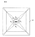
図8は、電波レーダ装置を360°カバーするように多面状に配置した場合の設置方法を示しており、電波レーダ装置1を4個用いた場合に、建物上部から見た監視エリア31を示している。図8の監視エリア31に物体が侵入した場合、電波レーダ装置1により、建物の位置に対する物体の相対速度と侵入場所を検出することができる。
本実施例によれば、レーダ装置を多面状に複数個配置することで、建物の周囲360°を検知エリアとしてカバーできる。
FIG. 8 shows an installation method in the case where the radio wave radar apparatus is arranged in a multi-sided manner so as to cover 360 °, and shows a
According to the present embodiment, by arranging a plurality of radar devices in a multi-surface shape, it is possible to cover 360 ° around the building as a detection area.
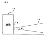
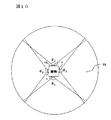
図9は、電波レーダ装置1を建物の側面に設置し、地面に平行に電波を照射する例を示している。
本実施例によれば、図10に示すように、建物の周囲の侵入禁止領域を全て監視エリアとしてカバーすることができる。
FIG. 9 shows an example in which the radio
According to the present embodiment, as shown in FIG. 10, the intrusion prohibited area around the building can be covered as a monitoring area.
本発明の監視システムは、屋内あるいは屋外において、例えば不審人物等の存在を検知し、その行動を監視する防犯管理システムへの産業上の利用可能性を有する。 The monitoring system of the present invention has industrial applicability to a crime prevention management system that detects the presence of, for example, a suspicious person or the like indoors or outdoors and monitors their behavior.
1 電波レーダ装置
2 監視カメラ
3 電波レーダ
4 信号処理回路
5 雲台
6 撮影仰角変更用モータ
7 旋回用モータ
8 目標物体追跡回路
9 撮像装置制御部
10 画像認識処理部
11 映像記憶部
12 警報装置
13 通報装置
14 撮影の対象となる人物
15 建物
16 変調器
17 発振器
18 送信アンテナ
19 受信アンテナ
20 ミキサ
21 アナログ回路
22 A/Dコンバータ
23 FFT処理部
24 電波照射領域
25 電波照射領域
31 実施例4による電波照射領域
32 実施例5による電波照射領域
33 実施例5による電波照射領域。
DESCRIPTION OF
Claims (8)
前記所定領域内の任意の方向の映像を取り込む映像手段と
を具備することを特徴とする監視システム。 Object detection means for radiating radio waves toward a predetermined area, receiving a reflected wave from the object, and detecting the object based on the reflected wave;
A monitoring system comprising video means for capturing video in an arbitrary direction within the predetermined area.
前記物体検出手段により検知した物体を一定期間監視することにより、前記物体が前記所定領域内に侵入するか否かを判定し、判定した結果に基づいて前記映像手段を制御することを特徴とする監視システム。 In claim 1,
The object detected by the object detecting means is monitored for a certain period to determine whether or not the object enters the predetermined area, and the video means is controlled based on the determined result. Monitoring system.
前記物体検出手段により検知した目標物体の位置情報をもとに、前記映像手段を制御し、前記目標物体近辺の画像部分を拡大し、表示装置もしくは録画装置に記録することを特徴とする監視システム。 In claim 1,
A monitoring system that controls the video means based on the position information of the target object detected by the object detection means, enlarges an image portion near the target object, and records it on a display device or a recording device. .
前記映像手段で取り込まれた映像の画像認識処理範囲を、前記物体検出手段により検知した目標物体近辺に限定することを特徴とする監視システム。 In claim 1,
A monitoring system, wherein an image recognition processing range of a video captured by the video means is limited to the vicinity of a target object detected by the object detection means.
受信した前記反射波の強度に基づいて、前記物体が人体であるか否かを判定することを特徴とする監視システム。 In claim 1,
A monitoring system that determines whether or not the object is a human body based on the intensity of the received reflected wave.
前記物体検出手段は、ミリ波、準ミリ波、またはマイクロ波を放射することを特徴とする監視システム。 In any one of Claims 1 thru | or 5,
The object detection means emits millimeter waves, quasi-millimeter waves, or microwaves.
前記物体検出手段は、モノパルス方式により物体の方位角方向の位置を算出することを特徴とする監視システム。 In any one of Claims 1 thru | or 5,
The monitoring system characterized in that the object detection means calculates the position of the object in the azimuth direction by a monopulse method.
前記物体検出手段は、屋外を監視することを特徴とする監視システム。
In any one of Claims 1 thru | or 5,
The object detection means monitors the outdoors, The monitoring system characterized by the above-mentioned.
Priority Applications (1)
| Application Number | Priority Date | Filing Date | Title |
|---|---|---|---|
| JP2004111687A JP2005295469A (en) | 2004-04-06 | 2004-04-06 | Monitoring system |
Applications Claiming Priority (1)
| Application Number | Priority Date | Filing Date | Title |
|---|---|---|---|
| JP2004111687A JP2005295469A (en) | 2004-04-06 | 2004-04-06 | Monitoring system |
Publications (1)
| Publication Number | Publication Date |
|---|---|
| JP2005295469A true JP2005295469A (en) | 2005-10-20 |
Family
ID=35327866
Family Applications (1)
| Application Number | Title | Priority Date | Filing Date |
|---|---|---|---|
| JP2004111687A Pending JP2005295469A (en) | 2004-04-06 | 2004-04-06 | Monitoring system |
Country Status (1)
| Country | Link |
|---|---|
| JP (1) | JP2005295469A (en) |
Cited By (17)
| Publication number | Priority date | Publication date | Assignee | Title |
|---|---|---|---|---|
| WO2007015515A1 (en) * | 2005-08-04 | 2007-02-08 | Optex Co., Ltd. | Intrusion sensor |
| JP2007221581A (en) * | 2006-02-17 | 2007-08-30 | Toshiba Corp | Surveillance system and image processing apparatus |
| JP2009075775A (en) * | 2007-09-19 | 2009-04-09 | Hitachi Kokusai Electric Inc | Monitoring device |
| JP2009526994A (en) * | 2006-02-17 | 2009-07-23 | サイエンス エンジニアリング アンド テクノロジー アソシエーツ コーポレーション | Radar equipment and processing method for detecting a human portable explosive device |
| JP2010176561A (en) * | 2009-01-30 | 2010-08-12 | Equos Research Co Ltd | Security system |
| JP2011165107A (en) * | 2010-02-15 | 2011-08-25 | Let's Corporation | Monitoring system |
| US9055201B2 (en) | 2011-10-14 | 2015-06-09 | Samsung Techwin Co., Ltd. | Apparatus and method of storing and searching for image |
| JP2017167870A (en) * | 2016-03-17 | 2017-09-21 | セコム株式会社 | Flying object monitoring system, and flying object monitoring apparatus |
| JP2020005120A (en) * | 2018-06-28 | 2020-01-09 | セコム株式会社 | Monitoring device |
| JP2020005121A (en) * | 2018-06-28 | 2020-01-09 | セコム株式会社 | Monitoring device |
| CN112565584A (en) * | 2019-09-25 | 2021-03-26 | 深圳市超捷通讯有限公司 | Target shooting device and method |
| US20210319678A1 (en) * | 2013-12-13 | 2021-10-14 | CARRIER Fire & Security Americas Corporation, Inc. | Selective intrusion detection systems |
| JP2022114383A (en) * | 2021-01-26 | 2022-08-05 | 株式会社東芝 | Monitoring device and monitoring method |
| CN115174767A (en) * | 2022-05-27 | 2022-10-11 | 青岛海尔科技有限公司 | Video recording method, edge device, monitoring system and storage medium |
| JP2023163681A (en) * | 2022-04-28 | 2023-11-10 | 日本無線株式会社 | Target object identification device, monitoring system, and target object identification method |
| WO2024203895A1 (en) * | 2023-03-24 | 2024-10-03 | i-PRO株式会社 | Monitoring device and monitoring system |
| WO2025197357A1 (en) * | 2024-03-22 | 2025-09-25 | i-PRO株式会社 | Monitoring system, radar device, and method for controlling monitoring system |
-
2004
- 2004-04-06 JP JP2004111687A patent/JP2005295469A/en active Pending
Cited By (23)
| Publication number | Priority date | Publication date | Assignee | Title |
|---|---|---|---|---|
| JP2007040895A (en) * | 2005-08-04 | 2007-02-15 | Optex Co Ltd | Crime preventive sensor |
| WO2007015515A1 (en) * | 2005-08-04 | 2007-02-08 | Optex Co., Ltd. | Intrusion sensor |
| JP2007221581A (en) * | 2006-02-17 | 2007-08-30 | Toshiba Corp | Surveillance system and image processing apparatus |
| JP2009526994A (en) * | 2006-02-17 | 2009-07-23 | サイエンス エンジニアリング アンド テクノロジー アソシエーツ コーポレーション | Radar equipment and processing method for detecting a human portable explosive device |
| JP2009075775A (en) * | 2007-09-19 | 2009-04-09 | Hitachi Kokusai Electric Inc | Monitoring device |
| JP2010176561A (en) * | 2009-01-30 | 2010-08-12 | Equos Research Co Ltd | Security system |
| JP2011165107A (en) * | 2010-02-15 | 2011-08-25 | Let's Corporation | Monitoring system |
| US9055201B2 (en) | 2011-10-14 | 2015-06-09 | Samsung Techwin Co., Ltd. | Apparatus and method of storing and searching for image |
| US20210319678A1 (en) * | 2013-12-13 | 2021-10-14 | CARRIER Fire & Security Americas Corporation, Inc. | Selective intrusion detection systems |
| US11776368B2 (en) * | 2013-12-13 | 2023-10-03 | Utc Fire & Security Americas Corporation, Inc. | Selective intrusion detection systems |
| JP2017167870A (en) * | 2016-03-17 | 2017-09-21 | セコム株式会社 | Flying object monitoring system, and flying object monitoring apparatus |
| JP2020005121A (en) * | 2018-06-28 | 2020-01-09 | セコム株式会社 | Monitoring device |
| JP7086752B2 (en) | 2018-06-28 | 2022-06-20 | セコム株式会社 | Monitoring device |
| JP7176868B2 (en) | 2018-06-28 | 2022-11-22 | セコム株式会社 | monitoring device |
| JP2020005120A (en) * | 2018-06-28 | 2020-01-09 | セコム株式会社 | Monitoring device |
| CN112565584A (en) * | 2019-09-25 | 2021-03-26 | 深圳市超捷通讯有限公司 | Target shooting device and method |
| CN112565584B (en) * | 2019-09-25 | 2023-04-07 | 荷兰移动驱动器公司 | Target shooting device and method |
| JP2022114383A (en) * | 2021-01-26 | 2022-08-05 | 株式会社東芝 | Monitoring device and monitoring method |
| JP2023163681A (en) * | 2022-04-28 | 2023-11-10 | 日本無線株式会社 | Target object identification device, monitoring system, and target object identification method |
| CN115174767A (en) * | 2022-05-27 | 2022-10-11 | 青岛海尔科技有限公司 | Video recording method, edge device, monitoring system and storage medium |
| CN115174767B (en) * | 2022-05-27 | 2024-03-26 | 青岛海尔科技有限公司 | Video recording method, edge equipment, monitoring system and storage medium |
| WO2024203895A1 (en) * | 2023-03-24 | 2024-10-03 | i-PRO株式会社 | Monitoring device and monitoring system |
| WO2025197357A1 (en) * | 2024-03-22 | 2025-09-25 | i-PRO株式会社 | Monitoring system, radar device, and method for controlling monitoring system |
Similar Documents
| Publication | Publication Date | Title |
|---|---|---|
| JP3760918B2 (en) | Security system | |
| JP2005295469A (en) | Monitoring system | |
| US8120524B2 (en) | Motion detection systems using CW radar in combination with additional sensors | |
| US7463182B1 (en) | Radar apparatus | |
| JP3521899B2 (en) | Intruder detection method and intruder detector | |
| US6621448B1 (en) | Non-contact radar system for reconstruction of scenes obscured under snow and similar material | |
| EP1365259A1 (en) | detecting system | |
| US20060267764A1 (en) | Object detection sensor | |
| US20110102234A1 (en) | Standoff range sense through obstruction radar system | |
| JP3371900B2 (en) | Intruding object detection method and intruding object detection system | |
| EP1326090A2 (en) | Security system | |
| JP2001509631A (en) | Intruder detection system | |
| KR101507238B1 (en) | Radar apparatus | |
| WO2008002821A1 (en) | Field disturbance sensor utilizing leaky or radiating coaxial cable for a conformable antenna pattern | |
| US7683822B2 (en) | Method and system for remotely detecting metal items | |
| JP4741365B2 (en) | Object detection sensor | |
| JP6644561B2 (en) | Flying object monitoring system | |
| KR20100040822A (en) | System for enforcing illegal parking/stop vehicle | |
| CN111693986A (en) | Target object intrusion detection system | |
| US6169512B1 (en) | Signal wave based detection system and method, with direction dependent transmission parameter | |
| JP2017167870A (en) | Flying object monitoring system, and flying object monitoring apparatus | |
| KR102813593B1 (en) | Virtual fence system for adaptive virtual fence according to on-site situation | |
| JP6679372B2 (en) | Object detection device | |
| JP2005233763A (en) | Aircraft detection device | |
| JP2017181101A (en) | Target object detection device |
Legal Events
| Date | Code | Title | Description |
|---|---|---|---|
| RD04 | Notification of resignation of power of attorney |
Effective date: 20060424 Free format text: JAPANESE INTERMEDIATE CODE: A7424 |