JP2005295464A - Optical transmission system - Google Patents
Optical transmission system Download PDFInfo
- Publication number
- JP2005295464A JP2005295464A JP2004111552A JP2004111552A JP2005295464A JP 2005295464 A JP2005295464 A JP 2005295464A JP 2004111552 A JP2004111552 A JP 2004111552A JP 2004111552 A JP2004111552 A JP 2004111552A JP 2005295464 A JP2005295464 A JP 2005295464A
- Authority
- JP
- Japan
- Prior art keywords
- optical
- optical transmission
- port
- transmission line
- standby
- Prior art date
- Legal status (The legal status is an assumption and is not a legal conclusion. Google has not performed a legal analysis and makes no representation as to the accuracy of the status listed.)
- Pending
Links
Images


Landscapes
- Time-Division Multiplex Systems (AREA)
- Optical Communication System (AREA)
Abstract
【課題】 プロテクション機能を提供するとともに、ノードの経済化を図り、ネットワーク構築上の柔軟性を向上させる。
【解決手段】 親ノードは、複数の波長の光送信信号を1つのポートに合波し、1つのポートに入力された受信光信号を複数の波長に分波する波長合分波素子213と、1つのポートを、現用系と前記予備系のポートとの間で接続切替を行う光スイッチ211とを備え、前記子ノードは、現用系と予備系の光伝送路のそれぞれに接続され、各々の子ノードに割り付けられた波長の光信号を合分波するWDMスプリッタ204と、現用系光と予備系の2つのポートを1つのポートに合波する光スプリッタ233と、1つのポートに入力された光送信信号と光受信信号とを2つのポートに合分波するWDMスプリッタ231とを備えた。
【選択図】 図2PROBLEM TO BE SOLVED: To provide a protection function, to make a node economical, and to improve flexibility in network construction.
A parent node multiplexes optical transmission signals of a plurality of wavelengths into one port, and a wavelength multiplexing / demultiplexing element 213 that demultiplexes a received optical signal input to the one port into a plurality of wavelengths; And an optical switch 211 that switches connection between the active system and the standby system port, and the child node is connected to each of the active system and standby system optical transmission lines, WDM splitter 204 that multiplexes and demultiplexes the optical signal of the wavelength assigned to the child node, optical splitter 233 that multiplexes the two ports of the working system light and the protection system into one port, and is input to one port A WDM splitter 231 for multiplexing and demultiplexing the optical transmission signal and the optical reception signal to the two ports is provided.
[Selection] Figure 2
Description
本発明は、光伝送システムに関し、より詳細には、波長分割多重方式を用いた公衆通信網または自営通信網(LAN)に適用され、光伝送路が2重化されたネットワークにおける光伝送システムに関する。 The present invention relates to an optical transmission system, and more particularly, to an optical transmission system in a network that is applied to a public communication network or a private communication network (LAN) using a wavelength division multiplexing system and in which optical transmission lines are duplicated. .
複数のノードが互いに接続された形態の光ネットワークにおいて、ノード間の光伝送路の障害、ノード自体の障害、新規ノードの追加、または既存ノードの挿抜を実施する場合、通信の途絶を防ぐ必要がある。従来、光伝送路または伝送装置を、現用系と予備系の2重化構成とし、または複数の現用系に対して1つの予備系を有するN+1構成として、現用系のシステムを予備系のシステムに一時的に切り替えること(以下、プロテクション機能という)が行われている。 In an optical network in which multiple nodes are connected to each other, it is necessary to prevent communication disruption when performing optical transmission line failure between nodes, failure of the node itself, addition of a new node, or insertion / extraction of an existing node. is there. Conventionally, an optical transmission line or a transmission apparatus has a duplex configuration of an active system and a standby system, or an N + 1 configuration having one standby system for a plurality of active systems, and the active system is changed to a standby system. Switching temporarily (hereinafter referred to as a protection function) is performed.
ポイント−ポイントのネットワークにおいては、両端のノードの伝送装置において現用系と予備系とを切り替える。ポイント−マルチポイントのネットワークにおいては、プロテクション機能としてUPSR(Unidirectional Path Switched Ring)およびBLSR(Bidirectional Line Switched Ring)が知られている(例えば、非特許文献1参照)。UPSRおよびBLSRは、波長分割多重(WDM)伝送方式によるSDH/SONETのリングネットワークに備えられるプロテクション機能である。 In the point-to-point network, the active system and the standby system are switched in the transmission apparatuses at the nodes at both ends. In point-multipoint networks, UPSR (Unidirectional Path Switched Ring) and BLSR (Bidirectional Line Switched Ring) are known as protection functions (see, for example, Non-Patent Document 1). UPSR and BLSR are protection functions provided in an SDH / SONET ring network based on a wavelength division multiplexing (WDM) transmission method.
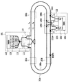
図1に、従来のUPSR型光伝送システムにおけるノードの構成例を示す。UPSR型光伝送システムは、現用系光ファイバ102aと予備系光ファイバ102bからなるリング型光伝送路に、親ノード101と複数の子ノード103a〜103dとが接続されている。親ノード101は、現用系光ファイバ102aと予備系光ファイバ102bとの接続を切り替える1×2ポートの光SW111と、送信信号を現用系光ファイバ102aと予備系光ファイバ102bに分岐する1×2ポートの光スプリッタ112と、2×nポートの波長合分波素子113と、n通りの光波長(λ1,…,λn)の信号を送受信するためのn組の光送受信部114と、光信号の変復調、送受信部の駆動および光SW111の切替制御などを行う制御部115とを備えている。
FIG. 1 shows a configuration example of a node in a conventional UPSR type optical transmission system. In the UPSR type optical transmission system, a
波長合分波素子113は、入力ポートの信号をn本のポートに分波し、n本のポートの信号を出力ポートに合波する。合分波用の素子としては、AWG(Arrayed-Waveguide Grating)がよく知られている(例えば、非特許文献2参照)。光送受信部114のトランスミッタT1,…,Tnからの送信信号は、波長合分波素子113と光スプリッタ112とを介して現用系光ファイバ102aと予備系光ファイバ102bとに送出される。現用系光ファイバ102aからの受信信号は、光SW111と波長合分波素子113とを介して光送受信部114のレシーバR1,…,Rnに入力される。予備系光ファイバ102bからの受信は、制御部115の指示に基づく光SW111の接続切替により行われる。
The wavelength multiplexing /
子ノード103は、予め子ノードに割り付けられた波長(λkとする。kはn以下の自然数)だけを合分波する1×2ポートのWDMスプリッタ131a〜131dと、現用系光ファイバ102aと予備系光ファイバ102bとの接続を切り替える光SW132と、送信信号を現用系光ファイバ102aと予備系光ファイバ102bに分岐する光スプリッタ133と、1組の光送受信部134(Tk、Rk)と、制御部135とを備えている。親ノード101と子ノード103との間で、λkの信号成分だけを送受信し、制御部135からの指示に応じて、親ノード101と同期を取りながら光SW132で切り替えられる。子ノード103の各々は、互いに異なる波長で動作するWDMスプリッタ131を備えることにより、最大、波長数と等しいn台まで配置することができる。
The child node 103 includes 1 × 2
図中に示したように、現用系光ファイバ102aにおいて障害が発生した場合、障害検出信号が各ノードで検出される。親ノード101と子ノード103のそれぞれは、光SW111および光SW132を切り替えて、現用系光ファイバ102aから予備系光ファイバ102bに切り替える。また、人為的に現用系光ファイバ102aから予備系光ファイバ102bに切り替えて、新規ノードの追加、既存のノードの挿抜を行うことにより、短時間の瞬断で追加、挿抜を行うことができる。
As shown in the figure, when a failure occurs in the working
しかしながら、従来のプロテクション機能では、リング型光伝送路の現用系/予備系光ファイバの双方に送信信号を伝搬するため、全ノードに現用系/予備系切替のための光SWと、切替の同期制御を行う制御部とを備える必要があり、伝送装置の経済性という面で問題があった。 However, in the conventional protection function, since the transmission signal is propagated to both the working / standby optical fibers of the ring optical transmission line, the optical SW for switching the working / standby system and the switching synchronization are transmitted to all nodes. It is necessary to provide a control unit that performs control, and there is a problem in terms of economical efficiency of the transmission apparatus.
また、アクセスネットワークのより一般的な形態であるスター型、バス型ネットワークに対しては、上述したように、予備心線を複数の子ノードで共用するプロテクション機能は実現されておらず、子ノードと同数の予備系光ファイバが必要になり、ネットワークの経済性という面で問題があった。 In addition, for the star type and bus type networks which are more general forms of access networks, as described above, the protection function for sharing the spare core wire among a plurality of child nodes is not realized. The same number of spare optical fibers as the above are required, and there is a problem in terms of network economics.
プロテクション機能が付与されないアクセスネットワークでは、サービス提供中に新規ノードの追加、既存のノードの挿抜を行う場合には、サービスの中断が生じる。また、新規ノードの追加が想定される部分には、現時点でのユーザ有の無に関わらず、予め分岐用のWDMスプリッタまたはノードを設けていた。従って、ネットワーク構築上の柔軟性に欠点があった。 In an access network to which a protection function is not provided, service interruption occurs when a new node is added or an existing node is inserted or removed during service provision. In addition, a branching WDM splitter or node is provided in advance at a portion where the addition of a new node is assumed, regardless of whether or not there is a current user. Therefore, there is a drawback in the flexibility of network construction.
本発明は、このような問題に鑑みてなされたもので、その目的とするところは、プロテクション機能を提供するとともに、ノードの経済化を図り、ネットワーク構築上の柔軟性を向上させる光伝送システムを提供することにある。 The present invention has been made in view of such a problem, and an object of the present invention is to provide an optical transmission system that provides a protection function, makes a node economical, and improves flexibility in network construction. It is to provide.
本発明は、このような目的を達成するために、請求項1に記載の発明は、現用系と予備系の光伝送路により、1台の親ノードに接続された複数の子ノードからなり、波長分割多重伝送方式を適用した光伝送システムであって、前記親ノードは、光送信部から入力された複数の波長の光送信信号を1つのポートに合波し、該1つのポートに入力された受信光信号を複数の波長に分波して光受信部に出力する波長合分波素子と、前記1つのポートを、前記現用系光伝送路のポートと前記予備系光伝送路のポートとの間で接続切替を行う光スイッチとを備え、前記子ノードは、前記現用系と予備系の光伝送路のそれぞれに接続され、各々の前記子ノードに割り付けられた波長の光送信信号および光受信信号を合分波する第1のWDMスプリッタと、該第1のWDMスプリッタの前記現用系光伝送路と前記予備系光伝送路の2つのポートを、1つのポートに合波する光スプリッタと、前記1つのポートに入力された光送信信号と光受信信号とを、光送受信部に接続された2つのポートに合分波する第2のWDMスプリッタとを備え、前記親ノードの前記光スイッチを切替えることにより、現用系と予備系とを切替えて通信を行うことを特徴とする。
In order to achieve such an object, the present invention according to
請求項2に記載の発明は、現用系と予備系の光伝送路により、1台の親ノードに接続された複数の子ノードからなり、波長分割多重伝送方式を適用した光伝送システムであって、前記親ノードは、光送信部から入力された複数の波長の光送信信号を1つの送信ポートに合波し、1つの受信ポートに入力された光受信信号を複数の波長に分波して光受信部に出力する波長合分波素子と、前記送信ポートと、前記現用系光伝送路の下り信号ポートと前記予備系光伝送路の下り信号ポートとの間で接続切替を行い、前記受信ポートと、前記現用系光伝送路の上り信号ポートと前記予備系光伝送路の上り信号ポートとの間で接続切替を行う光スイッチとを備え、前記子ノードは、前記現用系と予備系の光伝送路のそれぞれに接続され、各々の前記子ノードに割り付けられた波長の光送信信号および光受信信号を合分波する第1のWDMスプリッタと、該第1のWDMスプリッタの前記現用系光伝送路の下り信号ポートと前記予備系光伝送路の下り信号ポートとを、光受信部に接続された1つのポートに合波し、光送信部に接続された1つのポートを、前記第1のWDMスプリッタの前記現用系光伝送路の上り信号ポートと前記予備系光伝送路の上り信号ポートとに分波する光スプリッタとを備え、前記親ノードの前記光スイッチを切替えることにより、現用系と予備系とを切替えて通信を行うことを特徴とする。
The invention according to
この構成によれば、親ノードの光スイッチを切替えることにより、現用系と予備系とを切替えて通信を行うことができるので、子ノードには光スイッチを備える必要がなく、親ノードと子ノードとの間で切替えのための同期制御を行う必要がない。また、バス型、ツリー型、スター型など様々なネットワークに対応することができ、予め分岐用のWDMスプリッタを設置するだけで、ネットワークの拡張性を確保することができる。 According to this configuration, by switching the optical switch of the parent node, communication can be performed by switching between the active system and the standby system. Therefore, the child node does not need to have an optical switch, and the parent node and the child node There is no need to perform synchronous control for switching between the two. In addition, it can cope with various networks such as a bus type, a tree type, and a star type, and the expandability of the network can be ensured only by installing a branching WDM splitter in advance.
以上説明したように、本発明によれば、プロテクション機能を提供するとともに、ノードの経済化を図り、ネットワーク構築上の柔軟性を向上させることが可能となる。 As described above, according to the present invention, it is possible to provide a protection function, to make a node economical, and to improve flexibility in network construction.
以下、図面を参照しながら本発明の実施形態について詳細に説明する。
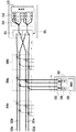
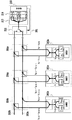
図2に、本発明の第1の実施形態にかかる光伝送システムにおけるノードの構成を示す。光伝送システムは、バス型ネットワークであり、現用系光ファイバ202aと予備系光ファイバ202bからなるバス型光伝送路に、親ノード201と複数の子ノード203とが接続されている。1台の親ノードに、n台(n:自然数)の子ノードを接続することができる。親ノード201は、現用系光ファイバ202aと予備系光ファイバ202bとの接続を切り替える1×2ポートの光SW211と、2n通りの波長の合分波を行う1×2nポートの波長合分波素子213と、2n通りの光波長の信号を送受信するためのn組の光送受信部214と、光信号の変復調、送受信部の駆動および光SW211の切替管理などを行う制御部215とを備えている。
Hereinafter, embodiments of the present invention will be described in detail with reference to the drawings.
FIG. 2 shows a configuration of a node in the optical transmission system according to the first embodiment of the present invention. The optical transmission system is a bus-type network, and a
光送受信部214のトランスミッタT1,…,Tnからの光送信信号(波長λ1,…,λn、以下、下り信号ともいう)は、波長合分波素子213において1ポートに波長多重されて、光SW211に入射される。光送信信号は、光SW211において、通常時は現用系光ファイバ202aに、切替時は予備系光ファイバ202bに結合される。n台の子ノードからの光受信信号(波長λn+1,…,λ2n、以下、上り信号ともいう)は、通常時において、現用系光ファイバ202aを介して光SW211に入射する。光受信信号は、波長合分波素子213に入射され、波長成分毎に分波された後、光送受信部214のレシーバRn+1,…,R2nに結合する。
Optical transmission signals (wavelengths λ 1 ,..., Λ n , hereinafter also referred to as downstream signals) from the transmitters T 1 ,..., T n of the optical transmitter /
制御部215は、子ノードからの信号、外部からの指示により、現用系光ファイバ202aと予備系光ファイバ202bとの切替を行うためのタイミング抽出、切替制御を行う。切替制御について、瞬断の影響をなくすために、各ノード装置内にバッファメモリ、遅延回路等を搭載し、瞬断時間内のデータ保存と再送などの手段を設けることができる。
The
現用系光ファイバ202aと予備系光ファイバ202bの子ノードを接続する箇所には、WDMスプリッタ204a〜204cが接続されている。WDMスプリッタ204a〜204cは、予め子ノードに割り付けられた波長(下り用波長をλkとし、上り用波長をλ1n+kとする)だけを合分波し、残りの波長を下流側の他の子ノードへ伝搬する。
子ノード203は、現用系光ファイバ202aと予備系光ファイバ202bとの間で合分波機能を有する光スプリッタ233と、上り信号と下り信号を波長により分離するWDMスプリッタ231と、1組の光送受信部234(T1n+k、Rk)と、制御部235とを備えている。光送受信部234からの上り信号(波長λ1n+k)は、WDMスプリッタ231を経て光スプリッタ233でパワー分岐され、一部が現用系光ファイバ202aに、残りが予備系光ファイバ202bに結合される。下り信号(波長λk)は、光スプリッタ233で合波された後、WDMスプリッタ231で分離されて、光送受信部234のレシーバRkに結合する。
The
このような構成により、子ノードには、現用系/予備系切替のための光SWを備える必要がなく、制御部から切替の同期制御を行う必要もないので、ノードの経済化を図ることができる。 With such a configuration, the child node does not need to be provided with the optical SW for switching between the active system and the standby system, and it is not necessary to perform the switching synchronous control from the control unit. it can.
図3に、ツリー型ネットワークへの適用例を示す。現用系光ファイバ202aと予備系光ファイバ202bの子ノードを接続する箇所に設置されたWDMスプリッタ204a〜204cにおいて、予め複数の子ノードに割り付けられた波長を合分波し、残りの波長を下流側の他の子ノードへ伝搬する。例えば、波長数n=32とすると、順次、WDMスプリッタ204aにおいては16波ずつ合分波し、WDMスプリッタ204bにおいては8波ずつ合分波し、最後にWDMスプリッタ204eにおいては1波ずつ分岐する。このようにして、ツリー型またはスター型ネットワークに対応することができ、分岐する波長数を任意に選択することにより、様々な形態のネットワークとすることができる。
FIG. 3 shows an application example to a tree-type network. In the
以上述べたように、本実施形態によれば、バス型、スター型いずれのネットワークにも対応することができ、予め分岐用のWDMスプリッタを設置するだけで、ネットワークの拡張性を確保することができる。 As described above, according to the present embodiment, it is possible to cope with both a bus type and a star type network, and it is possible to ensure the expandability of the network simply by installing a branching WDM splitter in advance. it can.
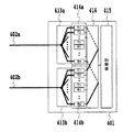
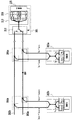
図4に、本発明の第2の実施形態にかかる光伝送システムにおけるノードの構成を示す。光伝送システムは、バス型ネットワークであり、現用系光ファイバ321a,321bと予備系光ファイバ322a,322bからなる4心のバス型光伝送路に、親ノード301と複数の子ノード303とが接続されている。1台の親ノードに、n台(n:自然数)の子ノードを接続することができる。上り信号用と下り信号用の各々に光ファイバを用意することで、上り信号と下利信号の波長を同一波長に設定できるため、全体として必要な波長数を半減することができる。
FIG. 4 shows the configuration of a node in the optical transmission system according to the second embodiment of the present invention. The optical transmission system is a bus-type network, and a
親ノード301は、現用系光ファイバ321と予備系光ファイバ322との接続を切り替える1×2ポートの光SW311と、n通りの波長の合分波を行う2組の1×nポートの波長合分波素子313と、n通りの光波長の信号を送受信するためのn組の光送受信部314と、光信号の変復調、送受信部の駆動および光SW311の切替管理などを行う制御部315とを備えている。
The
光送受信部314のトランスミッタT1,…,Tnからの下り信号(波長λ1,…,λn)は、波長合分波素子313において1ポートに波長多重されて、光SW311に入射される。送信信号は、光SW311において、通常時は現用系光ファイバ321aに、切替時は予備系光ファイバ322aに結合される。n台の子ノードからの受信信号(波長λ1,…,λn)は、通常時において、現用系光ファイバ321bを介して光SW311に入射する。受信信号は、波長合分波素子313に入射され、波長成分毎に分離された後、光送受信部314のレシーバR1,…,Rnに結合する。
Downlink signals (wavelengths λ 1 ,..., Λ n ) from transmitters T 1 ,..., T n of the
現用系光ファイバ321と予備系光ファイバ322の子ノードを接続する箇所には、WDMスプリッタ304a〜304cが接続されている。WDMスプリッタ304a〜304cは、予め子ノードに割り付けられた波長(波長をλk)だけを合分波し、残りの波長を下流側の他の子ノードへ伝搬する。
子ノード303は、合分波機能を有する光スプリッタ333と、1組の光送受信部334(Tk、Rk)と、制御部335とを備えている。光送受信部334からの上り信号(波長λk)は、光スプリッタ333でパワー分岐され、一部が現用系光ファイバ321bに、残りが予備系光ファイバ322bに結合される。下り信号(波長λk)は、光スプリッタ333で合波された後、光送受信部334のレシーバRkに結合する。
The
このような構成により、全体として必要な波長数を半減することができるとともに、子ノードにWDMスプリッタを備える必要がなく、さらなる小型化を図ることができる。 With such a configuration, the number of wavelengths required as a whole can be halved, and the child node does not need to be provided with a WDM splitter, and further miniaturization can be achieved.
図5に、本発明の一実施形態にかかる親ノードの構成を示す。図2に示した親ノード201における光SW211の代わりに、電気的な切替を行う電子SWを備えた。親ノード401は、2組の1×nポートの波長合分波素子413a,413bと、2組の光送受信部414と、2n×1ポートまたは2組の1×nポートからなる電子SW416と、送受信部の駆動および電子SW416を制御する制御部415とを備えている。
FIG. 5 shows a configuration of a parent node according to an embodiment of the present invention. Instead of the
通常時は、現用系光ファイバ402aに接続される光送受信部414aのn本のポートと制御部のポートとが接続されており、切替時は、予備系光ファイバ402bに接続されている光送受信部414bのn本のポートと制御部のポートとが接続されている。光ファイバ心線の切替は、電子SW416によって行われる。
During normal operation, n ports of the optical transmission /
なお、図4に示した4心の光ファイバを使用するバス型光伝送路の場合には、2組の波長合分波素子413a,413bのそれぞれを、2組の1×nポートの波長合分波素子とすることで、現用系/予備系切替を実現することができる。
In the case of a bus-type optical transmission line using the four-core optical fiber shown in FIG. 4, each of the two sets of wavelength multiplexing /
図6に、本発明の一実施形態にかかる子ノードと光伝送路との接続形態を示す。図2に示した接続形態において、子ノード203の光スプリッタ233を、バス型光伝送路の分岐部分にあたるWDMスプリッタ204に内蔵する。このような構成により、バス型光伝送路の分岐部分と子ノードとの間の光ファイバを1心で構成することができる。
FIG. 6 shows a connection form between a child node and an optical transmission line according to an embodiment of the present invention. In the connection form shown in FIG. 2, the
なお、図4に示した4心の光ファイバを使用するバス型光伝送路の場合にも、光スプリッタ333を、バス型光伝送路の分岐部分にあたるWDMスプリッタ304に内蔵することにより、同様の効果を得ることができる。
In the case of the bus type optical transmission line using the four-core optical fiber shown in FIG. 4, the
図7〜9に、子ノードをネットワークに追加するシーケンスを示す。通常時においては、現用系光ファイバ202aがアクティブ状態、すなわち通信が行われている状態である(図7)。子ノードをするために切替の要求が発生した時点で、親ノード201は、切替要求信号を検出する。切替要求信号は、例えば、管理装置を通じたオペレータの指示を制御部215で受信する。制御部215は、光SW211の光ファイバ接続ポートを、予備系光ファイバ202bへ切り替える(図8)。切替により現用系光ファイバ202aは、全ての子ノードに対して遮断され、予備系光ファイバ202bがアクティブ状態となる。
7 to 9 show a sequence for adding child nodes to the network. In a normal time, the active
次に、親ノード201に、追加する子ノード203cと通信を行うための波長を有する光送受信部214のトランスミッタTk+1と、レシーバRn+k+1とが、予め備わっていない場合には追加する。分岐のためのWDM光スプリッタ204cを、現用系光ファイバ202aに挿入して、子ノード203cを物理的に接続する(図8)。この状態で必要に応じて接続確認のために、後述する試験を行うことができる。
Next, when the transmitter T k + 1 and the receiver R n + k + 1 of the optical transmission /
続いて、光SW211の切り戻しにより、現用系光ファイバ202aをアクティブ状態にする(図9)。WDM光スプリッタ204cを、予備系光ファイバ202bに挿入し、同様に接続確認の試験が行って、通常時に戻る。
Subsequently, the active
図10〜12に、光伝送路の障害時における切替のシーケンスを示す。通常時においては、現用系光ファイバ202aがアクティブ状態、すなわち通信が行われている状態である。現用系光ファイバ202aに心線障害が起こると親ノード201で障害検出が行われる(図10)。障害検出は、光送受信部214において、子ノードからの受信信号の信号断または信号強度の低下を検出する。
10 to 12 show a switching sequence when an optical transmission line is faulty. In a normal time, the working
障害を検出すると、制御部215は、光SW211の光ファイバ接続ポートを、予備系光ファイバ202bへ切り替える(図11)。切替により現用系光ファイバ202aは、全ての子ノードに対して遮断され、予備系光ファイバ202bがアクティブ状態となる。現用系光ファイバ202aの障害復旧工事が行われ、施工完了後、接続確認のために、後述する試験を行うことができる。続いて、光SW211の切り戻しにより、現用系光ファイバ202aをアクティブ状態にする(図12)。
When detecting the failure, the
なお、子ノード自体に障害が起きた場合は、挿抜と同様な手順で子ノードを切り離して修復し挿入することで対応が可能である。 If a failure occurs in the child node itself, it can be dealt with by disconnecting the child node, repairing it, and inserting it in the same procedure as the insertion / extraction.
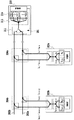
図13に、光伝送路の試験機能を有する親ノードの構成を示す。親ノード601は、2×2ポートの光SW611と、試験部617とを備えている点で、親ノード201と異なる。試験部617は、特定の子ノードの上り送信波長成分だけを抽出する可変波長フィルタ621と、試験用の光受信部であるレシーバ622と、測定部623とを含む。
FIG. 13 shows the configuration of a parent node having an optical transmission line test function. The
通常時の光SW611は、現用系光ファイバ202aと波長合分波素子613との接続、および予備系光ファイバ202bと試験部617との接続を行う。切替時には、逆に現用系光ファイバ202aと試験部617との接続、および予備系光ファイバ202bと波長合分波素子613との接続を行う。
The
例えば、図7〜9に示したように、現用系光ファイバ202aにWDM光スプリッタ204cと子ノード203cとを追加挿入する場合について説明する。光SW611で切替を実施後、現用系光ファイバ202aにWDM光スプリッタ204cを挿入し、子ノード203cより上り試験信号(波長λk)を送出する。現用系光ファイバ202a、光SW611を経て、可変波長フィルタ621により、全ての子ノードの上り信号の中からλk成分だけを抽出する。レシーバ622と測定部623とにより、上り試験信号の信号強度を測定するなどして接続確認を行う。
For example, as shown in FIGS. 7 to 9, a case where a WDM
光SW611を切り戻し後は、予備系光ファイバ202bにWDM光スプリッタ204cを挿入し、同様に子ノード203cより上り試験信号(波長λk)を送出する。上述したように、試験部617にて接続確認を行うことができる。
After switching back the
101,201,301,401,601 親ノード
102a,202a,321,402a,502a 現用系光ファイバ
102b,202b,322,402b,502b 予備系光ファイバ
103,203,303,503 子ノード
111,132,211,311,611 光SW
112,133,233,333,543 光スプリッタ
113,213,313,413,613 波長合分波素子
114,134,214,234,314,334,414,534,614 光送受信部
115,135,215,235,315,335,415,535,615 制御部
131,135,204,231,304,504,533 WDMスプリッタ
416 電子SW
617 試験部
621 可変波長フィルタ
622 レシーバ
623 測定部
101, 201, 301, 401, 601
112, 133, 233, 333, 543
617
Claims (2)
前記親ノードは、
光送信部から入力された複数の波長の光送信信号を1つのポートに合波し、該1つのポートに入力された受信光信号を複数の波長に分波して光受信部に出力する波長合分波素子と、
前記1つのポートを、前記現用系光伝送路のポートと前記予備系光伝送路のポートとの間で接続切替を行う光スイッチとを備え、
前記子ノードは、
前記現用系と予備系の光伝送路のそれぞれに接続され、各々の前記子ノードに割り付けられた波長の光送信信号および光受信信号を合分波する第1のWDMスプリッタと、
該第1のWDMスプリッタの前記現用系光伝送路と前記予備系光伝送路の2つのポートを、1つのポートに合波する光スプリッタと、
前記1つのポートに入力された光送信信号と光受信信号とを、光送受信部に接続された2つのポートに合分波する第2のWDMスプリッタとを備え、
前記親ノードの前記光スイッチを切替えることにより、現用系と予備系とを切替えて通信を行うことを特徴とする光伝送システム。 An optical transmission system composed of a plurality of child nodes connected to one parent node by an active transmission line and a standby optical transmission line, to which a wavelength division multiplexing transmission system is applied,
The parent node is
Wavelength that multiplexes optical transmission signals of a plurality of wavelengths input from the optical transmission unit to one port, demultiplexes the received optical signal input to the one port into a plurality of wavelengths, and outputs the demultiplexed signals to the optical reception unit A multiplexing / demultiplexing element;
An optical switch that switches connection between the port of the working optical transmission line and the port of the standby optical transmission line, the one port;
The child node is
A first WDM splitter that is connected to each of the active and standby optical transmission lines and multiplexes and demultiplexes an optical transmission signal and an optical reception signal of a wavelength assigned to each of the child nodes;
An optical splitter for combining two ports of the working optical transmission line and the standby optical transmission line of the first WDM splitter into one port;
A second WDM splitter that multiplexes and demultiplexes an optical transmission signal and an optical reception signal input to the one port into two ports connected to an optical transmission / reception unit;
An optical transmission system that performs communication by switching between an active system and a standby system by switching the optical switch of the parent node.
前記親ノードは、
光送信部から入力された複数の波長の光送信信号を1つの送信ポートに合波し、1つの受信ポートに入力された光受信信号を複数の波長に分波して光受信部に出力する波長合分波素子と、
前記送信ポートと、前記現用系光伝送路の下り信号ポートと前記予備系光伝送路の下り信号ポートとの間で接続切替を行い、前記受信ポートと、前記現用系光伝送路の上り信号ポートと前記予備系光伝送路の上り信号ポートとの間で接続切替を行う光スイッチとを備え、
前記子ノードは、
前記現用系と予備系の光伝送路のそれぞれに接続され、各々の前記子ノードに割り付けられた波長の光送信信号および光受信信号を合分波する第1のWDMスプリッタと、
該第1のWDMスプリッタの前記現用系光伝送路の下り信号ポートと前記予備系光伝送路の下り信号ポートとを、光受信部に接続された1つのポートに合波し、光送信部に接続された1つのポートを、前記第1のWDMスプリッタの前記現用系光伝送路の上り信号ポートと前記予備系光伝送路の上り信号ポートとに分波する光スプリッタとを備え、
前記親ノードの前記光スイッチを切替えることにより、現用系と予備系とを切替えて通信を行うことを特徴とする光伝送システム。
An optical transmission system composed of a plurality of child nodes connected to one parent node by an active transmission line and a standby optical transmission line, to which a wavelength division multiplexing transmission system is applied,
The parent node is
Optical transmission signals of a plurality of wavelengths input from the optical transmission unit are multiplexed to one transmission port, optical reception signals input to one reception port are demultiplexed into a plurality of wavelengths, and output to the optical reception unit A wavelength multiplexing / demultiplexing element;
Switch connection between the transmission port, the downstream signal port of the working optical transmission line, and the downstream signal port of the standby optical transmission line, and the reception port and the upstream signal port of the working optical transmission line And an optical switch for switching connection between the upstream signal transmission line and the upstream signal port of the backup optical transmission line,
The child node is
A first WDM splitter that is connected to each of the active and standby optical transmission lines and multiplexes and demultiplexes an optical transmission signal and an optical reception signal of a wavelength assigned to each of the child nodes;
The downstream signal port of the working optical transmission line and the downstream signal port of the standby optical transmission line of the first WDM splitter are combined into one port connected to the optical reception unit, and the optical transmission unit An optical splitter that demultiplexes one connected port into an upstream signal port of the active optical transmission line and an upstream signal port of the standby optical transmission line of the first WDM splitter;
An optical transmission system that performs communication by switching between an active system and a standby system by switching the optical switch of the parent node.
Priority Applications (1)
| Application Number | Priority Date | Filing Date | Title |
|---|---|---|---|
| JP2004111552A JP2005295464A (en) | 2004-04-05 | 2004-04-05 | Optical transmission system |
Applications Claiming Priority (1)
| Application Number | Priority Date | Filing Date | Title |
|---|---|---|---|
| JP2004111552A JP2005295464A (en) | 2004-04-05 | 2004-04-05 | Optical transmission system |
Publications (1)
| Publication Number | Publication Date |
|---|---|
| JP2005295464A true JP2005295464A (en) | 2005-10-20 |
Family
ID=35327862
Family Applications (1)
| Application Number | Title | Priority Date | Filing Date |
|---|---|---|---|
| JP2004111552A Pending JP2005295464A (en) | 2004-04-05 | 2004-04-05 | Optical transmission system |
Country Status (1)
| Country | Link |
|---|---|
| JP (1) | JP2005295464A (en) |
Cited By (6)
| Publication number | Priority date | Publication date | Assignee | Title |
|---|---|---|---|---|
| WO2015008512A1 (en) * | 2013-07-16 | 2015-01-22 | 日本電気株式会社 | Transmission device, transmission system, and path-switching method |
| JP2017076944A (en) * | 2015-10-16 | 2017-04-20 | 日本電信電話株式会社 | Optical transmission system, optical transmission method, controlled node, and optical transmission program |
| CN109245982A (en) * | 2017-07-10 | 2019-01-18 | 重庆邮电大学 | A kind of inside and outside network data real-time exchange system based on the stateless end to end connection being unidirectionally divided |
| CN110768725A (en) * | 2018-07-27 | 2020-02-07 | 山东华云光电技术有限公司 | Optical module and optical communication system for unidirectional data transmission |
| CN113541850A (en) * | 2021-07-20 | 2021-10-22 | 烽火通信科技股份有限公司 | A light splitting device, a manufacturing method of the light splitting device, and an optical access system |
| CN118740250A (en) * | 2024-07-23 | 2024-10-01 | 中国移动通信集团辽宁有限公司抚顺分公司 | A three-route optical line protection method based on OLP |
-
2004
- 2004-04-05 JP JP2004111552A patent/JP2005295464A/en active Pending
Cited By (9)
| Publication number | Priority date | Publication date | Assignee | Title |
|---|---|---|---|---|
| WO2015008512A1 (en) * | 2013-07-16 | 2015-01-22 | 日本電気株式会社 | Transmission device, transmission system, and path-switching method |
| JPWO2015008512A1 (en) * | 2013-07-16 | 2017-03-02 | 日本電気株式会社 | Transmission apparatus, transmission system, and path switching method |
| JP2017076944A (en) * | 2015-10-16 | 2017-04-20 | 日本電信電話株式会社 | Optical transmission system, optical transmission method, controlled node, and optical transmission program |
| CN109245982A (en) * | 2017-07-10 | 2019-01-18 | 重庆邮电大学 | A kind of inside and outside network data real-time exchange system based on the stateless end to end connection being unidirectionally divided |
| CN109245982B (en) * | 2017-07-10 | 2020-11-24 | 重庆邮电大学 | A real-time exchange system for internal and external network data based on one-way splitting and stateless end-to-end connection |
| CN110768725A (en) * | 2018-07-27 | 2020-02-07 | 山东华云光电技术有限公司 | Optical module and optical communication system for unidirectional data transmission |
| CN113541850A (en) * | 2021-07-20 | 2021-10-22 | 烽火通信科技股份有限公司 | A light splitting device, a manufacturing method of the light splitting device, and an optical access system |
| CN113541850B (en) * | 2021-07-20 | 2022-04-26 | 烽火通信科技股份有限公司 | Light splitting device, light splitting device manufacturing method and optical access system |
| CN118740250A (en) * | 2024-07-23 | 2024-10-01 | 中国移动通信集团辽宁有限公司抚顺分公司 | A three-route optical line protection method based on OLP |
Similar Documents
| Publication | Publication Date | Title |
|---|---|---|
| JP3008260B2 (en) | Ring network communication structure of optical transmission line and reconfigurable node for that structure | |
| US6532089B1 (en) | Optical cross-connect, method of switching over optical path, optical ADM, and optical cross-connect network system | |
| US6198721B1 (en) | Method and system for data transmission in a ring network | |
| JP3824539B2 (en) | Optical clock signal distribution system for WDM network | |
| JP4176061B2 (en) | Optical network system | |
| JP2001069087A (en) | Addition and erasion arrangement, addition and erasion method and communication system | |
| KR101396954B1 (en) | Optical transmission apparatus and optical transmission system | |
| JP2002223197A (en) | Optical network system with quality control function | |
| JP2006191212A (en) | Optical node and optical add / drop multiplexer | |
| US7447398B2 (en) | Optical crossconnect apparatus | |
| EP1137307A2 (en) | Optical node system and connection method | |
| US20080292310A1 (en) | Method, Apparatus And System For Optical Channel Group Shared Protection | |
| US7877011B2 (en) | Optical switch and optical crossconnect apparatus | |
| US6771907B1 (en) | Optical ring system | |
| US20060250681A1 (en) | Inter-network optical fiber sharing system | |
| EP1411666A2 (en) | Two-fiber optical ring network | |
| JP5681394B2 (en) | Opto-electric hybrid node | |
| EP1715609A1 (en) | An apparauts for implementing optical channel shared protection in wdm system and the method thereof | |
| JP2005295464A (en) | Optical transmission system | |
| JP3475756B2 (en) | Communication network, communication network / node device, and failure recovery method | |
| JP4408542B2 (en) | Optical system | |
| KR100862358B1 (en) | Reconfigurable Optically Coupled Divider | |
| JP2007514380A (en) | Method and system for communicating optical traffic | |
| JP3788263B2 (en) | Communication network, communication network node device, and failure recovery method | |
| JP2004513534A (en) | Method and apparatus for optical channel switching in an optical add / drop multiplexer |