JP2005295216A - Data processing apparatus and program - Google Patents
Data processing apparatus and program Download PDFInfo
- Publication number
- JP2005295216A JP2005295216A JP2004107597A JP2004107597A JP2005295216A JP 2005295216 A JP2005295216 A JP 2005295216A JP 2004107597 A JP2004107597 A JP 2004107597A JP 2004107597 A JP2004107597 A JP 2004107597A JP 2005295216 A JP2005295216 A JP 2005295216A
- Authority
- JP
- Japan
- Prior art keywords
- bits
- bit string
- output
- bit
- input
- Prior art date
- Legal status (The legal status is an assumption and is not a legal conclusion. Google has not performed a legal analysis and makes no representation as to the accuracy of the status listed.)
- Granted
Links
- 238000012545 processing Methods 0.000 title claims abstract description 64
- 230000006870 function Effects 0.000 claims description 4
- 238000012217 deletion Methods 0.000 abstract description 74
- 230000037430 deletion Effects 0.000 abstract description 74
- 238000003780 insertion Methods 0.000 abstract description 73
- 230000037431 insertion Effects 0.000 abstract description 73
- 238000001514 detection method Methods 0.000 abstract description 43
- 238000000034 method Methods 0.000 description 91
- 230000005540 biological transmission Effects 0.000 description 10
- 238000010586 diagram Methods 0.000 description 6
- 238000006243 chemical reaction Methods 0.000 description 5
- 230000002159 abnormal effect Effects 0.000 description 4
- 238000012966 insertion method Methods 0.000 description 4
- 238000012937 correction Methods 0.000 description 2
- 230000001360 synchronised effect Effects 0.000 description 2
- 230000007423 decrease Effects 0.000 description 1
- 230000003247 decreasing effect Effects 0.000 description 1
- 238000000605 extraction Methods 0.000 description 1
- 230000008520 organization Effects 0.000 description 1
- 238000013519 translation Methods 0.000 description 1
Images


Landscapes
- Communication Control (AREA)
Abstract
Description
本発明は、HDLC(High-level Data Link Control Procedure)を用いたデータを処理する装置に関し、特に0挿入及び0削除の高速化を可能にしたデータ処理装置に関する。 The present invention relates to an apparatus for processing data using HDLC (High-level Data Link Control Procedure), and more particularly, to a data processing apparatus capable of speeding up zero insertion and zero deletion.
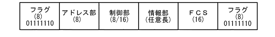
HDLCは、IBM社のSDLC(Synchronous Data Link Control )をベースにISO(国際標準化機構)が定めたデータリンク層の標準規約である。HDLCのフレーム構成は、図25に示すように、フレームの開始及び終了を示す8ビットのフラグと、順次フラグに続く8ビットのアドレス部、8ビット又は16ビットの制御部、任意ビット長の情報部、及び16ビットのFCS(フレーム・チェック・シーケンス)からなる。フラグのビットパターンは01111110と定められているため、フレームの開始と終了を示すフラグに挟まれた部分では、ビット1が5個連続する場合、送信側ではその次にビット0を挿入し(これを0挿入という)、受信側ではそのビット0を削除する(これを0削除という)ことで、フラグのビットパターンの独自性を保証している。
HDLC is a data link layer standard defined by ISO (International Organization for Standardization) based on IBM's SDLC (Synchronous Data Link Control). As shown in FIG. 25, the HDLC frame structure includes an 8-bit flag indicating the start and end of a frame, an 8-bit address part, an 8-bit or 16-bit control part, and an arbitrary bit length information following the sequential flag. And a 16-bit FCS (frame check sequence). Since the bit pattern of the flag is determined to be 01111110, if there are 5
従来、このような0挿入及び0削除を行う方法として、特許文献1に開示された「同期HDLCのためのビット・スタッフィング方法及び装置」がある。以下、図26
乃至51を参照しながら、特許文献1に開示されたビット・スタッフィング方法について説明する。
Conventionally, as a method for performing such zero insertion and zero deletion, there is a “bit stuffing method and apparatus for synchronous HDLC” disclosed in
The bit stuffing method disclosed in
まず、図26のフローチャート及び図27乃至36の状態変化を示す図を用いて0挿入方法を説明する。これらの図において、入力キューはこれから0挿入処理を受けるデータ、出力キューは0挿入処理を受けたデータである。 First, the zero insertion method will be described with reference to the flowchart of FIG. 26 and the diagrams showing the state changes of FIGS. In these figures, an input queue is data that will be subjected to 0 insertion processing, and an output queue is data that has undergone 0 insertion processing.
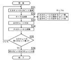
まず、6オクテット(48ビット)入力キューの先頭から1オクテット(8ビット)のデータを選択する(図27(a)、図26ステップS31)。図27(a)において、枠で囲まれた01011011が選択された8ビットを示す。次に、0挿入用テーブルを検索して、(ア)出力キューに付加するビット数(以下、出力ビット数という)、(イ)入力キューから削除するビット数(以下、削除ビット数という)、及び(ウ)出力キューに付加するビット列(以下、出力ビット列という)を読み出す(図27(b)、ステップS32)。0挿入用テーブルには、入力される8ビットの全ての組み合わせ(28 =256通り)に対する上記(ア)、(イ)及び(ウ)のデータが予め格納されている。 First, data of 1 octet (8 bits) is selected from the head of the 6 octet (48 bits) input queue (FIG. 27A, step S31 in FIG. 26). In FIG. 27A, 01011011 surrounded by a frame indicates 8 bits selected. Next, by searching the table for 0 insertion, (a) the number of bits to be added to the output queue (hereinafter referred to as the number of output bits), (b) the number of bits to be deleted from the input queue (hereinafter referred to as the number of deleted bits), And (c) A bit string to be added to the output queue (hereinafter referred to as an output bit string) is read (FIG. 27B, step S32). In the 0 insertion table, the data (a), (b), and (c) for all the input 8-bit combinations (2 8 = 256) are stored in advance.
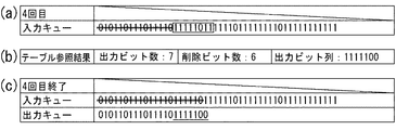
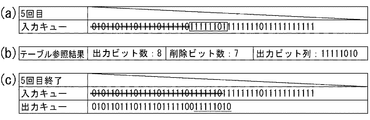
ここでは、出力ビット数=6、削除ビット数=6、出力ビット列=010110である。選択された8ビットが全て入力キューから削除され、かつ出力キューに付加されない理由は、選択された8ビットの末尾の2ビット11は、その2ビットの次に1が3個続いた場合、その次に0挿入処理を行うことになるため、次に選択される先頭の3ビットと併せて処理する必要があり、未確定であるためである。従って、ここでは、出力キューに010110を付加し(ステップS33)、入力キューから010110を削除する(ステップS34)。図27(c)は、010110が削除された入力キュー、及び010110が付加された出力キューを示す。ここで、入力キューの010110に付与された二重線は削除されたビット列を表し、網がけは今回削除されたビット列を表す。また、出力キューに付与された下線は今回付加されたビット列を表す。
Here, the number of output bits = 6, the number of deleted bits = 6, and the output bit string = 010110. The reason why all the selected 8 bits are deleted from the input queue and not added to the output queue is that the last 2
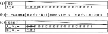
以上のステップS31乃至34を入力キューのビット数が8より小さくなるまで繰り返す(ステップS35)。ここでは、図28(a)に示すように、11101111を選択する。この先頭の11は前回選択されたものの出力キューに付加されなかった2ビットである。テーブルを検索した結果は、図28(b)に示すように、出力ビット数=4、削除ビット数=4、出力ビット列=1110である。従って、図28(c)に示すように、1110が入力キューから削除され、かつ出力キューに付加される。 The above steps S31 to S34 are repeated until the number of bits in the input queue becomes smaller than 8 (step S35). Here, 11101111 is selected as shown in FIG. The leading 11 is 2 bits that were selected last time but were not added to the output queue. As a result of searching the table, as shown in FIG. 28B, the number of output bits = 4, the number of deleted bits = 4, and the output bit string = 1110. Therefore, as shown in FIG. 28C, 1110 is deleted from the input queue and added to the output queue.
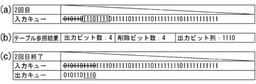
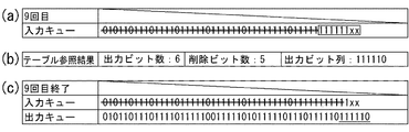
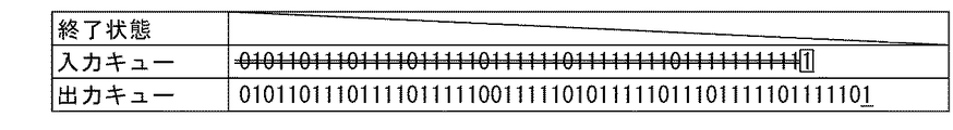
以後、図29乃至図35までステップS31乃至34の処理が繰り返し実行され、図35(c)に示す状態になると、ステップS35で”はい”と判定されるので、1フレームの処理が終わる。図30、31、32、34及び35では0挿入を行っている。なお、図35の入力キューのxxは次のフレームのデータである。 Thereafter, the processing of steps S31 to S34 is repeatedly executed from FIG. 29 to FIG. 35, and when the state shown in FIG. 35C is reached, it is determined “Yes” in step S35, and thus the processing of one frame is completed. In FIGS. 30, 31, 32, 34 and 35, zero insertion is performed. Note that xx in the input queue in FIG. 35 is data of the next frame.
次に、図37及び38のフローチャート及び図39乃至51の状態変化を示す図を用いて0削除方法を説明する。これらの図において、入力キューはこれから0削除処理を受けるデータ、出力キューは0削除処理を受けたデータである。また、図37は開始フラグ検出処理であり、図38は開始フラグ検出後の処理である。 Next, the zero deletion method will be described with reference to the flowcharts of FIGS. 37 and 38 and the diagrams showing the state changes of FIGS. In these figures, the input queue is data that will be subjected to the 0 deletion process, and the output queue is data that has been subjected to the 0 deletion process. FIG. 37 shows the start flag detection process, and FIG. 38 shows the process after the start flag is detected.
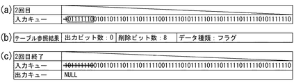
まず、0削除の前にフラグ検出を行うために、入力キューの先頭から1オクテット(8ビット)のデータを選択する(図39(a)、図37ステップS41)。次に、フラグ検出テーブルを検索して、(ア)入力キューから削除するビット数(削除ビット数)、及び(イ)データ種別(フラグ/通常データ)を読み出す(図39(b)、ステップS42)。ここでは、データ種別はフラグではなく、削除ビット数=1である。従って、ステップS43で”いいえ”と判断され、ステップS45で入力キューから先頭の1ビットが削除され、ステップS41に戻る。フラグが検出される迄は出力キューにデータは付加されないので、図39(c)に示すように、1が入力キューから削除され、出力キューに付加されるデータはない。 First, in order to detect a flag before deleting 0, data of 1 octet (8 bits) is selected from the head of the input queue (FIG. 39A, step S41 in FIG. 37). Next, the flag detection table is searched, and (a) the number of bits to be deleted from the input queue (number of deleted bits) and (b) the data type (flag / normal data) are read (FIG. 39 (b), step S42. ). Here, the data type is not a flag, but the number of deleted bits = 1. Accordingly, “NO” is determined in step S43, the first bit is deleted from the input queue in step S45, and the process returns to step S41. Since no data is added to the output queue until the flag is detected, as shown in FIG. 39 (c), 1 is deleted from the input queue and no data is added to the output queue.
再び入力キューから8ビットを選択する。今回は01111110が選択されている(図40(a))。フラグ検出テーブルを検索することにより、入力された8ビットがフラグであり、削除ビット数=8であることが分かる。従って、ステップS43で”はい”と判断され、ステップS44で入力キューからフラグの8ビットが削除され、開始フラグ検出処理を終える。 Again, 8 bits are selected from the input queue. This time, 01111110 is selected (FIG. 40A). By searching the flag detection table, it can be seen that the inputted 8 bits are flags and the number of deleted bits = 8. Accordingly, “Yes” is determined in step S43, and the 8 bits of the flag are deleted from the input queue in step S44, and the start flag detection process is completed.
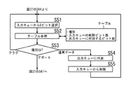
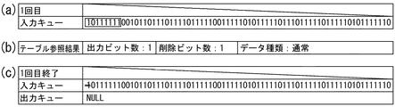
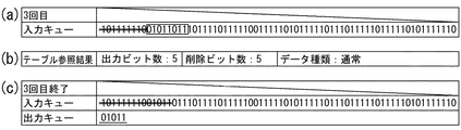
開始フラグが検出されたので、次に図38に示されている0削除処理を実行する。入力キューの先頭から1オクテット(8ビット)のデータを選択する(図41(a)、図38のステップS51)。ここでは、01011011が選択されている。次に、0削除テーブルを検索して、(ア)出力キューに付加するビット数(出力ビット数)、(イ)入力キューから削除するビット数(削除ビット数)、及び(ウ)データ種別(通常データ/フラグ/アボート)を読み出す(図41(b)、ステップS52)。ここでは、図41(b)に示されているように、出力ビット数=5、削除ビット数=5、データ種別=通常データである。選択された8ビットの後部の3ビット011が出力キューに付加されない理由は、この011がフラグの先頭3ビットと同じであるため、その3ビットの次に11110が続いた場合、終了フラグとなるからである。従って、ステップS53”通常データ”と判定され、ステップS54で01011が出力キューに付加され、ステップS55 で01011が入力キューから削除された結果、図41(c)に示す状態となる。
Since the start flag is detected, the zero deletion process shown in FIG. 38 is executed next. Data of 1 octet (8 bits) is selected from the head of the input queue (FIG. 41 (a), step S51 in FIG. 38). Here, 01011011 is selected. Next, the 0 deletion table is searched, and (a) the number of bits to be added to the output queue (output bit number), (b) the number of bits to be deleted from the input queue (deletion bit number), and (c) the data type ( Normal data / flag / abort) is read (FIG. 41 (b), step S52). Here, as shown in FIG. 41B, the number of output bits = 5, the number of deleted bits = 5, and the data type = normal data. The reason why the last 3
以後、図42乃至50迄ステップS51乃至55の処理が繰り返し実行され、図51(a)に示すようにステップS53でフラグが検出され、1フレームの処理が終わる。図44、45、46、48及び49では0削除が行われている。1フレームの処理が終わると、ステップS51に戻って次のフレームの処理を行う。また、ステップS53でアボートが検出された場合は、図37のステップS41に戻ってフラグ検出処理を行う。
しかしながら、上記従来の0挿入方法及び0削除方法では、入力キューから選択したビット列のうち確定したビット数分だけを削除するため、削除処理が複雑になる。また、ビット列の並びにより処理回数が増減し、0挿入方法では特に1が連続すると処理回数が極めて増加し、0削除方法ではフラグの一部と同じビット並びのデータがあるとき、及び0削除が必要なビット列が連続するときに処理回数が多くなり、処理時間が長くなる。 However, in the conventional 0 insertion method and 0 deletion method, only the determined number of bits in the bit string selected from the input queue is deleted, so the deletion process becomes complicated. In addition, the number of processes increases or decreases depending on the arrangement of bit strings. In the 0 insertion method, especially when 1 continues, the number of processes increases extremely. In the 0 deletion method, when there is data having the same bit arrangement as part of the flag, and 0 deletion is When necessary bit strings are continuous, the number of processes increases, and the processing time becomes longer.
本発明はこのような問題点を解決するためになされたもので、0挿入処理又は0削除処理の処理回数が入力キューのビット列の並びに影響を受けないようにして、処理時間を短縮することを目的とする。 The present invention has been made to solve such problems, and it is possible to reduce the processing time by preventing the number of times of zero insertion processing or zero deletion processing from being affected by the arrangement of bit strings in the input queue. Objective.
請求項1に係る発明は、入力キューに0挿入を行い出力キューを生成するデータ処理装置であって、前記入力キューから所定ビット数毎にビット列を選択して入力ビット列とする手段と、前回の入力ビット列と前回の出力ビット列との差異に対応する状態データ、前記所定ビット数のビット列の並び、出力ビット列、及び次回の状態データの組合せが予め記憶されたテーブルを検索して、前記入力ビット列に対応する出力ビット列及び次回の状態データを読み出す手段と、前記出力ビット列を前記出力キューに付加する手段とを備えたことを特徴とするデータ処理装置である。
請求項2に係る発明は、入力キューから0削除を行い出力キューを生成するデータ処理装置であって、前記入力キューから所定ビット数毎にビット列を選択して入力ビット列とする手段と、前回の入力ビット列と前回の出力ビット列との差異に対応する状態データ、前記所定ビット数のビット列の並び、出力ビット列、及び次回の状態データの組合せが予め記憶されたテーブルを検索して、前記入力ビット列に対応する出力ビット列及び次回の状態データを読み出す手段と、前記出力ビット列を前記出力キューに付加する手段とを備えたことを特徴とするデータ処理装置である。
請求項3に係る発明は、入力キューに0挿入を行い出力キューを生成するデータ処理装置のコンピュータを、前記入力キューから所定ビット数毎にビット列を選択して入力ビット列とする手段と、前回の入力ビット列と前回の出力ビット列との差異に対応する状態データ、前記所定ビット数のビット列の並び、出力ビット列、及び次回の状態データの組合せが予め記憶されたテーブルを検索して、前記入力ビット列に対応する出力ビット列及び次回の状態データを読み出す手段と、前記出力ビット列を前記出力キューに付加する手段として機能させることを特徴とするプログラムである。
請求項4に係る発明は、入力キューから0削除を行い出力キューを生成するデータ処理装置のコンピュータを、前記入力キューから所定ビット数毎にビット列を選択して入力ビット列とする手段と、前回の入力ビット列と前回の出力ビット列との差異に対応する状態データ、前記所定ビット数のビット列の並び、出力ビット列、及び次回の状態データの組合せが予め記憶されたテーブルを検索して、前記入力ビット列に対応する出力ビット列及び次回の状態データを読み出す手段と、前記出力ビット列を前記出力キューに付加する手段として機能させることを特徴とするプログラムである。
The invention according to
The invention according to
According to a third aspect of the present invention, there is provided a data processing device computer that inserts 0 into an input queue and generates an output queue, and selects a bit string from the input queue for each predetermined number of bits as an input bit string; Search the table in which the state data corresponding to the difference between the input bit string and the previous output bit string, the arrangement of the bit string of the predetermined number of bits, the output bit string, and the combination of the next state data are stored in advance, and the input bit string A program which functions as means for reading a corresponding output bit string and next state data and means for adding the output bit string to the output queue.
According to a fourth aspect of the present invention, there is provided a data processing device computer that generates an output queue by deleting 0 from an input queue, and selects a bit string from the input queue for each predetermined number of bits as an input bit string; Search the table in which the state data corresponding to the difference between the input bit string and the previous output bit string, the arrangement of the bit string of the predetermined number of bits, the output bit string, and the combination of the next state data are stored in advance, and the input bit string A program which functions as means for reading a corresponding output bit string and next state data and means for adding the output bit string to the output queue.
本発明によれば、入力キューから選択された所定数のビット列は、ビット列の並びに関係なく処理され、出力キューに付加されるので、0挿入処理又は0削除処理の処理回数がビット列の並びに影響を受けなくなり、処理時間が短縮される。 According to the present invention, a predetermined number of bit strings selected from the input queue are processed regardless of the arrangement of the bit strings and added to the output queue, so that the number of times of the 0 insertion process or the 0 deletion process affects the arrangement of the bit strings. Processing time is shortened.
以下、図面を参照しながら本発明の実施形態について説明する。
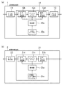
図1は本発明の実施形態に係る送信回路及び受信制御回路の構成を示すブロック図である。送信制御回路1は、FCS生成部11と、その出力側に接続された0挿入部12と、その出力側に接続されたフラグ生成部13とを備えている。受信制御回路2は、0削除及びフラグ検出部21と、その出力側に接続されたエラー検出部22とからなる。
Hereinafter, embodiments of the present invention will be described with reference to the drawings.
FIG. 1 is a block diagram showing a configuration of a transmission circuit and a reception control circuit according to an embodiment of the present invention. The
0挿入部12は、入力キュー記憶部12bと、その出力側に接続されたバッファメモリ12cと、その出力側に接続された出力キュー記憶部12dと、各部を制御する制御部12aと、制御部12aに接続された0挿入テーブル12eとを備えている。また、0削除及びフラグ検出部21は、入力キュー記憶部21bと、その出力側に接続されたバッファメモリ21cと、その出力側に接続された出力キュー記憶部21dと、各部を制御する制御部21aと、制御部21aに接続された0削除及びフラグ検出テーブル21eとを備えている。
The 0
送信制御回路1のFCS生成部11には、図示されていないフレーム生成部で生成されたHDLCフレームデータが入力される。FCS生成部11は、入力されたHDLCフレームデータにFCS(誤り訂正符号)を付加し、0挿入部12へ出力する。0挿入部12では、制御部12aの制御により、入力キュー記憶部12bにデータを記憶すると共に、記憶されたデータを所定ビット単位でバッファメモリ12c に読み込み、0挿入テーブル12eを検索して、0挿入処理を行い、0挿入処理を受けたデータをバッファメモリ12c から出力キュー記憶部12dへ送出する。さらに、出力キュー記憶部12dに記憶されたデータをフラグ生成部13へ送るように制御する。詳細について後述するように、0挿入テーブル12eには、前回入力キュー記憶部12bから読み込まれたビット列と前回出力キュー記憶部12dに送出されたビット列との差異に対応する状態データ、所定ビット数のビット列の並び、出力キュー記憶部12dへ送出されるビット列とそのビット数、及び入力キュー記憶部12bから読み込まれるビット列と出力キュー記憶部12dへ送出されるビット列との差異に対応する次回の状態データの全ての組合せが予め記憶されている。また、入力キュー記憶部12bから読み込まれる所定数のビット列は、その並びに関係なく、入力キュー記憶部12bから削除されるので、0挿入処理の処理回数は入力キュー記憶部12bから読み込まれるビット列の並びとは無関係となる。フラグ生成部12dは、入力されたデータにフラグ01111110を付加し、図示されていないデータ伝送路を介して受信制御回路2へ送信する。
The HDLC frame data generated by a frame generation unit (not shown) is input to the
受信制御回路2の0削除及びフラグ検出部21には、送信制御回路1から送信されたHDLCフレームデータが図示されていないデータ伝送路を介して入力される。0削除及びフラグ検出部21では、制御部21aの制御により、入力キュー記憶部21bにデータを記憶すると共に、記憶されたデータを所定ビット単位でバッファメモリ21cに読み込み、0削除及びフラグ検出テーブル21eを検索して、0削除及びフラグ検出処理を行い、0削除及びフラグ検出処理を受けたデータをバッファメモリ21cから出力キュー記憶部21dへ送出する。さらに、出力キュー記憶部21dに記憶されたデータをエラー検出部22へ送るように制御する。詳細について後述するように、0削除及びフラグ検出テーブル21eには、前回入力キュー記憶部21bから読み込まれたビット列と前回出力キュー記憶部21dに送出されたビット列との差異に対応する状態データ、所定ビット数のビット列の並び、出力キュー記憶部21dへ送出されるビット列とそのビット数、入力キュー記憶部21bから読み込まれるビット列と出力キュー記憶部21dへ送出されるビット列との差異に対応する次回の状態データ、及びデータの種別(通常データ/フラグ/アボート)の全ての組合せが予め記憶されている。また、入力キュー記憶部21bから読み込まれる所定数のビット列は、その並びに関係なく、入力キュー記憶部21bから削除されるので、0削除処理の処理回数は入力キュー記憶部21bから読み込まれるビット列の並びとは無関係となる。エラー検出部22は、入力されたデータのFCSを用いて誤り訂正処理を行い、図示されていないフレーム受信部へ送出する。
The HDLC frame data transmitted from the
以下、図2乃至11を参照しながら、送信制御回路1の0挿入部12の動作を説明する。
まず、0挿入テーブル12eの内容を説明する。本実施形態では、入力キュー記憶部12bから8ビットずつデータがバッファメモリ12cに読み込まれ、0挿入が必要な場合、つまり1が5個続いた場合には0挿入処理を受け、出力キュー記憶部12dへ送出される。また、入力キュー記憶部12bから例えば図28(a)に示した11101111が読み込まれた場合、出力キュー記憶部12dへ送出されるのは図28(c)と同様、1110となり、1111は送出されない。本実施形態では、この1111からなる残りビットを状態番号として保存し、次回に入力キュー記憶部12bから読み込まれる8ビットと同時に扱う。
Hereinafter, the operation of the 0
First, the contents of the 0 insertion table 12e will be described. In this embodiment, when data is read into the
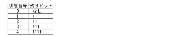
残りビットは、1、11、111及び1111の4種類であるから、図2に示すように、状態番号0乃至4により残りビットの種類を定めている。そして、0挿入テーブル12eには、入力キューから読み込まれる8ビットのビット列の並び、出力キュー記憶部12dへ出力されるビット列とそのビット数、及び状態番号の全ての組合せが予め記憶されている。
Since there are four types of remaining bits, 1, 11, 111, and 1111, the types of remaining bits are determined by
次に、0挿入テーブル12eの作成手順を説明する。
[1]状態番号が0のテーブルの場合
下記(1)〜(4)の手順で作成する。
(1)対象とする8ビットについて、順にビットを調べ、0挿入が必要か否かを判定する。
Next, a procedure for creating the 0 insertion table 12e will be described.
[1] In the case of a table whose status number is 0: Created by the following procedures (1) to (4).
(1) For the 8 bits of interest, the bits are examined in order to determine whether 0 insertion is necessary.
<判定の法則>
・0挿入が必要か否かは1が5個連続しているか、途中で0が出現するかを確認する。
・1の連続数が5個未満の場合、そのまま取り出しビットの並びとすることができる。
・1の連続数が5個に達した場合、続けて0を挿入する事によってそれまで判定したビット列は、取り出しビットの並びとし、1の連続数も0から数え直す。
<Law of judgment>
-Whether or not 0 insertion is necessary is confirmed by checking whether 5 consecutive 1s or 0 appears midway.
-If the number of consecutive 1s is less than 5, the extracted bits can be used as they are.
When the number of consecutive 1s reaches 5, the bit string determined so far by inserting 0s is taken as a sequence of extracted bits, and the number of consecutive 1s is counted again from 0.
(2) (1)の処理を行い、8 ビット全てを調べる。8ビットの終了時点では以下の3つの状態が考えられる。
(ア)8ビット目が0で終了した状態(1の連続数が0)
(イ)8ビット目で1の連続数が5になり、0挿入をした直後の状態(1の連続数が0)
(ウ)8ビット目では1の連続数が1以上5未満であり、次の取り出しビットに影響を与える状態
(2) Perform the process in (1) and check all 8 bits. At the end of 8 bits, the following three states are possible.
(A) State in which the 8th bit ends with 0 (the number of consecutive 1s is 0)
(A) State immediately after the insertion of 0 at the 8th bit when the number of consecutive 1s is 5 (the number of consecutive 1s is 0)
(C) In the 8th bit, the number of consecutive 1s is 1 or more and less than 5 and affects the next extracted bit
(3)(ア)、(イ)の状態の場合、それまで作成した、ビット列、作成済みのビット数がテーブルとなる。また、全てのビットが判定終了したので、残りのビットは0である。これは、残りのビット数が0であるので、次状態が0ということでもある。 (3) In the cases of (a) and (b), the bit string and the number of bits that have been created are used as a table. Since all the bits have been determined, the remaining bits are 0. This also means that the next state is 0 because the remaining number of bits is 0.
(4)(ウ)の状態の場合は、判定済みのビット列とビット列のビット数をテーブルとする。また、終了時点での1の連続数を次の状態番号とする。
残りビット無しの場合 → 次状態:0
残りビット1の場合 → 次状態番号:1
残りビット11の場合 → 次状態番号:2
残りビット111の場合 → 次状態番号:3
残りビット1111の場合 → 次状態番号:4
(4) In the case of (c), the determined bit string and the number of bits of the bit string are used as a table. The number of consecutive 1s at the end time is set as the next state number.
If there are no remaining bits → Next state: 0
If the remaining bit is 1 → Next state number: 1
In case of remaining
In case of remaining
In case of remaining
[2]状態番号が0以外のテーブルの場合
下記(1)〜(5)の手順で作成する。
(1)状態番号により、対象とする8ビットの前に以下のビットを加える。
状態番号:1→1+(対象とする8ビット)
状態番号:2→11+(対象とする8ビット)
状態番号:3→111+(対象とする8ビット)
状態番号:4→1111+(対象とする8ビット)
[2] In the case of a table whose status number is other than 0 Created by the following procedures (1) to (5).
(1) Depending on the state number, the following bits are added before the
Status number: 1 → 1 + (
Status number: 2 → 11 + (
Status number: 3 → 111 + (
Status number: 4 → 1111 + (
(2) (1)で作成したビット列について、順にビットを調べ、0挿入が必要か否かを判定する。
<判定の法則>
・0挿入が必要か否かは1が5個連続しているか、途中で0が出現するかを確認する。
・1の連続数が5個未満の場合、そのまま取り出しビットの並びとすることができる。
・1の連続数が5個に達した場合、続けて0を挿入する事によってそれまで判定したビット列は、取り出しビットの並びとし、1の連続数も0から数え直す。
(2) For the bit string created in (1), the bits are examined in order to determine whether 0 insertion is necessary.
<Law of judgment>
-Whether or not 0 insertion is necessary is confirmed by checking whether 5 consecutive 1s or 0 appears midway.
-If the number of consecutive 1s is less than 5, the extracted bits can be used as they are.
When the number of consecutive 1s reaches 5, the bit string determined so far by inserting 0s is taken as a sequence of extracted bits, and the number of consecutive 1s is counted again from 0.
(3) (2)の処理を行い、(1)で作成したビット全てを調べる。全ビットの終了時点では以下の3つの状態が考えられる。
(ア)最後のビットが0で終了した状態(1の連続数が0)
(イ)最後のビットで1の連続数が5になり、0挿入をした直後の状態(1の連続数が0)
(ウ)最後のビットでは1の連続数が1以上5未満であり、次の取り出しビットに影響を与える状態
(3) The processing of (2) is performed and all the bits created in (1) are examined. At the end of all bits, the following three states are possible.
(A) The state in which the last bit ends with 0 (the number of consecutive 1s is 0)
(A) State immediately after the number of consecutive 1s is 5 in the last bit and 0 is inserted (the number of consecutive 1s is 0)
(C) A state in which the number of consecutive 1s is 1 or more and less than 5 in the last bit and affects the next extracted bit
(4)(ア)、(イ)の状態の場合、それまで作成した、ビット列、作成済みのビット数がテーブルとなる。また、全てのビットが判定終了したので、残りのビットは0である。これは、残りのビット数が0であるので、次状態が0ということでもある。 (4) In the cases of (a) and (b), the bit string and the number of bits already created are tables. Since all the bits have been determined, the remaining bits are 0. This also means that the next state is 0 because the remaining number of bits is 0.
(5)(ウ)の状態の場合は、判定済みのビット列とビット列のビット数をテーブルとする。また、終了時点での1の連続数を次状態番号とする。
残りビット無しの場合 → 次状態番号:0
残りビット1の場合 → 次状態番号:1
残りビット11の場合 → 次状態番号:2
残りビット111の場合 → 次状態番号:3
残りビット1111の場合 → 次状態番号:4
(5) In the case of (c), the determined bit string and the number of bits of the bit string are used as a table. Further, the consecutive number of 1 at the end time is set as the next state number.
If there are no remaining bits → Next state number: 0
If the remaining bit is 1 → Next state number: 1
In case of remaining
In case of remaining
In case of remaining
[3]0挿入テーブルの作成例(状態番号:2、入力ビット列:10111101の変換テーブル作成の場合)
(1)状態2であるから、前回のビット列は11で終了した状態であり、これに10111101を合わせて判定ビット列は1110111101と考えることができる。
(2)(1)で作成したビット列について、0挿入の必要を考慮しながら、取り出しビットを作成すると、111011110+1と分割できる。
(3)よって、取り出しビットは、111011110、ビット数「9」を得る。残りの「1」については次状態に影響を与えるため、今回はデータを確定できず、次の状態を1とする。
(4)以上から、状態番号:2、入力ビット列:10111101の変換テーブルとして、
次状態番号:1 、出力ビット数:9、出力ビット列=111011110
が得られる。
[3] Example of creation of 0 insertion table (when creating a conversion table of status number: 2 and input bit string: 10111101)
(1) Since it is in
(2) For the bit string created in (1), if the extracted bit is created while considering the need for 0 insertion, it can be divided into 1111011110 + 1.
(3) Therefore, 111011110 and the number of bits “9” are obtained as extracted bits. Since the remaining “1” affects the next state, data cannot be determined this time, and the next state is set to 1.
(4) From the above, as a conversion table of state number: 2 and input bit string: 10111101,
Next state number: 1, number of output bits: 9, output bit string = 111011110
Is obtained.
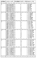
図3は0挿入テーブル12eの一部を抜粋したものである。この図に示されているように、状態番号と入力ビット列が決まれば、それに対応して次状態番号、出力ビット数及び出力ビット列が定まる。なお、入力キュー記憶部12bから最初に読み込まれるビット列の状態番号は0である。
FIG. 3 shows a part of the 0 insertion table 12e. As shown in this figure, when the state number and the input bit string are determined, the next state number, the number of output bits, and the output bit string are determined correspondingly. Note that the state number of the bit string read first from the input
次に図4のフローチャート及び図5乃至11の状態変化を示す図を用いて0挿入方法を説明する。これらの図において、入力キューは入力キュー記憶部12bに記憶されているビット列、出力キューは出力キュー記憶部12dに記憶されているビット列である。なお、この入力キューのビット列の並びは従来例における入力キューのビット列の並びと同じである。
Next, the zero insertion method will be described with reference to the flowchart of FIG. 4 and the diagrams showing the state changes of FIGS. In these figures, the input queue is a bit string stored in the input
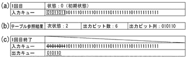
まず、6オクテット(48ビット)入力キューの先頭から1オクテット(8ビット)のデータを選択する(図5(a)、図4のステップS1)。図5(a)において、枠で囲まれた01011011が選択された8ビットを示す。次に、0挿入用テーブルを検索して、(ア)次回の状態番号(次状態番号)、(イ)出力キューに付加するビット数(出力ビット数)、(ウ)及び出力キューに付加するビット列(出力ビット列)を読み出す(図5(b)、ステップS2)。0挿入用テーブルには、入力される8ビットの全ての組み合わせと状態番号数の積(28 ×5=1280通り)に対する上記(ア)、(イ)及び(ウ)のデータが予め格納されている。 First, data of 1 octet (8 bits) is selected from the head of the 6 octet (48 bits) input queue (FIG. 5A, step S1 in FIG. 4). In FIG. 5A, 01011011 surrounded by a frame indicates the selected 8 bits. Next, the 0 insertion table is searched and (a) the next state number (next state number), (b) the number of bits to be added to the output queue (number of output bits), (c) and the number to be added to the output queue. A bit string (output bit string) is read (FIG. 5B, step S2). In the 0 insertion table, the above data (a), (b) and (c) are stored in advance for the product (2 8 × 5 = 1,280) of all 8-bit combinations and the number of state numbers inputted. ing.
ここでは、次状態番号=2、出力ビット数=6、出力ビット列=010110である。なお、入力キューから選択された01011011の状態(初期状態)は0である。ここで、選択された8ビットの全てが出力キューに付加されない理由は、従来例(図27)を参照しなから説明したように、選択された8ビットの末尾の2ビット11は、その2ビットの次に1が3個続いた場合、その次に0挿入処理を行うことになるため、次に選択される先頭の3ビットと併せて処理する必要があり、未確定であるためである。従って、ここでは、出力キューに010110を付加する(ステップS3)。一方、入力キューからは01011011を削除すると共に次状態番号を保存する(ステップS4)。図5(c)において01011011が削除された入力キュー、010110が付加された出力キューを示す。ここで、入力キューの010110に付与された二重線は削除されたビット列を表し、網がけは今回削除されたビット列を表す。また、出力キューに付与された下線は今回付加されたビット列を表す。
Here, the next state number = 2, the number of output bits = 6, and the output bit string = 010110. The state (initial state) of 01011011 selected from the input queue is 0. Here, the reason why all of the selected 8 bits are not added to the output queue is that the last 2
ここで、図5(c)と図27(c)とを比較すると、出力ビット列及び出力ビット数は本実施形態も従来例も同じであるが、削除ビット数は、従来例では出力ビット数と同じであるのに対し、本実施形態では選択されたビット数(=8)と同じになる。そして、本実施形態では、従来例では入力キューから削除せずに残した11を削除し、次状態番号2として保存している。
Here, comparing FIG. 5C and FIG. 27C, the output bit string and the number of output bits are the same in this embodiment and the conventional example, but the number of deleted bits is the same as the number of output bits in the conventional example. In contrast, in the present embodiment, the number of bits (= 8) is the same. In the present embodiment, 11 that remains without being deleted from the input queue in the conventional example is deleted and stored as the
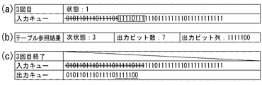
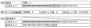
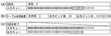
以上のステップS1乃至4を入力キューのビット列がなくなるまで繰り返す(ステップS5)。ここでは、図6(a)に示すように、10111101を選択する。この入力ビット列の状態番号は前回保存された2である。この入力ビット列及び状態番号を用いて0挿入テーブル12eを検索すると、図6(b)に示すように、次状態番号=1、出力ビット数=9、出力ビット列=111011110である。ここで、出力ビット列の先頭の2ビット11は、入力キューから前回選択されて削除されたものの出力ビットにならず、次状態番号により保存されていたものである。次に、111011110を出力キューに付加し(ステップS3)、10111101を入力キューから削除すると共に次状態番号(=1)を保存する(ステップS4)ことで、図6(c)に示す状態となる。
The above steps S1 to S4 are repeated until there is no bit string in the input queue (step S5). Here, 10111101 is selected as shown in FIG. The state number of this input bit string is 2 stored last time. When the 0 insertion table 12e is searched using this input bit string and state number, as shown in FIG. 6B, the next state number = 1, the number of output bits = 9, and the output bit string = 111011110. Here, the first 2
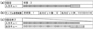
以後、図7乃至10までステップS1乃至4の処理が繰り返し実行され、図11に示す状態になると、ステップS5で”はい”と判定されるので、次のステップS6で状態番号を判断し、その状態番号に対応する数の1を出力キューに付加して1フレームの処理が終わる。図7、8、9及び10では0挿入を行っている。 Thereafter, the processes of steps S1 to S4 are repeatedly executed from FIG. 7 to FIG. 10, and when the state shown in FIG. 11 is reached, “Yes” is determined in step S5. Therefore, the state number is determined in the next step S6. One number corresponding to the state number is added to the output queue, and the processing of one frame is completed. In FIGS. 7, 8, 9 and 10, zero insertion is performed.
このように、本実施形態の0挿入処理では、入力キューから選択した1オクテット(8ビット)を入力ビット列の並びに関係なく全て削除しているため、処理が簡単であり、かつ入力キューのオクテット数と同じ回数のループ処理により完了する。 As described above, in the 0 insertion processing of this embodiment, since 1 octet (8 bits) selected from the input queue is deleted regardless of the arrangement of the input bit string, the processing is simple and the number of octets in the input queue. It is completed by the same number of times of loop processing.
次に、図12乃至24を参照しながら、受送信制御回路2の0削除及びフラグ検出部21の動作を説明する。
Next, the operation of the zero deletion and
まず、0削除及びフラグ検出テーブル21eの内容を説明する。本実施形態では、入力キュー記憶部21bから8ビットずつデータがバッファメモリ21cに読み込まれ、0削除が必要な場合、つまり1が5個続いた場合には0削除処理を受け、出力キュー記憶部21dへ送出される。また、フラグである01111110が読み込まれた場合、フラグ検出処理を行う。ここで、フレームの最初のフラグである開始フラグが検出されたときは、それ以後読み込まれるデータに対して0削除処理を開始し、フレームの最後のフラグである終了フラグが検出されたときは、1フレームの0削除処理を終える。また、0挿入処理と同様、入力キューから選択したビット列の内、出力キューに付加されない残りビット列を識別するために状態番号を保存する。
First, the contents of the 0 deletion and flag detection table 21e will be described. In this embodiment, when data is read into the
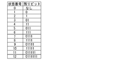
状態番号は、図12に示されているように、状態0から12までの13通りになる。そして、0削除及びフラグ検出テーブル21eには、入力キュー21bから読み込まれる8ビットのビット列の並び、出力キュー記憶部21dへ出力されるビット列とそのビット数、データの種別(通常データ/フラグ/アボート)及び状態番号の全ての組合せが予め記憶されている。
There are 13 state numbers from
次に、0削除及びフラグ検出テーブル21eの作成手順を説明する。
[1]状態0のテーブルの場合
下記(1)〜(5)の手順により作成する。
Next, a procedure for creating the 0 deletion and flag detection table 21e will be described.
[1] In the case of a table in
(1)対象とする8ビットについて、順にビットを調べ、フラグの有無と0削除が必要か否かを判定する。
<判定の法則>
・0挿入が必要か否かは1が5個連続しているか、途中で0が出現するかを確認する。
ただし、フラグの存在も考慮する為、1から始まる1の連続の場合と、0から始まる1の連続は区別する必要がある。
・1から始まる1の連続の場合で、1の連続数が5未満の場合、そのまま取り出しビットの並びとする。
・1から始まる1の連続の場合で、1の連続数が5個で次に続くビットが0の場合、その0を削除したものを取り出しビットの
の並びとする。
・1から始まる1の連続の場合で、1の連続数が6個になる場合、無効なデータであるので, 種別を「無効(アボート)」とする。
・0から始まる1の連続の場合で、1の連続数が5未満の場合、そのまま取り出しビットの並びとする。
・0から始まる1の連続の場合で、1の連続数が5個で次に続くビットが0の場合、その0を削除したものを取り出しビット
の並びとする。
・0から始まる1の連続の場合で、1の連続数が6個で次に続くビットが0の場合、そのビット並びはフラグをあらわすので、
種別を「フラグ」とする。このとき、フラグに該当する01111110の並びは取り出しビットには含めない。
・0から始まる1の連続の場合で、1の連続数が7個になる場合、無効なデータであるので、種別を「無効」とする。
(1) For the 8 bits of interest, the bits are examined in order to determine whether a flag is present and whether 0 deletion is necessary.
<Law of judgment>
-Whether or not 0 insertion is necessary is confirmed by checking whether 5 consecutive 1s or 0 appears midway.
However, in order to consider the presence of the flag, it is necessary to distinguish between the case of 1 starting from 1 and the case of 1 starting from 0.
In the case of 1 continuation starting from 1, if the number of continuations of 1 is less than 5, the extracted bit sequence is used as it is.
If the number of consecutive 1s starts with 1 and the number of consecutive 1s is 5 and the next bit is 0, the one with the 0 removed is taken as a sequence of extracted bits.
-If the number of consecutive 1s starts from 1, and the number of consecutive 1s is 6, it is invalid data, so the type is “invalid (aborted)”.
In the case of 1 consecutive starting from 0, if the number of consecutive 1s is less than 5, the extracted bits are used as they are.
-In the case of a sequence of 1 starting from 0, if the number of consecutive 1s is 5 and the next bit is 0, the one from which the 0 is deleted is taken as an array of bits.
-In the case of 1 consecutive starting from 0, if the number of consecutive 1s is 6 and the next bit is 0, the bit sequence represents a flag.
The type is “flag”. At this time, the sequence of 01111110 corresponding to the flag is not included in the extracted bits.
In the case of 1 continuous starting from 0, if the number of 1 continuous is 7, it is invalid data, so the type is “invalid”.
(2) (1)の処理を行い、8ビット全てを調べる。8ビットの終了時点では以下の4つの状態が考えられる。
(ア)8ビット目が0で終了した場合
(イ)7ビット目まで1が5個連続し、8ビット目の0を削除して終了した場合
(ウ)8ビット目では1の連続数が1以上6未満で有り、次の取り出しビットに処理が依存する場合
(エ)データ種別が「異常」な場合
(2) Perform the process of (1) and check all 8 bits. At the end of 8 bits, the following four states can be considered.
(A) When the 8th bit ends with 0 (b) When 1 ends up to the 7th bit and 1 ends, and the 8th bit deletes 0 (c) When the 8th bit ends with 1 When it is 1 or more and less than 6, and the processing depends on the next fetch bit (D) When the data type is "abnormal"
(3)(ア)、(イ)の状態の場合、データ種別は「通常」、作成済みのビット列とそのビット列のビット数がテーブルになる。また、全てのビットが判定終了したので、残りビットは0である。これは、残りのビット数が0であるので、次状態が0ということである。 (3) In the cases of (a) and (b), the data type is “normal”, and the generated bit string and the number of bits of the bit string are used as a table. Also, since all bits have been determined, the remaining bits are 0. This means that the next state is 0 because the remaining number of bits is 0.
(4)(ウ)の状態の場合は、データ種別は「通常」、作成済みのビット列と、そのビット数がテーブルになる。また、終了時点での確定していないビットの状態により、次状態番号を決める。
残りビットが0の場合→次状態番号:1
残りビットが1の場合→次状態番号:2
残りビットが01の場合→次状態番号:3
残りビットが11の場合→次状態番号:4
残りビットが011の場合→次状態番号:5
残りビットが111の場合→次状態番号:6
残りビットが0111の場合→次状態番号:7
残りビットが1111の場合→次状態番号:8
残りビットが01111の場合→次状態番号:9
残りビットが11111の場合→次状態番号:10
残りビットが011111の場合→次状態番号:11
残りビットが0111111の場合→次状態番号:12
(5)(エ)の状態の場合、データ種別を「異常」とする。
(4) In the case of (c), the data type is “normal”, the created bit string and the number of bits are in a table. Further, the next state number is determined according to the state of the bit which is not fixed at the end time.
If the remaining bits are 0 → Next state number: 1
If the remaining bit is 1, then next state number: 2
If the remaining bits are 01 → Next state number: 3
When the remaining bit is 11, the next state number: 4
If the remaining bits are 011 → next state number: 5
If the remaining bits are 111 → next state number: 6
If the remaining bits are 0111 → next state number: 7
If the remaining bits are 1111 → next state number: 8
If the remaining bits are 01111 → next state number: 9
If the remaining bits are 11111 → next state number: 10
If the remaining bits are 011111 → next state number: 11
If the remaining bits are 0111111 → next state number: 12
(5) In the case of (d), the data type is “abnormal”.
[2]状態番号が0以外のテーブルの場合
下記(1)〜(6)の手順により作成する。
(1)状態により、対象とする8ビットの前に以下のビットを加える。
状態番号:1→0+(対象とする8ビット)
状態番号:2→1+(対象とする8ビット)
状態番号:3→01+(対象とする8ビット)
状態番号:4→11+(対象とする8ビット)
状態番号:5→011+(対象とする8ビット)
状態番号:6→111+(対象とする8ビット)
状態番号:7→0111+(対象とする8ビット)
状態番号:8→1111+(対象とする8ビット)
状態番号:9→01111+(対象とする8ビット)
状態番号:10→11111+(対象とする8ビット)
状態番号:11→011111+(対象とする8ビット)
状態番号:12→0111111+(対象とする8ビット)
[2] In the case of a table whose status number is other than 0 Created by the following procedures (1) to (6).
(1) Depending on the state, the following bits are added before the
Status number: 1 → 0 + (
Status number: 2 → 1 + (
Status number: 3 → 01 + (
Status number: 4 → 11 + (
Status number: 5 → 011 + (
Status number: 6 → 111 + (
Status number: 7 → 0111 + (
Status number: 8 → 1111 + (
Status number: 9 → 01111 + (
Status number: 10 → 11111 + (
Status number: 11 → 011111 + (
Status number: 12 → 0111111 + (
(2) (1)で作成したビット列について、順にビットを調べ、フラグの有無と0削除が必要か否かを判定する。
<判定の法則>
・0挿入が必要か否かは1が5個連続しているか、途中で0が出現するかを確認する。
ただし、フラグの存在も考慮する為、1から始まる1の連続と、0から始まる1の連続とは区別する必要がある。
・1から始まる1の連続の場合で、1の連続数が5未満の場合、そのまま取り出しビットの並びとする。
・1から始まる1の連続の場合で、1の連続数が5個で次に続くビットが0の場合、その0を削除したものを取り出しビットの並びとする。
・1から始まる1の連続の場合で、1の連続数が6個になる場合、無効なデータであるので、種別を「無効」とする。
・0から始まる1の連続の場合で、1の連続数が5未満の場合、そのまま取り出しビットの並びとする。
・0から始まる1の連続の場合で、1の連続数が5個で次に続くビットが0の場合、その0を削除したものを取り出しビット
の並びとする。
・0から始まる1の連続の場合で、1の連続数が6個で次に続くビットが0の場合、そのビット並びはフラグをあらわすので、
種別を「フラグ」とする。このとき、フラグに該当する01111110の並びは取り出しビットには含めない。
・0から始まる1の連続の場合で、1の連続数が7個になる場合、無効なデータであるので、種別を「無効」とする。
(2) For the bit string created in (1), the bits are examined in order to determine whether a flag is present and whether 0 deletion is necessary.
<Law of judgment>
-Whether or not 0 insertion is necessary is confirmed by checking whether 5 consecutive 1s or 0 appears midway.
However, in order to consider the presence of the flag, it is necessary to distinguish between a series of 1 starting from 1 and a series of 1 starting from 0.
In the case of 1 continuation starting from 1, if the number of continuations of 1 is less than 5, the extracted bit sequence is used as it is.
In the case of 1 consecutive starting from 1, if the number of consecutive 1s is 5 and the next bit is 0, the one with the 0 deleted is taken as a sequence of bits.
In the case of 1 continuous starting from 1, if the number of continuous 1 is 6, it is invalid data, so the type is “invalid”.
In the case of 1 consecutive starting from 0, if the number of consecutive 1s is less than 5, the extracted bits are used as they are.
-In the case of a sequence of 1 starting from 0, if the number of consecutive 1s is 5 and the next bit is 0, the one from which the 0 is deleted is taken as an array of bits.
-In the case of 1 consecutive starting from 0, if the number of consecutive 1s is 6 and the next bit is 0, the bit sequence represents a flag.
The type is “flag”. At this time, the sequence of 01111110 corresponding to the flag is not included in the extracted bits.
In the case of 1 continuous starting from 0, if the number of 1 continuous is 7, it is invalid data, so the type is “invalid”.
(3) (2)の処理を行い、(1)で作成したビット全てを調べる。全てのビットの終了時点では以下の4つの状態が考えられる。
(ア)8ビット目が0で終了した場合
(イ)7ビット目まで1が5個連続し、8ビット目の0を削除して終了した場合
(ウ)8ビット目では1の連続数が1以上6未満で有り、次の取り出しビットに処理が依存する場合
(エ)データ種別が「異常」な場合
(3) The processing of (2) is performed and all the bits created in (1) are examined. At the end of all bits, the following four states are possible.
(A) When the 8th bit ends with 0 (b) When 1 ends with 5 consecutive bits up to the 7th bit, and when the 8th bit deletes 0 (c) When the 8th bit ends with 1 When it is 1 or more and less than 6 and processing depends on the next fetch bit (d) When the data type is "abnormal"
(4)(ア)、(イ)の状態の場合、データ種別は「通常」、作成済みのビット列とそのビット列のビット数がテーブルになる。また、全てのビットが判定終了したので、残りビットは0であるこれは、残りのビット数が0であるので、次状態が0ということである。 (4) In the cases of (a) and (b), the data type is “normal”, and the generated bit string and the number of bits of the bit string are used as a table. Since all the bits have been determined, the remaining bits are 0. This means that the next state is 0 because the remaining number of bits is 0.
(5)(ウ)の状態の場合は、データ種別は「通常」、作成済みのビット列と、そのビット数がテーブルになる。また、終了時点での確定していないビットの状態により、次状態番号を決める。
残りビットが0の場合→次状態番号:1
残りビットが1の場合→次状態番号:2
残りビットが01の場合→次状態番号:3
残りビットが11の場合→次状態番号:4
残りビットが011の場合→次状態番号:5
残りビットが111の場合→次状態番号:6
残りビットが0111の場合→次状態番号:7
残りビットが1111の場合→次状態番号:8
残りビットが01111の場合→次状態番号:9
残りビットが11111の場合→次状態番号:10
残りビットが011111の場合→次状態番号:11
残りビットが0111111の場合→次状態番号:12
(6)(エ)の状態の場合、データ種別を「異常」とする。
(5) In the case of (c), the data type is “normal”, the created bit string and the number of bits are in a table. Further, the next state number is determined according to the state of the bit which is not fixed at the end time.
If the remaining bits are 0 → Next state number: 1
If the remaining bit is 1, then next state number: 2
If the remaining bits are 01 → Next state number: 3
When the remaining bit is 11, the next state number: 4
If the remaining bits are 011 → next state number: 5
If the remaining bits are 111 → next state number: 6
If the remaining bits are 0111 → next state number: 7
If the remaining bits are 1111 → next state number: 8
If the remaining bits are 01111 → next state number: 9
If the remaining bits are 11111 → next state number: 10
If the remaining bits are 011111 → next state number: 11
If the remaining bits are 0111111 → next state number: 12
(6) In the case of (d), the data type is “abnormal”.
[3]0削除テーブルの作成例(状態番号:12、入力ビット列:00101101の変換テーブルの作成の場合)
(1)状態番号:12であるから、前回のビット列は0111111で終了した状態であり、これに今回の00101101を合わせて判定ビット列は011111100101101と考えることができる。
(2) (1)で作成したビット列について、フラグの存在と0削除の必要を考慮しながら、取り出しビットを作成すると、01111110+01011+01に分割できる。よって、ひとつ目の01111110から種別はフラグ、取り出しビットは01011、ビット数5を得る。
残りの01については次状態に影響を与えるため、今回はデータを確定できず、次状態番号を3とする。
以上から、状態番号:12、入力ビット列:00101101」の変換テーブルとして、
次状態番号:3、出力ビット数:5、出力ビット列=111011110
が得られる。
[3] Example of creating a 0 deletion table (in the case of creating a conversion table of state number: 12, input bit string: 00101101)
(1) Since the state number is 12, the previous bit string ends in 0111111. With this addition of 00101101 to this, the determination bit string can be considered as 011111100101101.
(2) With regard to the bit string created in (1), when taking out bits are created while considering the presence of the flag and the need for 0 deletion, it can be divided into 01111110 + 01011 + 01. Therefore, from the first 01111110, the type is a flag, the extraction bit is 01011, and the number of bits is 5.
Since the remaining 01 affects the next state, data cannot be determined this time, and the next state number is set to 3.
From the above, as a conversion table of state number: 12, input bit string: 00101101,
Next state number: 3, number of output bits: 5, output bit string = 111111110
Is obtained.
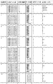
図13は0削除及びフラグ検出テーブル21eの一部を抜粋したものである。この図に示されているように、状態番号と入力ビット列が決まれば、それに対応してデータ種別が判定されると共に次状態番号、出力ビット数及び出力ビット列が定まる。なお、入力キュー記憶部12bから最初に読み込まれるビット列の状態番号は0である。
FIG. 13 shows a part of the 0 deletion and flag detection table 21e. As shown in this figure, when the state number and the input bit string are determined, the data type is determined correspondingly, and the next state number, the number of output bits, and the output bit string are determined. Note that the state number of the bit string read first from the input
次に、図14及び15のフローチャート並びに図16乃至24の状態変化を示す図を用いて0削除及びフラグ検出方法を説明する。これらの図において、入力キューはこれから0削除及びフラグ検出処理を受けるデータ、出力キューは0削除及びフラグ検出処理を受けたデータである。また、図14は開始フラグ検出処理であり、図15は開始フラグ検出後の処理である。なお、この入力キューのビット列の並びは従来例における入力キューのビット列の並びと同じである。 Next, the zero deletion and flag detection method will be described using the flowcharts of FIGS. 14 and 15 and the diagrams showing the state changes of FIGS. In these figures, an input queue is data that will be subjected to 0 deletion and flag detection processing, and an output queue is data that has been subjected to 0 deletion and flag detection processing. FIG. 14 shows the start flag detection process, and FIG. 15 shows the process after the start flag is detected. Note that the bit sequence of the input queue is the same as the bit sequence of the input queue in the conventional example.
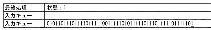
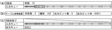
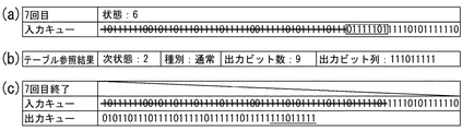
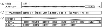
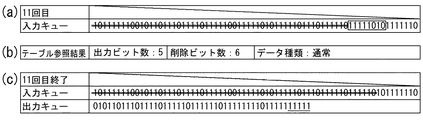
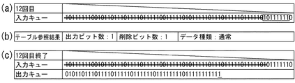
まず、0削除の前にフラグ検出を行うために、入力キューの先頭から1オクテット(8ビット)のデータを選択する(図16(a)、図14のステップS11)。図16(a)において、枠で囲まれた10111111が選択された8ビットを示す。次に、0削除及びフラグ検出テーブル21eを検索して、(ア)次状態番号、(イ)データ種別(通常データ/フラグ/アボート)、(ウ)出力キューに付加するビット数(出力ビット数)、及び(エ)出力キューに付加するビット列(出力ビット列)を読み出す。(図16(b)、ステップS12)。ここでは、次状態番号=12、データ種別=通常、出力ビット数=1、出力ビット列=1である。従って、フラグではないから、ステップS13で”いいえ”と判断し、ステップS14で入力キューから8ビットを削除すると共に状態番号12を保存した後にステップS11に戻る。フラグが検出される迄は出力キューにデータは付加されないので、図16(c)に示すように、10111111が入力キューから削除され、出力キューに付加されるデータはない。
First, in order to detect a flag before deleting 0, data of 1 octet (8 bits) is selected from the head of the input queue (FIG. 16A, step S11 in FIG. 14). In FIG. 16A, 10111111 surrounded by a frame indicates 8 bits selected. Next, the 0 deletion and flag detection table 21e is searched, and (a) the next state number, (b) the data type (normal data / flag / abort), and (c) the number of bits to be added to the output queue (number of output bits). And (d) reading out a bit string (output bit string) to be added to the output queue. (FIG. 16B, step S12). Here, the next state number = 12, the data type = normal, the number of output bits = 1, and the output bit string = 1. Therefore, since it is not a flag, it is determined as “No” in Step S13, and 8 bits are deleted from the input queue in Step S14 and the
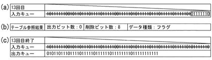
再び入力キューから8ビットを選択する(ステップS11)。今回は00101101が選択されている(図17(a))。この入力ビット列の状態番号は前回保存された12である。この入力ビット列及び状態番号を用いて0削除及びフラグ検出テーブル21eを検索すると(ステップS12)、次状態番号=3、データ種別=フラグ、出力ビット数=5、出力ビット列=01011である(図17(b))。フラグが検出されているから、ステップS13で”はい”と判断し、ステップS15で出力キューに出力ビット列を付加した後、ステップS16で00101101を削除すると共に状態番号3を保存し、開始フラグ検出処理を終える。
Again, 8 bits are selected from the input queue (step S11). This time, 00101101 is selected (FIG. 17A). The state number of this input bit string is 12 stored last time. When the 0 deletion and flag detection table 21e is searched using this input bit string and state number (step S12), next state number = 3, data type = flag, number of output bits = 5, and output bit string = 01011 (FIG. 17). (B)). Since the flag is detected, it is determined as “Yes” in Step S13, and after adding the output bit string to the output queue in Step S15, 00101101 is deleted and the
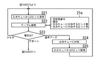
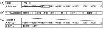
開始フラグが検出されたので、次に図15に示されている0削除処理を実行する。入力キューの先頭から1オクテット(8ビット)のデータを選択する(図18(a)、図15のステップS21)。ここでは、11011110が選択されている。次に、0削除及びフラグ検出テーブル21eを検索すると(ステップS22)、次状態番号=1、データ種別=通常、出力ビット数=9、出力ビット列=011101111である(図18(b))。従って、ステップS23通常データと判定し、ステップS24で011101111を出力キューに付加し、ステップS25で入力キューから11011110を削除すると共に状態番号1を保存する(図18(c))。
Since the start flag is detected, the zero deletion process shown in FIG. 15 is executed next. Data of 1 octet (8 bits) is selected from the head of the input queue (FIG. 18A, step S21 in FIG. 15). Here, 11011110 is selected. Next, when the 0 deletion and flag detection table 21e is searched (step S22), the next state number = 1, the data type = normal, the number of output bits = 9, and the output bit string = 0111101111 (FIG. 18B). Accordingly, step S23 is determined to be normal data, and 011101111 is added to the output queue in step S24, and 11011110 is deleted from the input queue in step S25, and
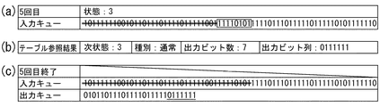
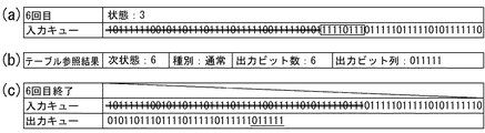
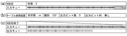
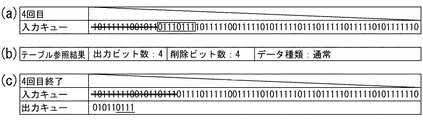
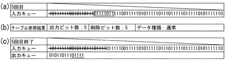
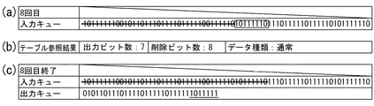
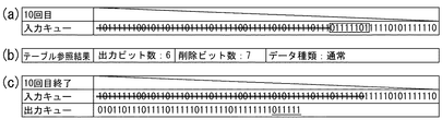
以後、図19乃至図24迄ステップS21乃至25の処理が繰り返し実行され、図24に示すようにステップS23でフラグが検出され、1フレームの処理が終わる。図19、20、21、22、及び24では0削除が行われている。1フレームの処理が終わると、ステップS21に戻って次のフレームの処理を行う。また、ステップS23でアボートが検出された場合は、図14のステップS11に戻ってフラグ検出処理を行う。 Thereafter, the processing of steps S21 to S25 is repeatedly executed from FIG. 19 to FIG. 24, and the flag is detected at step S23 as shown in FIG. In FIG. 19, 20, 21, 22, and 24, 0 deletion is performed. When the processing for one frame is completed, the process returns to step S21 to process the next frame. If an abort is detected in step S23, the process returns to step S11 in FIG. 14 to perform flag detection processing.
このように、本実施形態の0削除処理では、入力キューから選択した1オクテット(8ビット)を入力ビット列の並びに関係なく全て削除しているため、処理が簡単であり、かつ入力キューのオクテット数と同じ回数のループ処理により完了する。 As described above, in the 0 deletion process of the present embodiment, all the 1 octets (8 bits) selected from the input queue are deleted regardless of the arrangement of the input bit strings, so that the process is simple and the number of octets in the input queue. It is completed by the same number of times of loop processing.
なお、以上の説明では、最適値の8ビット単位で入力キューからビット列を読み込むものとしたが、8ビット以外のビット数単位で読み込むようにしてもよい。また、本発明は、HDLC手順だけでなく、ビット列の並びを特定の規則に従って変換する処理であり、かつ変換の前後にビット数が増減する処理に対しても同様に適用できる。 In the above description, the bit string is read from the input queue in units of 8 bits of the optimum value, but may be read in units of bits other than 8 bits. Further, the present invention is not only the HDLC procedure but also a process for converting the sequence of bit strings according to a specific rule, and can be similarly applied to a process for increasing or decreasing the number of bits before and after the conversion.
12・・・0挿入回路、12a,21a・・・制御部、12b,21b・・・入力キュー記憶部、12d,21d・・・出力キュー記憶部、12e・・・0挿入テーブル、21・・・0削除及びフラグ検出部、21e・・・0削除及びフラグ検出テーブル。 12 ... 0 insertion circuit, 12a, 21a ... control unit, 12b, 21b ... input queue storage unit, 12d, 21d ... output queue storage unit, 12e ... 0 insertion table, 21 ... 0 deletion and flag detection unit, 21e... 0 deletion and flag detection table.
Claims (4)
Priority Applications (1)
| Application Number | Priority Date | Filing Date | Title |
|---|---|---|---|
| JP2004107597A JP4314479B2 (en) | 2004-03-31 | 2004-03-31 | Data processing apparatus and program |
Applications Claiming Priority (1)
| Application Number | Priority Date | Filing Date | Title |
|---|---|---|---|
| JP2004107597A JP4314479B2 (en) | 2004-03-31 | 2004-03-31 | Data processing apparatus and program |
Publications (2)
| Publication Number | Publication Date |
|---|---|
| JP2005295216A true JP2005295216A (en) | 2005-10-20 |
| JP4314479B2 JP4314479B2 (en) | 2009-08-19 |
Family
ID=35327659
Family Applications (1)
| Application Number | Title | Priority Date | Filing Date |
|---|---|---|---|
| JP2004107597A Expired - Fee Related JP4314479B2 (en) | 2004-03-31 | 2004-03-31 | Data processing apparatus and program |
Country Status (1)
| Country | Link |
|---|---|
| JP (1) | JP4314479B2 (en) |
Cited By (2)
| Publication number | Priority date | Publication date | Assignee | Title |
|---|---|---|---|---|
| JP2009021941A (en) * | 2007-07-13 | 2009-01-29 | Rohm Co Ltd | Information communication terminal, radio communication device, and radio communication network |
| US8347160B2 (en) | 2007-07-13 | 2013-01-01 | Rohm Co., Ltd. | Information communication terminal, radio communication apparatus and radio communication network system capable of performing communication corresponding to purpose |
-
2004
- 2004-03-31 JP JP2004107597A patent/JP4314479B2/en not_active Expired - Fee Related
Cited By (2)
| Publication number | Priority date | Publication date | Assignee | Title |
|---|---|---|---|---|
| JP2009021941A (en) * | 2007-07-13 | 2009-01-29 | Rohm Co Ltd | Information communication terminal, radio communication device, and radio communication network |
| US8347160B2 (en) | 2007-07-13 | 2013-01-01 | Rohm Co., Ltd. | Information communication terminal, radio communication apparatus and radio communication network system capable of performing communication corresponding to purpose |
Also Published As
| Publication number | Publication date |
|---|---|
| JP4314479B2 (en) | 2009-08-19 |
Similar Documents
| Publication | Publication Date | Title |
|---|---|---|
| US8200646B2 (en) | Efficient retrieval of variable-length character string data | |
| US8532988B2 (en) | Searching for symbol string | |
| US8542137B2 (en) | Decoding encoded data | |
| CA2275391C (en) | File processing method, data processing device, and storage medium | |
| JP4314479B2 (en) | Data processing apparatus and program | |
| US6433709B1 (en) | Decoding method and decoding apparatus for variable length code words, and computer readable recording medium for storing decoding program for variable length code words | |
| JP4356495B2 (en) | Data processing apparatus and program | |
| JP4314478B2 (en) | Data processing apparatus and program | |
| JP3725443B2 (en) | Method and system for converting Unicode text to a mixed code page | |
| JP5428316B2 (en) | Identifier shortening display program, identifier shortening display device, and identifier shortening display method | |
| CN117709298B (en) | Double character stream scanning method, electronic equipment, storage medium and system | |
| JP2005130490A (en) | Decryption of false synchronous code protection (FSP) by software | |
| JPH09246988A (en) | Decoding device and method | |
| CN114329105B (en) | Character string detection method and device | |
| JPH09246989A (en) | Decoding device and method | |
| JP2023143001A (en) | Information processing device and program | |
| JP4329493B2 (en) | Dictionary data compression apparatus, electronic dictionary apparatus, and program | |
| US6954155B2 (en) | Data compression method and processor | |
| JP4061283B2 (en) | Apparatus, method and program for converting lexical data to data | |
| JP2918380B2 (en) | Post-processing method of character recognition result | |
| JP2006031331A (en) | Program conversion execution computer, program conversion execution method, and program | |
| JPS6028371A (en) | Data storage system | |
| JP2003152549A (en) | Decoding method, decoding device, computer program, and recording medium | |
| CN118713794A (en) | Scrambling and descrambling method, device, equipment and chip | |
| JP2005275880A (en) | Device, method and program for converting word and phrase into data |
Legal Events
| Date | Code | Title | Description |
|---|---|---|---|
| RD04 | Notification of resignation of power of attorney |
Free format text: JAPANESE INTERMEDIATE CODE: A7424 Effective date: 20051031 |
|
| A621 | Written request for application examination |
Free format text: JAPANESE INTERMEDIATE CODE: A621 Effective date: 20061030 |
|
| A977 | Report on retrieval |
Free format text: JAPANESE INTERMEDIATE CODE: A971007 Effective date: 20090416 |
|
| TRDD | Decision of grant or rejection written | ||
| A01 | Written decision to grant a patent or to grant a registration (utility model) |
Free format text: JAPANESE INTERMEDIATE CODE: A01 Effective date: 20090422 |
|
| A01 | Written decision to grant a patent or to grant a registration (utility model) |
Free format text: JAPANESE INTERMEDIATE CODE: A01 |
|
| A61 | First payment of annual fees (during grant procedure) |
Free format text: JAPANESE INTERMEDIATE CODE: A61 Effective date: 20090505 |
|
| R150 | Certificate of patent or registration of utility model |
Ref document number: 4314479 Country of ref document: JP Free format text: JAPANESE INTERMEDIATE CODE: R150 Free format text: JAPANESE INTERMEDIATE CODE: R150 |
|
| FPAY | Renewal fee payment (event date is renewal date of database) |
Free format text: PAYMENT UNTIL: 20120529 Year of fee payment: 3 |
|
| FPAY | Renewal fee payment (event date is renewal date of database) |
Free format text: PAYMENT UNTIL: 20120529 Year of fee payment: 3 |
|
| FPAY | Renewal fee payment (event date is renewal date of database) |
Free format text: PAYMENT UNTIL: 20130529 Year of fee payment: 4 |
|
| FPAY | Renewal fee payment (event date is renewal date of database) |
Free format text: PAYMENT UNTIL: 20130529 Year of fee payment: 4 |
|
| LAPS | Cancellation because of no payment of annual fees |