JP2005295071A - Data receiver - Google Patents
Data receiver Download PDFInfo
- Publication number
- JP2005295071A JP2005295071A JP2004105339A JP2004105339A JP2005295071A JP 2005295071 A JP2005295071 A JP 2005295071A JP 2004105339 A JP2004105339 A JP 2004105339A JP 2004105339 A JP2004105339 A JP 2004105339A JP 2005295071 A JP2005295071 A JP 2005295071A
- Authority
- JP
- Japan
- Prior art keywords
- clock
- vcxo
- reference clock
- vco
- digital data
- Prior art date
- Legal status (The legal status is an assumption and is not a legal conclusion. Google has not performed a legal analysis and makes no representation as to the accuracy of the status listed.)
- Withdrawn
Links
- 230000010355 oscillation Effects 0.000 claims abstract description 33
- 230000005540 biological transmission Effects 0.000 claims description 33
- 230000001360 synchronised effect Effects 0.000 claims description 23
- 239000013078 crystal Substances 0.000 abstract description 4
- 238000000034 method Methods 0.000 description 11
- 238000005070 sampling Methods 0.000 description 8
- 230000003321 amplification Effects 0.000 description 5
- 238000003199 nucleic acid amplification method Methods 0.000 description 5
- 238000006243 chemical reaction Methods 0.000 description 2
- 230000006866 deterioration Effects 0.000 description 2
- 230000003287 optical effect Effects 0.000 description 2
- 230000008929 regeneration Effects 0.000 description 2
- 238000011069 regeneration method Methods 0.000 description 2
- 238000001514 detection method Methods 0.000 description 1
- 238000010586 diagram Methods 0.000 description 1
- 238000011084 recovery Methods 0.000 description 1
Images
Landscapes
- Signal Processing For Digital Recording And Reproducing (AREA)
- Synchronisation In Digital Transmission Systems (AREA)
Abstract
Description
本発明は、データ送信装置からデジタルインターフェースを介して送信されたデジタルデータを受信するデータ受信装置に関する。 The present invention relates to a data receiving apparatus that receives digital data transmitted from a data transmitting apparatus via a digital interface.
デジタル・バーサタイル・ディスクなどの光ディスクを再生し、光ディスクに記録されているデジタルデータ(ビデオデータ、オーディオデータ等)を出力する再生装置と、再生装置から出力されたデジタルデータを受信し、当該デジタルデータのうちオーディオデータを増幅してスピーカに出力し、また、ビデオデータをモニタに出力する増幅装置がある。近年、この再生装置と増幅装置との間のオーディオデータの伝送に、IEEE(Institute of Electrical and Electronic Engineers)1394インターフェースなどのデジタルインターフェースが用いられ始めている。 A playback device that plays back an optical disc such as a digital versatile disc and outputs digital data (video data, audio data, etc.) recorded on the optical disc, receives the digital data output from the playback device, and receives the digital data Among them, there is an amplifying apparatus that amplifies audio data and outputs it to a speaker, and outputs video data to a monitor. In recent years, digital interfaces such as an IEEE (Institute of Electrical and Electronic Engineers) 1394 interface have begun to be used for transmission of audio data between the reproduction apparatus and the amplification apparatus.
デジタルインターフェースを用いて再生装置と増幅装置との間でオーディオデータの伝送を行う場合、データ送信側の再生装置は、オーディオデータを再生装置内部で生成するマスタークロックに基づいて符号化して送信し、データ受信側の増幅装置は、受信したオーディオデータを増幅装置内部で生成するマスタークロックに基づいてデジタル信号処理やデジタルアナログ変換の処理を行う。 When audio data is transmitted between a playback device and an amplification device using a digital interface, the playback device on the data transmission side encodes and transmits audio data based on a master clock generated inside the playback device, The amplifying device on the data receiving side performs digital signal processing and digital / analog conversion processing based on a master clock that generates received audio data inside the amplifying device.
このようなシステムにおいて、再生装置と増幅装置は、マスタークロックを生成するクロック生成手段をそれぞれ独立して備えているため、増幅装置のクロック生成手段が生成したマスタークロックが再生装置のクロック生成手段が生成したマスタークロックに同期してない場合、再生装置から受信したオーディオデータを増幅装置側が正常に復元できず、オーディオデータを再生した際にノイズが発生したり、オーディオデータが途切れたりすることがある。このため、受信側の装置(増幅装置)では、PLL(Phase Locked Loop)回路などにより、送信側の装置(再生装置)から送信されてきたデジタルデータに含まれるクロックに受信側の装置のマスタークロックを同期させる回路を備えている。 In such a system, since the reproduction device and the amplification device are each independently provided with clock generation means for generating a master clock, the master clock generated by the clock generation means of the amplification device is replaced by the clock generation means of the reproduction device. If it is not synchronized with the generated master clock, the amplifying device cannot correctly restore the audio data received from the playback device, and noise may be generated or the audio data may be interrupted when the audio data is played back. . Therefore, in the receiving device (amplifying device), the master clock of the receiving device is added to the clock included in the digital data transmitted from the transmitting device (reproducing device) by a PLL (Phase Locked Loop) circuit or the like. Is provided.
このようなPLL回路には、一般には、電圧制御発振器(Voltage Controlled Oscillator:VCO)、または、電圧制御型水晶発振器(Voltage Controlled Xtal Oscillator:VCXO)が用いられる。VCOは、クロック同期の許容範囲がクロックの中心周波数に対し±1000ppm(Parts Per Million)と広いが、生成されたマスタークロックに含まれるジッターが多くオーディオデータの音質劣化の原因となる。一方、VCXOは、生成されたマスタークロックに含まれるジッターが少なくオーディオデータを高音質に再生することができるが、クロック同期の許容範囲がクロックの中心周波数に対し±50ppmと狭く、クロックの同期が外れやすい。 Generally, a voltage controlled oscillator (Voltage Controlled Oscillator: VCO) or a voltage controlled crystal oscillator (Voltage Controlled Xtal Oscillator: VCXO) is used for such a PLL circuit. The VCO has a wide clock synchronization tolerance range of ± 1000 ppm (Parts Per Million) with respect to the center frequency of the clock. However, the generated master clock has a large amount of jitter, which causes deterioration of the sound quality of audio data. On the other hand, VCXO has low jitter contained in the generated master clock and can reproduce audio data with high sound quality, but the allowable range of clock synchronization is as narrow as ± 50 ppm with respect to the center frequency of the clock, and the clock synchronization is Easy to come off.
特許文献1には、PLL回路にVCOを使用し、VCOのレンジ抵抗を変更することによって、高い発振安定性が得られるPLL回路が開示されている。また、特許文献2には、VCXOの出力クロックと分周回路から得られる音声クロックとを位相比較し、その位相誤差に基づいてVCOの発振周波数を制御し、VCOから出力されるクロックを音声クロックとして、受信側で復元する音声クロックの周波数数及び位相を送信側の音声クロックの周波数及び位相に精度よく一致させる音声クロック復元装置が開示されている。
Patent Document 1 discloses a PLL circuit that obtains high oscillation stability by using a VCO in the PLL circuit and changing the range resistance of the VCO. In
特許文献1に開示されているPLL回路は、VCOを用いて安定してクロックを発振させることができるが、当該PLL回路で発生したクロックに基づいてオーディオデータを復元した場合に、VCOのクロックに含まれるジッターによりオーディオデータの音質が劣化することがある。 The PLL circuit disclosed in Patent Document 1 can stably oscillate a clock using a VCO. However, when audio data is restored based on the clock generated by the PLL circuit, the PLL circuit uses the VCO clock. The sound quality of the audio data may be deteriorated due to the included jitter.
特許文献2に開示されている音声クロック復元装置は、VCOから高精度のクロックを出力させることができるが、クロックの発振源としてVCXOを使用しているため、クロック同期の許容範囲が狭く、送信側装置から送信されてきたオーディオデータのクロック周波数が当該音声クロック復元装置のクロック周波数と著しくずれている場合、クロックが同期せず、正常にオーディオデータを復元できなくなり、音途切れ或いはノイズが発生する場合がある。
The audio clock recovery device disclosed in
また、特許文献1に開示されているVCOと特許文献2に開示されているVCXOの両方を用い、これらを切り換えてデータ送信装置から送信されたデジタルデータのクロックに同期させることが考えられるが、基準クロックの切り換え時にオーディオデータの音途切れが発生したりノイズが発生することがある。
In addition, it is conceivable to use both the VCO disclosed in Patent Document 1 and the VCXO disclosed in
本発明は、データ送信装置から送信されてくるデジタルデータのクロック周波数に対応して当該クロックに同期したマスタークロックをVCOとVCXOを用いて生成し、オーディオデータを音質良く、また、音途切れやノイズが発生することなく再生させることができるデータ受信装置を提供することを目的とする。 The present invention uses a VCO and a VCXO to generate a master clock synchronized with the clock corresponding to the clock frequency of the digital data transmitted from the data transmission device, thereby making audio data good in sound quality, and sound interruptions and noise. It is an object of the present invention to provide a data receiving apparatus that can be played back without occurrence of the error.
本願の発明は、データ受信装置において、データ送信装置から送信されたデジタルデータを受信するデジタルデータ受信部と、VCXO基準クロックを発振するVCXOクロック発振部と、VCO基準クロックを発振するVCOクロック発振部と、前記VCXO基準クロック又は前記VCO基準クロックを用いて前記受信したデジタルデータのクロックに同期するマスタークロックを生成するマスタークロック生成部と、前記マスタークロックに基づいて動作し前記受信したデジタルデータに含まれるオーディオデータに対して信号処理を施し出力する信号処理部と、前記受信したデジタルデータのクロック周波数と前記VCXO基準クロックからVCO基準クロックに切り換える周波数の範囲を示す第1切換閾値とを比較し、前記受信したデジタルデータのクロック周波数に基づいて前記前記VCXO基準クロックが前記第1切換閾値内の場合には前記マスタークロック生成部に前記VCXO基準クロックを用いてマスタークロックを生成させ、前記受信したデジタルデータのクロック周波数に基づいて前記VCXO基準クロックが前記第1切換閾値の範囲を外れた場合には前記マスタークロック生成部に前記VCO基準クロックを用いてマスタークロックを生成させる制御を行う制御部とを備えることを特徴とする。 The present invention relates to a data receiving device, a digital data receiving unit for receiving digital data transmitted from the data transmitting device, a VCXO clock oscillating unit for oscillating a VCXO reference clock, and a VCO clock oscillating unit for oscillating a VCO reference clock. A master clock generation unit that generates a master clock synchronized with the clock of the received digital data using the VCXO reference clock or the VCO reference clock, and operates based on the master clock and is included in the received digital data A signal processing unit that performs signal processing on the audio data to be output, and compares a clock frequency of the received digital data with a first switching threshold that indicates a frequency range for switching from the VCXO reference clock to the VCO reference clock, Received When the VCXO reference clock is within the first switching threshold based on the clock frequency of digital data, the master clock generation unit generates a master clock using the VCXO reference clock, and the received clock of the digital data A control unit that controls the master clock generation unit to generate a master clock using the VCO reference clock when the VCXO reference clock is out of the first switching threshold range based on a frequency. Features.
本願の発明は、データ受信装置において、データ送信装置から送信されたデジタルデータを受信するデジタルデータ受信部と、VCXO基準クロックを発振するVCXOクロック発振部と、VCO基準クロックを発振するVCOクロック発振部と、前記VCXO基準クロック又は前記VCO基準クロックを用いて前記受信したデジタルデータのクロックに同期するマスタークロックを生成するマスタークロック生成部と、前記マスタークロックに基づいて動作し前記受信したデジタルデータに含まれるオーディオデータに対して信号処理を施し出力する信号処理部と、前記受信したデジタルデータのクロック周波数と前記VCXO基準クロックからVCO基準クロックに切り換える周波数の範囲を示す第1切換閾値とを比較し、前記受信したデジタルデータのクロック周波数に基づいて前記VCXO基準クロックが前記第1切換閾値の範囲を外れ前記マスタークロック生成部に前記VCO基準クロックを用いてマスタークロックを生成させた後、当該デジタルデータを送信したデータ送信装置から送信されたオーディオデータの再生が予め定めた条件を満たした場合に当該データ送信装置に対応する基準クロックとして前記VCXO基準クロックを設定する制御を行う制御部とを備えることを特徴とする。 The present invention relates to a data receiving device, a digital data receiving unit for receiving digital data transmitted from the data transmitting device, a VCXO clock oscillating unit for oscillating a VCXO reference clock, and a VCO clock oscillating unit for oscillating a VCO reference clock. A master clock generation unit that generates a master clock synchronized with the clock of the received digital data using the VCXO reference clock or the VCO reference clock, and operates based on the master clock and is included in the received digital data A signal processing unit that performs signal processing on the audio data to be output, and compares a clock frequency of the received digital data with a first switching threshold that indicates a frequency range for switching from the VCXO reference clock to the VCO reference clock, Received Data obtained by transmitting the digital data after the VCXO reference clock is out of the first switching threshold range based on the clock frequency of the digital data and causing the master clock generation unit to generate the master clock using the VCO reference clock. And a control unit that performs control to set the VCXO reference clock as a reference clock corresponding to the data transmission apparatus when reproduction of audio data transmitted from the transmission apparatus satisfies a predetermined condition. .
本願の発明は、前述したデータ受信装置において、前記制御部は、オーディオデータの再生中に前記受信したデジタルデータのクロック周波数に基づいて前記VCXO基準クロックを監視し、当該VCXO基準クロック周波数が前記第1切換閾値の範囲を外れた場合、オーディオデータの微小レベル期間を検出した時又はオーディオデータのトラックが変わった時に前記マスタークロック生成部を制御しマスタークロックの生成に用いる基準クロックを前記VCXO基準クロックから前記VCO基準クロックに切り換えることを特徴とする。 According to the present invention, in the data receiving apparatus described above, the control unit monitors the VCXO reference clock based on a clock frequency of the received digital data during reproduction of audio data, and the VCXO reference clock frequency is When the switching threshold value is out of range, the master clock generation unit is controlled when the minute level period of the audio data is detected or the track of the audio data is changed, and the reference clock used for generating the master clock is the VCXO reference clock. To the VCO reference clock.
本願の発明は、前述したデータ受信装置において、前記制御部は、オーディオデータの再生中に前記受信したデジタルデータのクロック周波数に基づいて前記VCXO基準クロックを監視し、当該VCXO基準クロック周波数が前記第1切換閾値の範囲を外れ、前記VCXOクロック発振部が発振可能なクロックの周波数の許容範囲を示す第2切換閾値の範囲を外れた場合、前記マスタークロック生成部を制御しマスタークロックの生成に用いる基準クロックを前記VCXO基準クロックから前記VCO基準クロックに切り換えることを特徴とする。 According to the present invention, in the data receiving apparatus described above, the control unit monitors the VCXO reference clock based on a clock frequency of the received digital data during reproduction of audio data, and the VCXO reference clock frequency is When outside the range of one switching threshold and outside the range of the second switching threshold indicating the allowable frequency range of the clock that the VCXO clock oscillation unit can oscillate, the master clock generation unit is controlled and used to generate a master clock. The reference clock is switched from the VCXO reference clock to the VCO reference clock.
本発明によれば、データ受信装置において、データ送信装置から送信されてくるデジタルデータのクロック周波数に対応して当該クロックに同期したマスタークロックをVCOとVCXOを用いて生成し、オーディオデータを音質良く、また、音途切れやノイズが発生することなく再生させることができる。 According to the present invention, in the data receiving apparatus, a master clock synchronized with the clock corresponding to the clock frequency of the digital data transmitted from the data transmitting apparatus is generated using the VCO and the VCXO, and the audio data is improved in sound quality. Also, it can be played back without sound interruption or noise.
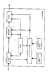
図1は、本発明のデータ受信装置の一実施例の構成を示す図である。
図1において、データ受信装置は、デジタルデータ受信部1、信号処理部2、出力部3、VCXOクロック発振部4、VCOクロック発振部5、マスタークロック生成部6、制御部7を備える。
FIG. 1 is a diagram showing a configuration of an embodiment of a data receiving apparatus of the present invention.
1, the data receiving apparatus includes a digital data receiving unit 1, a
デジタルデータ受信部1は、例えば、IEEE1394インターフェース等のデジタルインターフェースであり、データ送信装置から送信されてきたデジタルデータを受信し、受信したデジタルデータを信号処理部2、マスタークロック生成部6及び制御部7に出力する。
The digital data receiving unit 1 is, for example, a digital interface such as an IEEE 1394 interface, receives digital data transmitted from a data transmission device, and receives the received digital data as a
データ送信装置は、データ送信装置が備えるマスタークロック生成部により生成されたマスタークロックに基づいて、オーディオデータをデジタルインターフェースに適合したフォーマットのデジタルデータに変換し、デジタルインターフェースを介してデータ受信装置に送信する。また、データ送信装置は、オーディオデータと共に、データ送信装置に固有に割り当てられているGUID(General Unique IDentification)等のID(IDentification)情報もデジタルデータとして送信する。データ受信装置は、デジタルデータに含まれるID情報により、データ送信装置を識別することができる。 The data transmission device converts audio data into digital data in a format suitable for the digital interface based on the master clock generated by the master clock generation unit included in the data transmission device, and transmits the digital data to the data reception device via the digital interface. To do. The data transmission apparatus also transmits ID (IDentification) information such as GUID (General Unique IDentification) uniquely assigned to the data transmission apparatus as digital data together with the audio data. The data receiving device can identify the data transmitting device based on the ID information included in the digital data.
信号処理部2は、制御部7の制御により、後述するマスタークロック生成部6が生成したマスタークロックに基づいて、2チャンネルのオーディオデータを6チャンネルのオーディオデータに変換する処理や、圧縮されたオーディオデータを伸長する等の信号処理を行う。
The
出力部3は、制御部7の制御により、後述するマスタークロック生成部6が生成したマスタークロックに基づいて、信号処理部2から出力されたデジタルオーディオデータをアナログオーディオデータに変換し、増幅し、スピーカに出力する。
The
VCXOクロック発振部4は、水晶発振器を備え、制御部7から入力される制御電圧に対応する周波数のクロック(以下、VCXO基準クロックという。)を水晶発振器から発振して出力する。VCXOクロック発振部4は、例えば、制御電圧0.1V〜4.9Vに対応して中心制御電圧2.5Vのときに中心周波数24.576MHzの周波数のクロックを発振し、中心周波数に対し±50ppmの範囲(以下、許容範囲という。)(24.576MHz+50ppm〜24.576MHz−50ppm)で発振周波数を変化させることが可能である。
The VCXO
VCOクロック発振部5は、セラロック等の発振器を備え、制御部7から入力される制御される制御電圧に対応する周波数のクロック(以下、VCO基準クロックという。)を発振器から発振して出力する。VCOクロック発振部5は、例えば、制御電圧0.1V〜4.9Vに対応して中心制御電圧2.5Vのときに中心周波数24.576MHzの周波数のクロックを発振し、中心周波数に対し±1000ppmの範囲(24.576MHz+1000ppm〜24.576MHz−1000ppm)で発振周波数を変化させることが可能である。
The VCO
マスタークロック生成部6は、PLL回路(図示せず)を備え、制御部7の制御に基づいて、VCXOクロック発振部4が発振するVCXO基準クロック或いはVCOクロック発振部5が発振するVCO基準クロックを用いて、デジタルデータ受信部1が受信したデジタルデータのクロックに同期したマスタークロックを生成し、信号処理部2及び出力部3にマスタークロックを供給する。
The master
マスタークロック生成部6は、VCXO基準クロックを用いて生成したマスタークロックがデジタルデータのクロックに同期しなくなった場合、具体的には、デジタルデータのクロック周波数に基づいて制御部7から供給される制御電圧によりVCXOクロック発振部4が発振するVCXO基準クロックのクロック周波数が後述する第1切換閾値の範囲から外れた場合、制御部7の制御によりモード切り換えを行い、基準クロックをVCXO基準クロックからVCO基準クロックに切り換え、VCO基準クロックを用いてマスタークロックを生成する。以下、VCXO基準クロックを用いてマスタークロックを生成する場合をVCXOモードといい、VCO基準クロックを用いてマスタークロックを生成する場合をVCOモードという。
When the master clock generated using the VCXO reference clock is not synchronized with the clock of the digital data, the master
制御部7は、データ受信装置全体を総合的に制御する。制御部7は、マスタークロック生成部6におけるマスタークロックの生成の制御、信号処理部2のオーディオデータに対する信号処理の制御、出力部3におけるデジタルアナログ変換や信号増幅の制御を行う。
The
制御部7は、デジタルデータ受信部1が受信したデジタルデータのクロック周波数を検出し、検出したクロック周波数に対応する制御電圧を生成し、VCXOクロック発振部4或いはVCOクロック発振部5に供給する。
The
制御部7は、デジタルデータのクロックにVCXO基準クロックを用いて生成したマスタークロックが同期しなくなった場合、すなわち、デジタルデータのクロック周波数に基づいて制御部7から供給される制御電圧によりVCXOクロック発振部4が発振するVCXO基準クロックのクロック周波数が後述する第1切換閾値の範囲から外れた場合に、マスタークロック生成部6を制御し、基準クロックをVCXO基準クロックからVCO基準クロックに切り換えるモード切り換えを行い、VCO基準クロックを用いてマスタークロックを生成させるように制御する。
When the master clock generated using the VCXO reference clock is not synchronized with the clock of the digital data, that is, the
VCXOクロック発振部4は、制御電圧により中心周波数に対し±50ppmの範囲(許容範囲)で周波数を変化させることができる。中心周波数に対し予め定めた範囲(例えば、±35ppm)の上限及び下限を第1切換閾値とし、さらに前記第1切換閾値より大きく前記許容範囲より狭い範囲(例えば、中心周波数に対し±45ppm)の上限及び下限を第2切換閾値とする。制御部7は、デジタルデータのクロック周波数に基づく制御電圧によりVCXOクロック発振部4が発振するVCXO基準クロックが当該第2切換閾値の範囲を外れた場合に、デジタルデータのクロック周波数にVCXO基準クロックを用いて生成したマスタークロックが同期しなくなったものと判断し、モード切り換えを行う。
The VCXO
デジタルデータのクロック周波数に基づく制御電圧によりVCXOクロック発振部4が発振するVCXO基準クロックが当該第1切換閾値の範囲を外れた時点であっても、オーディオデータが微小レベル期間でない場合には、直ぐにVCXO基準クロックからVCO基準クロックへの切り換えを行わず、VCXOモードのまま再生を継続する。制御部7は、前述したようにVCXOクロック発振部4が発振するクロック周波数の許容範囲に対して、中心周波数に対し±35ppmを第1切換閾値として設定している。VCXO基準クロックが第1切換閾値の範囲を外れても、VCXOクロック発振部4は、クロック周波数の許容範囲までは周波数の変化が可能であるため、デジタルデータのクロック周波数に同期したマスタークロックを生成することができる。
Even when the VCXO reference clock oscillated by the VCXO
このため、制御部7は、デジタルデータのクロック周波数に基づく制御電圧によりVCXOクロック発振部4が発振するVCXO基準クロックが当該第1切換閾値の範囲を外れた時点から、VCXOクロック発振部4が発振するVCXO基準クロックが第2切換閾値の範囲を外れるまでの間に、オーディオデータの微小レベル期間或いはオーディオデータのトラック(楽曲)が変わる時点を検出すると、モード切り換えを行う。
For this reason, the
モード切り換えとは、制御部7が、デジタルデータ受信部1が受信したデジタルデータのオーディオデータを監視し、オーディオデータの微小レベル期間或いはオーディオデータのトラック(楽曲)が変わる時点を検出すると、オーディオデータの微小レベル期間或いはトラックが変わる時点でマスタークロック生成部6における基準クロックをVCXO基準クロックからVCO基準クロックに切り換える処理である。このことにより、マスタークロックの切り替わり時に発生するノイズを聴取者に聴取しづらくし、マスタークロックの切り替わりを目立たなくすることができる。
The mode switching means that when the
また、モード切り換えでは、デジタルデータのクロック周波数に基づく制御電圧によりVCXOクロック発振部4が発振したVCXO基準クロックが第1切換閾値の範囲から外れ、オーディオデータの微小レベル期間或いはオーディオデータのトラック(楽曲)が変わる時点を検出する前に、デジタルデータのクロック周波数に基づく制御電圧によりVCXOクロック発振部4が発振したVCXO基準クロックが第2切換閾値の範囲から外れた場合には、その時点でマスタークロック生成部6における基準クロックをVCXO基準クロックからVCO基準クロックに切り換える処理を行う。
In the mode switching, the VCXO reference clock oscillated by the VCXO
つまり、VCXO基準クロックを用いて生成したマスタークロックがデジタルデータのクロックに同期しなくなり、VCXO基準クロックの周波数がVCXO基準クロックの許容範囲から外れる前に基準クロックをVCXO基準クロックからVCO基準クロックに切り換える。このことにより、VCXO基準クロックを用いて生成したマスタークロックがデジタルデータのクロックに同期しなった場合でも、基準クロックをVCO基準クロックに切り換えてVCO基準クロックを用いて生成したマスタークロックがデジタルデータのクロックに同期するため、デジタルデータのクロックとマスタークロックの同期が外れることがない。 That is, the master clock generated using the VCXO reference clock is not synchronized with the clock of the digital data, and the reference clock is switched from the VCXO reference clock to the VCO reference clock before the frequency of the VCXO reference clock falls outside the allowable range of the VCXO reference clock. . Thus, even when the master clock generated using the VCXO reference clock is synchronized with the clock of the digital data, the master clock generated using the VCO reference clock by switching the reference clock to the VCO reference clock is the digital data. Since the clock is synchronized with the clock, the clock of the digital data and the master clock are not out of sync.
モード切り換えにおいて、オーディオデータの微小レベル期間の検出は、制御部7が信号レベルの予め定めた閾値を備え、デジタルデータ受信部1が受信したデジタルデータのオーディオデータの信号レベルが当該閾値より低くなった期間を検出する。制御部7は、当該期間をオーディオデータの微小レベル期間と判断し、マスタークロック生成部6において基準クロックをVCXO基準クロックからVCO基準クロックに切り換える制御を行う。
In the mode switching, the audio data minute level period is detected by the
また、モード切り換えにおいて、オーディオデータのトラックが変わる時点の検出は、制御部7が、デジタルデータ受信部1が受信したデジタルデータのオーディオデータのトラック番号が変わった時或いはサンプリング周波数が変わった時或いはチャンネル数が変わった時を検出する。制御部7は、当該時点をオーディオデータのトラックが変わった時点と判断し、マスタークロック生成部6において基準クロックをVCXO基準クロックからVCO基準クロックに切り換える制御を行う。
Further, when the audio data track changes in the mode switching, the
デジタルインターフェースを介したデータ伝送では、オーディオデータの他に、トラック番号、サンプリング周波数、ビット数、チャンネル数等の情報も伝送可能であるため、制御部7は、受信したデジタルデータからこれらの情報を検出し、トラック番号の変化、オーディオデータのサンプリング周波数の変化、或いは、オーディオデータのチャンネル数の変化を検出する。オーディオデータのサンプリング周波数及びチャンネル数は、トラック(楽曲)毎或いは媒体毎に定まっているため、サンプリング周波数又はチャンネル数の変化によりトラック又は媒体が変わったことを検出することができる。
In the data transmission through the digital interface, in addition to the audio data, information such as the track number, sampling frequency, number of bits, number of channels, etc. can be transmitted. Therefore, the
制御部7は、デジタルデータのクロック周波数が第1切換閾値の範囲から外れた場合に、前述したモード切り換えにより、基準クロックをVCXO基準クロックからVCO基準クロックに切り換えを行うが、デジタルデータのクロック周波数が第1切換閾値の上限より高い周波数と第1切換閾値の上限より低い周波数との間で変化する場合、または、デジタルデータのクロック周波数が第1切換閾値の下限より低い周波数と第1切換閾値の下限より高い周波数との間で変化する場合、VCXO基準クロックとVCO基準クロックとの切り換えが頻繁に発生することになる。そうすると、基準クロックの切り替え時に発生する音途切れやノイズ発生が頻繁に発生する。
When the clock frequency of the digital data is out of the first switching threshold range, the
このため、データ受信装置は、同じデータ送信装置から送信されたデジタルデータを受信し、当該デジタルデータのクロックに同期したマスタークロックを生成する際のVCXO基準クロックとVCO基準クロックとの切り換えにおいて、VCXO基準クロックからVCO基準クロックに一度切り換えた場合、基準クロックをVCO基準クロックに固定する。 For this reason, the data receiving apparatus receives the digital data transmitted from the same data transmitting apparatus, and in switching between the VCXO reference clock and the VCO reference clock when generating the master clock synchronized with the clock of the digital data, When the reference clock is once switched from the reference clock to the VCO reference clock, the reference clock is fixed to the VCO reference clock.
制御部7は、メモリ(図示せず)を備え、デジタルデータ受信部1が受信したデジタルデータから取得したID情報と、デジタルデータ受信部1が受信したデジタルデータのオーディオデータの再生に使用した基準クロック(VCXO基準クロックまたはVCO基準クロック)に関する情報(基準クロック情報)をメモリに記憶する。
The
制御部7は、デジタルデータから取得したID情報により、接続されているデータ送信装置を特定し、そのデータ送信装置から以前にデジタルデータを受信したことがあるか否かを判別することができる。制御部7は、デジタルデータから取得したID情報がメモリに記憶されている場合、接続されているデータ送信装置から以前にデジタルデータを受信したことがあるものと判断する。メモリにID情報がない場合には、初めて接続されたデータ送信装置であると判断し、ID情報をメモリに記憶する。
The
また、制御部7は、メモリに記憶された基準クロック情報により、接続されているデータ送信装置から送信されたデジタルデータを以前に受信した際に、当該デジタルデータに同期したマスタークロックをVCXO基準クロックまたはVCO基準クロックのどちらを用いて生成したかを判断し、以前に用いた基準クロックを用いてマスタークロックを生成するようマスタークロック生成部6を制御する。
Further, when the
本実施例のデータ受信装置におけるデジタルデータ再生の動作について説明する。
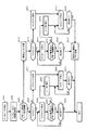
図2は、本実施例のデータ受信装置のデジタルデータ再生の動作を示すフローチャートである。
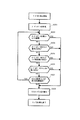
図3は、本実施例のデータ受信装置のモード切り換えを説明するフローチャートである。
図2において、制御部7は、デジタルデータ受信部1がデジタルデータを受信すると(ステップ201)、当該デジタルデータからID情報を取得する(ステップ202)。
An operation of reproducing digital data in the data receiving apparatus of this embodiment will be described.
FIG. 2 is a flowchart showing the digital data reproduction operation of the data receiving apparatus of this embodiment.
FIG. 3 is a flowchart for explaining mode switching of the data receiving apparatus of this embodiment.
In FIG. 2, when the digital data receiving unit 1 receives digital data (step 201), the
制御部7は、当該デジタルデータから取得したID情報とメモリに記憶しているID情報とを参照し、接続されているデータ送信装置から以前にデジタルデータを受信したことがあるか否かを判断する(ステップ203)。
The
接続されているデータ送信装置から以前にデジタルデータを受信したことがある場合(ステップ203)、制御部7は、さらにメモリに記憶されている基準クロック情報を参照し、以前にデジタルデータを受信した際に使用した基準クロックにVCXO基準クロックを用いたか否かを判断する(ステップ204)。
When the digital data has been received from the connected data transmission device before (step 203), the
以前にデジタルデータを受信した際に使用した基準クロックがVCXO基準クロックである場合(ステップ204)、制御部7は、マスタークロック生成部6をVCXOモードに設定し、マスタークロック生成部6にVCXOクロック発振部4が発振したVCXO基準クロックを用いてマスタークロックを生成させ、当該マスタークロックを信号処理部2及び出力部3に出力させ、信号処理部2及び出力部3にオーディオデータの再生を行わせる(ステップ205)。
When the reference clock used when the digital data was previously received is the VCXO reference clock (step 204), the
制御部7は、マスタークロック生成部6からVCXO基準クロックを用いたマスタークロックを出力させた後、デジタルデータのクロックに基づく制御電圧によりVCXOクロック発振部4から発振するVCXO基準クロックが第1切換閾値の範囲内か否かを(ステップ206)、当該デジタルデータの再生が終了するまで監視する(ステップ207)。
The
デジタルデータ受信部1が受信するデジタルデータの再生中に、デジタルデータのクロックに基づく制御電圧によりVCXOクロック発振部4から発振するVCXO基準クロックが第1切換閾値の範囲から外れた場合(ステップ206)、制御部7は、マスタークロック生成部6を制御し、基準クロックをVCXO基準クロックからVCO基準クロック(VCOモード)に切り換えるモード切り換えに移行する(ステップ208)。
When the VCXO reference clock oscillated from the VCXO
モード切り換えの処理(ステップ208)について説明する。
図3において、制御部7は、オーディオデータを監視し(ステップ301)、デジタルデータ受信部1に入力したデジタルデータのオーディオデータが微小レベル期間か否かを検出する(ステップ302)。当該オーディオデータが微小レベル期間の場合(ステップ302)、マスタークロック生成部6を制御し、VCOモードに切り換え(ステップ303)、モード切り換えを終了する。
The mode switching process (step 208) will be described.
In FIG. 3, the
デジタルデータ受信部1に入力したデジタルデータのオーディオデータが微小レベル期間でない場合(ステップ302)、当該オーディオデータのトラックが変わった(トラック番号の変化)か否かを検出する(ステップ304)。当該オーディオデータのトラックが変わった場合(ステップ304)、マスタークロック生成部6を制御し、VCOモードに切り換え(ステップ303)、モード切り換えを終了する。
If the audio data of the digital data input to the digital data receiving unit 1 is not in a very low level period (step 302), it is detected whether or not the track of the audio data has changed (track number change) (step 304). When the track of the audio data has changed (step 304), the master
デジタルデータ受信部1に入力したデジタルデータのオーディオデータのトラックが変わってない場合(ステップ304)、当該オーディオデータのサンプリング周波数が変わったか否かを検出する(ステップ305)。当該オーディオデータのサンプリング周波数が変わった場合(ステップ305)、マスタークロック生成部6を制御し、VCOモードに切り換え(ステップ303)、モード切り換えを終了する。
When the track of the audio data of the digital data input to the digital data receiving unit 1 has not changed (step 304), it is detected whether the sampling frequency of the audio data has changed (step 305). When the sampling frequency of the audio data has changed (step 305), the master
デジタルデータ受信部1に入力したデジタルデータのオーディオデータのサンプリング周波数が変わってない場合(ステップ305)、当該オーディオデータのチャンネル数が変わったか否かを検出する(ステップ306)。当該オーディオデータのチャンネル数が変わった場合(ステップ306)、マスタークロック生成部6を制御し、VCOモードに切り換え(ステップ303)、モード切り換えを終了する。
When the sampling frequency of the audio data of the digital data input to the digital data receiving unit 1 has not changed (step 305), it is detected whether the number of channels of the audio data has changed (step 306). If the number of channels of the audio data has changed (step 306), the master
デジタルデータ受信部1に入力したデジタルデータのオーディオデータのチャンネル数が変わってない場合(ステップ306)、デジタルデータのクロックに基づく制御電圧によりVCXOクロック発振部4から発振するVCXO基準クロックが第2切換閾値の範囲から外れたか否かを検出する(ステップ307)。VCXO基準クロックが第2切換閾値の範囲内の場合(ステップ307)、ステップ302に戻り、ステップ302からステップ307の処理を繰り返す。
When the number of channels of audio data of the digital data input to the digital data receiving unit 1 has not changed (step 306), the VCXO reference clock oscillated from the VCXO
VCXO基準クロックが第2切換閾値の範囲から外れた場合(ステップ307)、マスタークロック生成部6を制御し、VCOモードに切り換え(ステップ303)、モード切り換えを終了する。
When the VCXO reference clock is out of the second switching threshold range (step 307), the master
図2において、VCOモードに切り換わった後(ステップ208)、制御部7は、マスタークロック生成部6を制御し、VCOクロック発振部5が発振したVCO基準クロックを用いてマスタークロックを生成させ、当該マスタークロックを信号処理部2及び出力部3に出力させ、信号処理部2及び出力部3にオーディオデータの再生を開始させる(ステップ209)。
In FIG. 2, after switching to the VCO mode (step 208), the
そして、制御部7は、マスタークロック生成部6からVCO基準クロックを用いたマスタークロックを出力させオーディオデータの再生を開始させた後(ステップ209)、当該オーディオデータの再生が終了するまでVCOモードでの再生を継続する(ステップ210)。
Then, the
ステップ204において、接続されているデータ送信装置から以前にデジタルデータを受信した際に使用した基準クロックがVCXO基準クロックでない場合(VCO基準クロックの場合)、制御部7は、マスタークロック生成部6をVCOモードに設定し(ステップ211)、VCOクロック発振部5が発振したVCO基準クロックを用いてマスタークロックを生成させ、当該マスタークロックを信号処理部2及び出力部3に出力させ、信号処理部2及び出力部3にオーディオデータを再生させる(ステップ209)。
In step 204, when the reference clock used when digital data was previously received from the connected data transmission device is not the VCXO reference clock (in the case of the VCO reference clock), the
そして、制御部7は、オーディオデータの再生を開始させた後(ステップ209)、当該オーディオデータの再生が終了するまでVCOモードによるオーディオデータの再生を継続する(ステップ210)。
Then, after starting the reproduction of the audio data (step 209), the
また、デジタルデータ受信部1がデジタルデータを受信し(ステップ201)、制御部7が当該デジタルデータからID情報を取得し(ステップ202)、接続されているデータ送信装置から以前にデジタルデータを受信したことがない場合(ステップ203)、制御部7は、取得したID情報をメモリに記憶する(ステップ212)。
Also, the digital data receiving unit 1 receives the digital data (step 201), the
そして、制御部7は、最初に、VCXOモードに設定し、マスタークロック生成部6にVCXO基準クロックを用いてマスタークロックを生成させ、生成したマスタークロックが受信したテジタルデータのクロックに同期するか否か(VCXO基準クロックが第1切り換え閾値内か否か)を確認する(ステップ213)。
Then, the
VCXO基準クロックを用いて生成したマスタークロックがテジタルデータのクロックに同期する場合(ステップ213)、制御部7は、マスタークロックを信号処理部2及び出力部3に供給し、VCXOモードで再生を開始する(ステップ214)。
When the master clock generated using the VCXO reference clock is synchronized with the digital data clock (step 213), the
制御部7は、マスタークロック生成部6からVCXO基準クロックを用いたマスタークロックを出力させた後、デジタルデータのクロックに基づく制御電圧によりVCXOクロック発振部4から発振するVCXO基準クロックが第1切換閾値の範囲内か否かを(ステップ215)、当該デジタルデータの再生が終了するまで監視する(ステップ216)。
The
制御部7は、オーディオデータの再生が終了した場合(ステップ216)、メモリに基準クロックとして用いたVCXO基準クロックを基準クロック情報として記憶し(ステップ217)、終了する。
When the reproduction of the audio data is completed (step 216), the
デジタルデータ受信部1が受信するデジタルデータの再生中に、デジタルデータのクロックに基づく制御電圧によりVCXOクロック発振部4から発振するVCXO基準クロックが第1切換閾値の範囲から外れた場合(ステップ215)、制御部7は、マスタークロック生成部6を制御し、基準クロックをVCXO基準クロックからVCO基準クロック(VCOモード)に切り換えるモード切り換えに移行する(ステップ218)。
When the VCXO reference clock oscillated from the VCXO
ステップ218におけるモード切り換えは、前述したステップ208のモード切り換えと同じ処理のため説明を省略する。 Since the mode switching in step 218 is the same process as the mode switching in step 208 described above, description thereof is omitted.
VCOモードに切り換わった後(ステップ218)、制御部7は、マスタークロック生成部6を制御し、VCOクロック発振部5が発振したVCO基準クロックを用いてマスタークロックを生成させ、当該マスタークロックを信号処理部2及び出力部3に出力させ、信号処理部2及び出力部3にオーディオデータの再生を開始させる(ステップ219)。
After switching to the VCO mode (step 218), the
そして、制御部7は、マスタークロック生成部6からVCO基準クロックを用いたマスタークロックを出力させオーディオデータの再生を開始させた後(ステップ219)、当該オーディオデータの再生が終了するまでVCOモードでの再生を継続する(ステップ220)。
Then, the
ステップ213において、接続されているデータ送信装置から以前にデジタルデータを受信した際に使用した基準クロックがVCXO基準クロックでない場合(VCO基準クロックの場合)、制御部7は、マスタークロック生成部6をVCOモードに設定し(ステップ221)、VCOクロック発振部5が発振したVCO基準クロックを用いてマスタークロックを生成させ、当該マスタークロックを信号処理部2及び出力部3に出力させ、信号処理部2及び出力部3にオーディオデータを再生させる(ステップ219)。
In step 213, when the reference clock used when the digital data has been received from the connected data transmission device is not the VCXO reference clock (in the case of the VCO reference clock), the
そして、制御部7は、オーディオデータの再生を開始させた後(ステップ219)、当該オーディオデータの再生が終了するまでVCOモードによるオーディオデータの再生を継続する(ステップ220)。
Then, after starting the reproduction of the audio data (Step 219), the
制御部7は、オーディオデータの再生が終了した場合(ステップ220)、メモリに基準クロックとして用いたVCO基準クロックを基準クロック情報として記憶し(ステップ217)、終了する。
When the reproduction of the audio data is finished (step 220), the
以上のように、データ受信装置は、VCXO基準クロックを発振するVCXOクロック発振部4とVCO基準クロックを発振するVCOクロック発振部5を備え、データ送信装置から送信されてくるID情報とメモリに記憶した基準クロック情報とに基づいて、送信されてくるデジタルデータに適合する基準クロックを用いてマスタークロックを生成し、そのマスタークロックによりオーディオデータの再生を行う。
As described above, the data receiving device includes the VCXO
また、データ受信装置は、最初に、データ送信装置から送信されてきたデジタルデータに同期するマスタークロックをVCXO基準クロックを用いて生成しオーディオデータの再生を行い、デジタルデータのクロック周波数に基づく制御電圧によりVCXOクロック発振部が発振したVCXO基準クロックが第1切換閾値の範囲から外れた場合に、モード切り換えによりVCXOモードからVCOモードに切り換えてVCOモードに固定し、VCO基準クロックを用いてマスタークロックを生成しオーディオデータを再生する。 In addition, the data receiving apparatus first generates a master clock synchronized with the digital data transmitted from the data transmitting apparatus using the VCXO reference clock, reproduces the audio data, and controls the control voltage based on the clock frequency of the digital data. When the VCXO reference clock oscillated by the VCXO clock oscillation unit is out of the first switching threshold range, the VCXO mode is switched from the VCXO mode to the VCO mode by mode switching, and the master clock is set using the VCO reference clock. Generate and play audio data.
このことにより、VCXO基準クロックを用いて生成したマスタークロックがデジタルデータのクロックに同期する場合には、オーディオデータを音質劣化なく復元することができ、さらにVCXO基準クロックを用いて生成したマスタークロックがデジタルデータのクロックに同期しない場合或いはオーディオデータの再生中にVCXO基準クロックが第1切換閾値の範囲から外れた場合でも、VCO基準クロックを用いたマスタークロックに切り換えて再生を行うため、オーディオデータが途切れたり或いはノイズが発生することがない。 As a result, when the master clock generated using the VCXO reference clock is synchronized with the clock of the digital data, the audio data can be restored without deterioration in sound quality, and the master clock generated using the VCXO reference clock is Even if the VCXO reference clock is out of the range of the first switching threshold during reproduction of audio data when the digital data is not synchronized with the clock of the digital data, reproduction is performed by switching to the master clock using the VCO reference clock. There is no interruption or noise.
また、VCXO基準クロックからVCO基準クロックの切り換えにおいては、オーディオデータの微小レベル期間或いはトラックが変わったときに基準クロックの切り換えを行うため、基準クロックの切り換えに伴い発生するノイズを聴取者に聴取しづらくし、ノイズ発生を目立たなくすることができる。 Also, when switching from the VCXO reference clock to the VCO reference clock, the reference clock is switched when the audio data has a very low level period or track, so the noise generated by the switching of the reference clock is heard by the listener. It is hard to make noise generation inconspicuous.
前述した実施例では、メモリに記憶された基準クロック情報としてVCO基準クロック(VCOモード)が記憶されている場合、或いは、VCXOモードでの再生中にVCXO基準クロックが第1切換閾値の範囲から外れた場合に、VCXO基準クロックからVCO基準クロックに切り換え、その後も基準クロックとしてVCO基準クロックを用いるVCOモードに固定してオーディオデータの再生を行う場合について説明したが、VCOモードでの再生中或いはVCXO基準クロックからVCO基準クロックに切り換えた後、予め定めた条件を満たした場合に、VCXO基準クロックに切り換えるようにしてもよい。 In the embodiment described above, when the VCO reference clock (VCO mode) is stored as the reference clock information stored in the memory, or during reproduction in the VCXO mode, the VCXO reference clock is out of the first switching threshold range. In the above description, the case where the VCXO reference clock is switched to the VCO reference clock and the audio data is reproduced after being fixed to the VCO mode using the VCO reference clock as the reference clock has been described. After switching from the reference clock to the VCO reference clock, when the predetermined condition is satisfied, the reference clock may be switched to the VCXO reference clock.
予め定めた条件とは、VCOモードでの再生中に、デジタルデータのクロック周波数を監視し、当該クロック周波数がVCXO基準クロックの第1切換閾値内であり、且つ、その状態が予め定めた期間連続したときに(例えば、複数のトラックのオーディオデータを再生した場合、または、複数の媒体を再生した場合)、予め定めた条件を満たしたものとする。 The predetermined condition is that the clock frequency of the digital data is monitored during reproduction in the VCO mode, the clock frequency is within the first switching threshold value of the VCXO reference clock, and the state continues for a predetermined period. (For example, when audio data of a plurality of tracks is reproduced or when a plurality of media are reproduced), it is assumed that a predetermined condition is satisfied.
例えば、データ送信装置において、何らかの原因により一瞬クロック周波数が乱れ、その乱れが影響し、データ受信装置が受信するデジタルデータのクロック周波数が変化する場合がある。この場合、データ受信装置は、VCXO基準クロックが第1切換閾値を越え、オーディオデータの微小レベル期間又はトラックが変わった場合、モード切り換えによりVCXOモードからVCOモードへの切り換えを行う。 For example, in a data transmission device, the clock frequency may be disturbed for some reason, and the disturbance may affect the clock frequency of digital data received by the data reception device. In this case, when the VCXO reference clock exceeds the first switching threshold and the minute level period or track of the audio data changes, the data receiving apparatus switches from the VCXO mode to the VCO mode by mode switching.
データ送信装置において、クロック周波数が一瞬乱れた後、直ぐに正常なクロック周波数にもどった場合でも、データ受信装置においては、それ以降の再生にはVCO基準クロックを用いて生成したマスタークロック(VCOモード)によりオーディオデータの再生が行われ、音質が低いオーディオデータが再生され続けることになる。 In the data transmission device, even if the clock frequency is momentarily disturbed and then immediately returns to the normal clock frequency, the data reception device in the data reception device uses the VCO reference clock for the subsequent reproduction (VCO mode). Thus, the audio data is reproduced, and the audio data with low sound quality is continuously reproduced.
このような、データ送信装置における突発的なクロック周波数の乱れによりデータ受信装置におけるVCXO基準クロックが第1切換閾値を外れた場合でも、予め定めた条件を満たしたときに、VCXOモードに切り換え、高音質なオーディオデータの再生をするようにする。 Even when the VCXO reference clock in the data receiving apparatus deviates from the first switching threshold due to the sudden clock frequency disturbance in the data transmitting apparatus, when the predetermined condition is satisfied, the VCXO mode is switched to the VCXO mode. Play sound quality audio data.
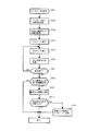
図4は、本発明のデータ受信装置における他の実施例のオーディオデータ再生の動作を説明するフローチャートである。
本実施例では、デジタルデータ受信部1が受信したデジタルデータは、以前にデジタルデータを受信したことがあるデータ送信装置から送信されたデジタルデータであり、ID情報に当該データ送信装置における基準クロック情報としてVCO基準クロック(VCOモード)が記憶され、VCOモードでの再生において予め定めた条件を満たした場合を例にあげ説明する。
FIG. 4 is a flowchart for explaining the operation of reproducing audio data in another embodiment of the data receiving apparatus of the present invention.
In this embodiment, the digital data received by the digital data receiving unit 1 is digital data transmitted from a data transmission apparatus that has received digital data before, and the reference clock information in the data transmission apparatus is included in the ID information. As an example, a case where a VCO reference clock (VCO mode) is stored and a predetermined condition is satisfied in reproduction in the VCO mode will be described.
制御部7は、デジタルデータ受信部1がデジタルオーディオデータを受信すると(ステップ401)、当該デジタルデータからID情報を取得する(ステップ402)。
When the digital data receiving unit 1 receives the digital audio data (step 401), the
制御部7は、当該デジタルデータから取得したID情報に基づいて、当該ID情報に対応する基準クロック情報を取得する(ステップ403)。
Based on the ID information acquired from the digital data, the
制御部7は、VCXOモードを設定し(ステップ404)、マスタークロック生成部6にVCO基準クロックを用いてマスタークロックを生成させ、信号処理部2及び出力部3にマスタークロックを出力させ、信号処理部2及び出力部3にオーディオデータの再生を行わせる(ステップ405)。
The
制御部7は、オーディオデータの再生中、デジタルデータ受信部1が受信するデジタルデータのクロック周波数に基づく制御電圧によりVCOクロック発振部5が発振するVCO基準クロックが第1切換閾値内であるか否かを監視する(ステップ405)。
The
制御部7は、VCO基準クロックの監視をオーディオデータの再生が終了するまで行い(ステップ407)、オーディオデータの再生が終了した時点でVCO基準クロックが第1切換閾値内であったか否を判断する(ステップ408)。
The
VCO基準クロックが第1切換閾値内であった場合(ステップ408)、制御部7は、メモリの基準クロック情報に当該オーディオデータの再生においてVCO基準クロックが第1切換閾値内であった旨を履歴情報として記憶する(ステップ409)。VCO基準クロックが第1切換閾値内でなかった場合(ステップ408)、処理を終了し、次のデジタルデータの入力まで待機する。
When the VCO reference clock is within the first switching threshold (step 408), the
制御部7は、メモリの基準クロック情報にVCO基準クロックが第1切換閾値内であったことを履歴情報として記憶した後(ステップ409)、メモリに記憶されているID情報と履歴情報に基づいて当該データ送信装置から送信されたオーディオオデータの再生が予め定めた条件を満たしているか否かを判別する(ステップ410)。
The
データ送信装置から送信されたオーディオデータの再生が予め定めた条件を満たしている場合(ステップ410)、メモリに記憶されている当該ID情報に対応する基準クロック情報をVCXOモードに書き換え(ステップ411)、処理を終了し、次のデジタルオーディオデータの入力まで待機する。当該データ送信装置から送信されたオーディオデータの再生が予め定めた条件を満たしてない場合(ステップ410)、処理を終了し、次のデジタルデータの入力まで待機する。 When the reproduction of the audio data transmitted from the data transmitting apparatus satisfies a predetermined condition (step 410), the reference clock information corresponding to the ID information stored in the memory is rewritten to the VCXO mode (step 411). , The process is terminated, and the process waits for the next input of digital audio data. If the reproduction of the audio data transmitted from the data transmitting apparatus does not satisfy the predetermined condition (step 410), the process is terminated and the process waits until the next digital data is input.
このことにより、次に当該ID情報のデータ送信装置からデジタルデータが送信されてきた場合、データ受信装置の制御部7は、メモリに記憶されている基準クロック情報に基づいて、最初にVCXOモードを設定し、オーディオデータの再生を行う。
As a result, when digital data is next transmitted from the data transmission device of the ID information, the
この結果、データ送信装置から送信されたデジタルデータがVCOモードに設定された或いは切り換えられた場合でも、オーディデータの再生が予め定めた条件を満たした場合、設定されるモードがVCXOモードに切り換えられ、VCXOモードでオーディオデータが再生されるため、高音質でオーディオデータを再生することができる。 As a result, even when the digital data transmitted from the data transmission device is set or switched to the VCO mode, the set mode is switched to the VCXO mode if the reproduction of the audio data satisfies a predetermined condition. Since the audio data is reproduced in the VCXO mode, the audio data can be reproduced with high sound quality.
1・・・デジタルデータ受信部、2・・・信号処理部、3・・・出力部、4・・・VCXOクロック発振部、5・・・VCOクロク発振部、6・・・マスタークロック生成部、7・・・制御部。
DESCRIPTION OF SYMBOLS 1 ... Digital data receiving part, 2 ... Signal processing part, 3 ... Output part, 4 ... VCXO clock oscillation part, 5 ... VCO clock oscillation part, 6 ... Master clock generation part , 7... Control unit.
Claims (4)
4. The data receiving device according to claim 3, wherein the control unit monitors the VCXO reference clock based on a clock frequency of the received digital data during reproduction of audio data, and the VCXO reference clock frequency is the first switching. A reference clock used to generate a master clock by controlling the master clock generator when the VCXO clock oscillator deviates from a threshold value range and deviates from a second switching threshold range indicating the allowable frequency range of the clock that can be oscillated by the VCXO clock oscillator. Is switched from the VCXO reference clock to the VCO reference clock.
Priority Applications (1)
| Application Number | Priority Date | Filing Date | Title |
|---|---|---|---|
| JP2004105339A JP2005295071A (en) | 2004-03-31 | 2004-03-31 | Data receiver |
Applications Claiming Priority (1)
| Application Number | Priority Date | Filing Date | Title |
|---|---|---|---|
| JP2004105339A JP2005295071A (en) | 2004-03-31 | 2004-03-31 | Data receiver |
Publications (1)
| Publication Number | Publication Date |
|---|---|
| JP2005295071A true JP2005295071A (en) | 2005-10-20 |
Family
ID=35327545
Family Applications (1)
| Application Number | Title | Priority Date | Filing Date |
|---|---|---|---|
| JP2004105339A Withdrawn JP2005295071A (en) | 2004-03-31 | 2004-03-31 | Data receiver |
Country Status (1)
| Country | Link |
|---|---|
| JP (1) | JP2005295071A (en) |
Cited By (1)
| Publication number | Priority date | Publication date | Assignee | Title |
|---|---|---|---|---|
| JP2010165403A (en) * | 2009-01-14 | 2010-07-29 | Zoom Corp | Multitrack recorder and synchronous recording method using a plurality of multitrack recorders |
-
2004
- 2004-03-31 JP JP2004105339A patent/JP2005295071A/en not_active Withdrawn
Cited By (1)
| Publication number | Priority date | Publication date | Assignee | Title |
|---|---|---|---|---|
| JP2010165403A (en) * | 2009-01-14 | 2010-07-29 | Zoom Corp | Multitrack recorder and synchronous recording method using a plurality of multitrack recorders |
Similar Documents
| Publication | Publication Date | Title |
|---|---|---|
| JP4880068B2 (en) | Transmission device, reception device, and content reproduction system | |
| JP2013085224A (en) | Content data transmission system and content data transmission method | |
| JP2010165403A (en) | Multitrack recorder and synchronous recording method using a plurality of multitrack recorders | |
| US20070091935A1 (en) | Reference clock recovery circuit and data receiving apparatus | |
| US20090257453A1 (en) | Transmission apparatus and receiving apparatus | |
| JPH1051314A (en) | Reference clock generation device and decoding device | |
| JP2010154418A (en) | Method and device for wirelessly transmitting video | |
| JP3928519B2 (en) | Digital signal transmission system and method, and receiving apparatus and method | |
| JP4476131B2 (en) | Data transmission device, data reception device, and data transmission / reception system | |
| JP2007013853A (en) | Audio processing apparatus | |
| JP4380598B2 (en) | Receiving apparatus and receiving method | |
| EP2302935B1 (en) | Method and device for clock recovery | |
| JP5094478B2 (en) | Receiver | |
| JP2004253945A (en) | Signal phase synchronization device and signal phase synchronization method | |
| JP3216328B2 (en) | Digital priority input switching circuit | |
| JP2006246185A (en) | Wireless video transmission system | |
| JP4625350B2 (en) | Data transmission device, data reception device, and data transmission / reception system | |
| JP4345778B2 (en) | Digital signal transmission system and method, transmission apparatus and method, and reception apparatus and method | |
| JP5666409B2 (en) | Content data transmission system, content reproduction device, content output device, and content data transmission method | |
| JP2007295514A (en) | Data receiver | |
| JP3386506B2 (en) | Information recording / reproducing device | |
| JP2007280584A (en) | Data receiver | |
| JPH11232795A (en) | Bit clock regeneration device | |
| KR200249569Y1 (en) | CD player audio distortion canceller | |
| JP2005269485A (en) | Communication device with clock circuit |
Legal Events
| Date | Code | Title | Description |
|---|---|---|---|
| A300 | Withdrawal of application because of no request for examination |
Free format text: JAPANESE INTERMEDIATE CODE: A300 Effective date: 20070605 |