JP2005295002A - ANTENNA DEVICE AND MOBILE COMMUNICATION TERMINAL DEVICE - Google Patents
ANTENNA DEVICE AND MOBILE COMMUNICATION TERMINAL DEVICE Download PDFInfo
- Publication number
- JP2005295002A JP2005295002A JP2004104118A JP2004104118A JP2005295002A JP 2005295002 A JP2005295002 A JP 2005295002A JP 2004104118 A JP2004104118 A JP 2004104118A JP 2004104118 A JP2004104118 A JP 2004104118A JP 2005295002 A JP2005295002 A JP 2005295002A
- Authority
- JP
- Japan
- Prior art keywords
- antenna
- power
- feeding
- antenna device
- phase shifter
- Prior art date
- Legal status (The legal status is an assumption and is not a legal conclusion. Google has not performed a legal analysis and makes no representation as to the accuracy of the status listed.)
- Pending
Links
Images

Landscapes
- Variable-Direction Aerials And Aerial Arrays (AREA)
Abstract
Description
本発明は、移動通信端末装置などに用いるアンテナ装置に関する。 The present invention relates to an antenna device used for a mobile communication terminal device or the like.
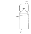
従来、移動体通信端末に使用するアンテナ装置として、図6に示すように、2つのアンテナ素子102を設けて位相器109を介して給電装置103に接続することでこれらのアンテナ素子102にそれぞれ逆相に給電し、この給電装置103を介して有限地板101に接地した構成したものが知られている(例えば、特許文献1、2参照)。このアンテナ装置によれば、2素子のアンテナ間の位相差を任意に調整することができ、アンテナの指向性を人体に向けないようにして、人体頭部近傍電磁界を減少させ、比吸収率(SAR:Specific Absorption Rate)を低減することができる。
Conventionally, as an antenna apparatus used for a mobile communication terminal, as shown in FIG. 6, two
しかしながら、特許文献1、2に記載のアンテナ装置は、2素子のアンテナに同時に給電する際に電力分配器および位相器を使用しており、特に高周波数帯域において電力分配器および位相器の損失が大きく送信電力レベルが劣化するという問題があった。
However, the antenna devices described in
本発明は、このような従来の問題を解決するためになされたものであり、送信時において電力分配器および位相器を使用することなくSARを低減することができるアンテナ装置および移動通信端末装置を提供することを目的とするものである。 The present invention has been made to solve such a conventional problem. An antenna apparatus and a mobile communication terminal apparatus capable of reducing SAR without using a power distributor and phase shifter at the time of transmission are provided. It is intended to provide.
本発明のアンテナ装置は、給電装置およびこの給電装置を介して携帯端末用有限地板に接続した給電素子と、前記給電素子と所定の間隔を有して配置した無給電素子と、前記携帯端末用有限地板と前記無給電素子とを可変リアクタンス素子によって接続する構成を有する。 An antenna device of the present invention includes a power feeding device, a power feeding element connected to a finite ground plane for a portable terminal through the power feeding device, a parasitic element arranged with a predetermined distance from the power feeding element, and the portable terminal A finite ground plane and the parasitic element are connected by a variable reactance element.
この構成により、電力分配器および位相器を使用することなく可変リアクタンスによって人体近傍等の電磁界分布を変化させることができる。 With this configuration, the electromagnetic field distribution in the vicinity of the human body can be changed by variable reactance without using a power distributor and phase shifter.
また、本発明のアンテナ装置は、給電装置と、前記給電装置からの電力を分配する電力分配器と、前記電力分配器の複数の出力にそれぞれ接続された電力制御装置と、前記電力制御装置の出力にそれぞれ接続された位相器と、前記位相器の一つに接続され前記給電装置を介して携帯端末用有限地板に接続された給電素子と、前記給電素子と所定の間隔を有して配置されたアンテナ素子と、前記携帯端末用有限地板に接続されたリアクタンス素子と、前記アンテナ素子を前記位相器または前記リアクタンス素子に切り替えて接続するスイッチとを有し、前記スイッチは送信時には前記アンテナ素子を前記リアクタンス素子に接続し、受信時には前記アンテナ素子を前記位相器に接続する構成を有する。 The antenna device according to the present invention includes: a power feeding device; a power distributor that distributes power from the power feeding device; a power control device that is connected to each of a plurality of outputs of the power distributor; and A phase shifter connected to each of the outputs, a feed element connected to one of the phase shifters and connected to a finite ground plane for a portable terminal via the feed device, and a predetermined distance from the feed element An antenna element, a reactance element connected to the finite ground plane for the portable terminal, and a switch for switching the antenna element to the phase shifter or the reactance element, and the switch is configured to transmit the antenna element during transmission. Is connected to the reactance element, and the antenna element is connected to the phase shifter during reception.
この構成により、送信時には電力分配器および位相器を使用せずに人体近傍等の電磁界分布を変化させることができ、受信時には給電電力と位相の制御により、任意の方向にアンテナ装置の指向性を向け、干渉波を除去することが可能になり、受信感度を改善できる。 With this configuration, the electromagnetic field distribution in the vicinity of the human body can be changed without using a power divider and phaser during transmission, and the directivity of the antenna device can be controlled in any direction by controlling the feed power and phase during reception. The interference sensitivity can be removed and the reception sensitivity can be improved.
また、本発明のアンテナ装置は、上記いずれかのアンテナ装置を複数有し、これらのアンテナ装置はそれぞれ独立した任意の偏波を送受信するものであることを特徴とする。
この構成により、例えば垂直偏波と水平偏波など、複数の偏波が送受信可能になる。
The antenna device of the present invention includes a plurality of any of the antenna devices described above, and these antenna devices transmit and receive arbitrary independent polarized waves.
With this configuration, it is possible to transmit and receive a plurality of polarizations such as vertical polarization and horizontal polarization.
また、本発明のアンテナ装置は、前記複数のアンテナ装置を切り替えるスイッチを有し、前記スイッチを切り替えることによりダイバーシティ送受信を行うことを特徴とする。
この構成により、偏波ダイバーシティ送受信が可能となり、受信感度を改善することができる。
Moreover, the antenna device of the present invention has a switch for switching the plurality of antenna devices, and performs diversity transmission / reception by switching the switch.
With this configuration, polarization diversity transmission / reception is possible, and reception sensitivity can be improved.
また。本発明の移動通信端末装置は、上記いずれかのアンテナ装置が搭載されている構成を有する。
この構成により、SARが低く、受信感度の良い移動通信端末を提供することができる。
Also. The mobile communication terminal device of the present invention has a configuration in which any one of the above antenna devices is mounted.
With this configuration, it is possible to provide a mobile communication terminal with low SAR and good reception sensitivity.
本発明によれば、送信時において電力分配器および位相器を使用することなくSARを低減することができる。 According to the present invention, it is possible to reduce SAR without using a power distributor and phase shifter during transmission.
以下、本発明の実施の形態について図面を用いて説明する。 Hereinafter, embodiments of the present invention will be described with reference to the drawings.
(第1の実施の形態)
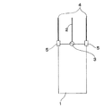
図1は、本発明の第1の実施の形態におけるアンテナ装置の概略図である。
(First embodiment)
FIG. 1 is a schematic diagram of an antenna device according to a first embodiment of the present invention.
本発明の第1の実施の形態におけるアンテナ装置は、図1に示すように、給電素子2および無給電素子4を備え、給電素子2は給電装置3に接続され、この給電装置3を介して携帯端末用有限地板1に接続されている。また、無給電素子4は給電素子2と一定の間隔を置いて両側に2つ配置され、この無給電素子4をそれぞれ携帯端末用有限地板1に接地された可変リアクタンス素子5に接続するように構成されている。
As shown in FIG. 1, the antenna device according to the first embodiment of the present invention includes a
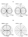
上記構成において、可変リアクタンス素子5における可変リアクタンスの定数により、給電素子2と無給電素子4との相互インピーダンスが変化し、これに伴い近傍の電磁界も変化する。このアンテナ装置の近傍に人体が位置する場合、人体近傍において、あるリアクタンス定数を決定することにより人体方向に影響の少ない近傍電磁界を形成することができる。図2(a),(b)にリアクタンス定数を変化させたときのアンテナ装置の代表的な指向性パターンを示す。x方向を人体方向とした場合、図2(a)に示すリアクタンス定数αの場合は人体方向に大きく放射しているのに対し、図2(b)に示すリアクタンス定数βの場合は人体方向に極めて弱い放射(null)が得られている。
In the above configuration, the mutual impedance of the
このように、本実施の形態におけるアンテナ装置によれば、人体近傍の電磁界分布を可変リアクタンスにより変えることができ、人体近傍のSARを低減することができる。 Thus, according to the antenna device in the present embodiment, the electromagnetic field distribution in the vicinity of the human body can be changed by the variable reactance, and the SAR in the vicinity of the human body can be reduced.
また、分配器および位相器が不要であるため、分配器および位相器の損失を無くすることができ、分配器および位相器を使用した同時給電の場合と比較して送信電力レベルを改善することができる。 In addition, since a distributor and a phase shifter are unnecessary, the loss of the distributor and the phase shifter can be eliminated, and the transmission power level can be improved as compared with the case of simultaneous feeding using the distributor and the phase shifter. Can do.
なお、本実施の形態では、無給電素子を2素子としているが、無給電素子を1素子または3素子以上としても良く、このようにすれば、より多くの状況に対応してSARを低減することができる。 In this embodiment, the parasitic elements are two elements. However, the parasitic elements may be one element or three or more elements. In this way, the SAR is reduced corresponding to more situations. be able to.
(第2の実施の形態)
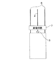
図3は、本発明の第2の実施の形態におけるアンテナ装置の概略図である。
(Second Embodiment)
FIG. 3 is a schematic diagram of an antenna device according to the second embodiment of the present invention.
本発明の第2の実施の形態におけるアンテナ装置は、図3に示すように、給電素子2とアンテナ素子6が一定の間隔を置いて配置され、これらの給電素子2およびアンテナ素子6を給電回路7に接続されている。また、給電素子2は給電回路7を介して給電装置3に接続され、さらに給電装置3を介して携帯端末用有限地板1に接続されている。また、アンテナ素子6は給電回路7を介して携帯端末用有限地板1に接続されている。
In the antenna device according to the second embodiment of the present invention, as shown in FIG. 3, the
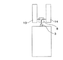
図4に給電回路7の内部構造を示す。給電回路7は、給電素子2およびアンテナ素子6にそれぞれ接続される位相器9と、これらの位相器9にそれぞれ接続される振幅制御装置10と、これらの振幅制御装置10に給電装置3からの電力を分配する電力分配/合成器11と、携帯端末用有限地板1に接続されるリアクタンス素子12と、アンテナ素子6を位相器9またはリアクタンス素子12に切り替えて接続するスイッチ素子8とを有している。
FIG. 4 shows the internal structure of the
この給電回路7において、受信の場合は、スイッチ素子8を位相器9側に切り替えて、位相器9と振幅制御装置10により給電素子2とアンテナ素子6に任意の重みを持たせる。なお、給電装置3から給電回路7への入出力は電力分配/合成器11によって行う。また、送信の場合はスイッチ素子8をリアクタンス素子12側に切り替えて、リアクタンス素子12の他端は携帯端末用有限地板1に接続する。リアクタンス素子12は、第1の実施の形態と同様に、あらかじめ人体近傍電磁界および人体方向の指向性が弱くなるような定数としておく。
In the
このように、本実施の形態におけるアンテナ装置によれば、送信時はリアクタンス素子により人体近傍の電磁界分布を弱くすることでSARを低減させることができ、受信時は振幅制御装置と位相器により指向性を任意に変更することにより干渉波成分を除去し、所望波方向に強い指向性を向けることにより、受信感度の良いアンテナ装置を提供することができる。 Thus, according to the antenna device in the present embodiment, the SAR can be reduced by weakening the electromagnetic field distribution near the human body by the reactance element at the time of transmission, and by the amplitude control device and the phaser at the time of reception. An antenna device with good reception sensitivity can be provided by removing interference wave components by arbitrarily changing the directivity and directing strong directivity in the desired wave direction.
なお、本実施の形態では、給電素子を1本、アンテナ素子を2本としているが、それぞれの素子の本数はそれ以上で良く、このようにすれば、干渉波除去能力がさらに高まり、受信感度を改善することができる。 In the present embodiment, one feeding element and two antenna elements are used. However, the number of each element may be more than this, and in this way, the interference wave removal capability is further increased, and reception sensitivity is increased. Can be improved.
(第3の実施の形態)
図5は、本発明の第3の実施の形態におけるアンテナ装置の概略図である。
(Third embodiment)
FIG. 5 is a schematic diagram of an antenna device according to the third embodiment of the present invention.
本発明の第3の実施の形態におけるアンテナ装置は、図5に示すように、垂直偏波が送受信可能なアンテナ装置13と、水平偏波が送受信可能なアンテナ装置14とを備え、これらのアンテナ装置13、14がスイッチ素子8を介して給電装置3、携帯端末用有限地板1に接続されている。アンテナ装置13、14は、上記第1および第2の実施の形態にて説明したいずれかの構成を有している。スイッチ素子8は、アンテナ装置13とアンテナ装置14のいずれかを給電装置3に接続するように接続を切り替えることにより、ダイバーシティ送受信を行うものである。
As shown in FIG. 5, the antenna device according to the third embodiment of the present invention includes an
このように、本実施の形態におけるアンテナ装置によれば、垂直および水平両偏波を送受信することができ、偏波ダイバーシティ効果により、より高い受信感度を得ることができる。 Thus, according to the antenna device in the present embodiment, both vertical and horizontal polarized waves can be transmitted and received, and higher reception sensitivity can be obtained due to the polarization diversity effect.
なお、本実施の形態におけるアンテナ装置では、垂直偏波および水平偏波を受信できるアンテナ装置としているが、その他の偏波を受信できるアンテナ装置を使用しても良く、このようにすれば、様々な環境において受信感度の高いアンテナ装置を提供することができる。 In the antenna device according to the present embodiment, an antenna device that can receive vertical polarization and horizontal polarization is used. However, an antenna device that can receive other polarizations may be used. It is possible to provide an antenna device with high reception sensitivity in a difficult environment.
なお、本実施の形態におけるアンテナ装置では、アンテナ装置を2つとしているが、3つ以上でも良く、このようにすればより高感度な偏波ダイバーシティ受信が可能となり、受信感度が向上する。 In the antenna device according to the present embodiment, two antenna devices are used. However, three or more antenna devices may be used, and in this way, more sensitive polarization diversity reception is possible and reception sensitivity is improved.
本発明は、送信時において電力分配器および位相器を使用することなくSARを低減することができ、高周波数帯域を使用するアンテナ装置およびこれを備えた移動通信端末装置などに有用である。 INDUSTRIAL APPLICABILITY The present invention can reduce SAR without using a power divider and phase shifter during transmission, and is useful for an antenna device using a high frequency band, a mobile communication terminal device including the antenna device, and the like.
1 携帯端末用有限地板
2 給電素子
3 給電装置
4 無給電素子
5 可変リアクタンス素子
6 アンテナ素子
7 給電回路
8 スイッチ素子
9 位相器
10 振幅制御装置
11 電力分配/合成器
12 リアクタンス素子
13 垂直偏波を受信するアンテナ装置
14 水平偏波を受信するアンテナ装置
DESCRIPTION OF
Claims (5)
Priority Applications (1)
| Application Number | Priority Date | Filing Date | Title |
|---|---|---|---|
| JP2004104118A JP2005295002A (en) | 2004-03-31 | 2004-03-31 | ANTENNA DEVICE AND MOBILE COMMUNICATION TERMINAL DEVICE |
Applications Claiming Priority (1)
| Application Number | Priority Date | Filing Date | Title |
|---|---|---|---|
| JP2004104118A JP2005295002A (en) | 2004-03-31 | 2004-03-31 | ANTENNA DEVICE AND MOBILE COMMUNICATION TERMINAL DEVICE |
Publications (1)
| Publication Number | Publication Date |
|---|---|
| JP2005295002A true JP2005295002A (en) | 2005-10-20 |
Family
ID=35327488
Family Applications (1)
| Application Number | Title | Priority Date | Filing Date |
|---|---|---|---|
| JP2004104118A Pending JP2005295002A (en) | 2004-03-31 | 2004-03-31 | ANTENNA DEVICE AND MOBILE COMMUNICATION TERMINAL DEVICE |
Country Status (1)
| Country | Link |
|---|---|
| JP (1) | JP2005295002A (en) |
Cited By (5)
| Publication number | Priority date | Publication date | Assignee | Title |
|---|---|---|---|---|
| US7528783B2 (en) | 2007-01-15 | 2009-05-05 | Panasonic Corporation | Antenna |
| CN102157778A (en) * | 2011-01-24 | 2011-08-17 | 中兴通讯股份有限公司 | Method and device for realizing SAR (Specific Absorption Rate) control |
| JP2012169814A (en) * | 2011-02-14 | 2012-09-06 | Sony Corp | Antenna device and communication device |
| WO2018123345A1 (en) * | 2016-12-27 | 2018-07-05 | 株式会社村田製作所 | Antenna device |
| CN110875516A (en) * | 2018-08-30 | 2020-03-10 | 联想(新加坡)私人有限公司 | Antenna devices and electronic equipment |
-
2004
- 2004-03-31 JP JP2004104118A patent/JP2005295002A/en active Pending
Cited By (10)
| Publication number | Priority date | Publication date | Assignee | Title |
|---|---|---|---|---|
| US7528783B2 (en) | 2007-01-15 | 2009-05-05 | Panasonic Corporation | Antenna |
| CN102157778A (en) * | 2011-01-24 | 2011-08-17 | 中兴通讯股份有限公司 | Method and device for realizing SAR (Specific Absorption Rate) control |
| CN102157778B (en) * | 2011-01-24 | 2015-04-01 | 中兴通讯股份有限公司 | Method and device for realizing SAR (Specific Absorption Rate) control |
| US9559415B2 (en) | 2011-01-24 | 2017-01-31 | Zte Corporation | Method and device for realizing specific absorption rate (SAR) control |
| JP2012169814A (en) * | 2011-02-14 | 2012-09-06 | Sony Corp | Antenna device and communication device |
| WO2018123345A1 (en) * | 2016-12-27 | 2018-07-05 | 株式会社村田製作所 | Antenna device |
| JPWO2018123345A1 (en) * | 2016-12-27 | 2019-07-11 | 株式会社村田製作所 | Antenna device |
| CN110121815A (en) * | 2016-12-27 | 2019-08-13 | 株式会社村田制作所 | Antenna assembly |
| CN110875516A (en) * | 2018-08-30 | 2020-03-10 | 联想(新加坡)私人有限公司 | Antenna devices and electronic equipment |
| US11081779B2 (en) | 2018-08-30 | 2021-08-03 | Lenovo (Singapore) Pte Ltd | Electronic device having an antenna |
Similar Documents
| Publication | Publication Date | Title |
|---|---|---|
| US11239572B2 (en) | Beam-steering reconfigurable antenna arrays | |
| JP6384550B2 (en) | Wireless communication module | |
| US20100007573A1 (en) | Multibeam antenna | |
| US9799954B2 (en) | Apparatus with multi-directional radiation capability using multiple antenna elements | |
| MXPA04005899A (en) | Antenna system. | |
| US11196160B2 (en) | Dual-polarized retrodirective array and multi-frequency antenna element | |
| KR101988382B1 (en) | Antenna device and electronic device with the same | |
| US20150333408A1 (en) | Antenna device and wireless transmission device | |
| WO2012118619A2 (en) | Tracking system with orthogonal polarizations and a retro-directive array | |
| EP1657831A1 (en) | Antenna and receiver apparatus using the same | |
| JP2015179950A (en) | Antenna device | |
| JP2005295002A (en) | ANTENNA DEVICE AND MOBILE COMMUNICATION TERMINAL DEVICE | |
| JP2009118494A (en) | Wireless relay device | |
| JP6100075B2 (en) | Array antenna and wireless communication device | |
| US11158945B2 (en) | Phased array antenna apparatus and control method therefor | |
| KR101971781B1 (en) | Method and apparatus for transmitting signals based on coupling antenna for in-band full-duplex in the wireless communication system | |
| US20190237880A1 (en) | Antenna system and antenna module | |
| JPH03254207A (en) | Antenna system | |
| JP2008022123A (en) | Antenna device | |
| KR101974156B1 (en) | TRANSMISSION array ANTENNA APPARATUS, WIRELESS POWER TRANSMISSION SYSTEM INCLUDING IT METHOD FOR RETRO-DIRECTIVE BEAM FORMING THEREOF | |
| JP2008017384A (en) | Antenna device | |
| JP2017085513A (en) | Antenna device | |
| JP2000138528A (en) | Antenna device | |
| JP4685879B2 (en) | An improved antenna for a radio base station in a cellular network | |
| KR20060076832A (en) | Wireless communication terminal having a function of reducing the absorption rate of electromagnetic waves by using multiple antennas |
Legal Events
| Date | Code | Title | Description |
|---|---|---|---|
| RD04 | Notification of resignation of power of attorney |
Free format text: JAPANESE INTERMEDIATE CODE: A7424 Effective date: 20060424 |