JP2005294825A - Improved color photodetector array and method of manufacturing the same - Google Patents
Improved color photodetector array and method of manufacturing the same Download PDFInfo
- Publication number
- JP2005294825A JP2005294825A JP2005076762A JP2005076762A JP2005294825A JP 2005294825 A JP2005294825 A JP 2005294825A JP 2005076762 A JP2005076762 A JP 2005076762A JP 2005076762 A JP2005076762 A JP 2005076762A JP 2005294825 A JP2005294825 A JP 2005294825A
- Authority
- JP
- Japan
- Prior art keywords
- filter
- trim
- wavelength
- color
- light
- Prior art date
- Legal status (The legal status is an assumption and is not a legal conclusion. Google has not performed a legal analysis and makes no representation as to the accuracy of the status listed.)
- Granted
Links
Images
Classifications
-
- G—PHYSICS
- G01—MEASURING; TESTING
- G01J—MEASUREMENT OF INTENSITY, VELOCITY, SPECTRAL CONTENT, POLARISATION, PHASE OR PULSE CHARACTERISTICS OF INFRARED, VISIBLE OR ULTRAVIOLET LIGHT; COLORIMETRY; RADIATION PYROMETRY
- G01J3/00—Spectrometry; Spectrophotometry; Monochromators; Measuring colours
- G01J3/46—Measurement of colour; Colour measuring devices, e.g. colorimeters
- G01J3/50—Measurement of colour; Colour measuring devices, e.g. colorimeters using electric radiation detectors
- G01J3/51—Measurement of colour; Colour measuring devices, e.g. colorimeters using electric radiation detectors using colour filters
- G01J3/513—Measurement of colour; Colour measuring devices, e.g. colorimeters using electric radiation detectors using colour filters having fixed filter-detector pairs
-
- G—PHYSICS
- G02—OPTICS
- G02B—OPTICAL ELEMENTS, SYSTEMS OR APPARATUS
- G02B5/00—Optical elements other than lenses
- G02B5/20—Filters
- G02B5/201—Filters in the form of arrays
-
- G—PHYSICS
- G03—PHOTOGRAPHY; CINEMATOGRAPHY; ANALOGOUS TECHNIQUES USING WAVES OTHER THAN OPTICAL WAVES; ELECTROGRAPHY; HOLOGRAPHY
- G03B—APPARATUS OR ARRANGEMENTS FOR TAKING PHOTOGRAPHS OR FOR PROJECTING OR VIEWING THEM; APPARATUS OR ARRANGEMENTS EMPLOYING ANALOGOUS TECHNIQUES USING WAVES OTHER THAN OPTICAL WAVES; ACCESSORIES THEREFOR
- G03B27/00—Photographic printing apparatus
- G03B27/72—Controlling or varying light intensity, spectral composition, or exposure time in photographic printing apparatus
- G03B27/80—Controlling or varying light intensity, spectral composition, or exposure time in photographic printing apparatus in dependence upon automatic analysis of the original
-
- G—PHYSICS
- G01—MEASURING; TESTING
- G01J—MEASUREMENT OF INTENSITY, VELOCITY, SPECTRAL CONTENT, POLARISATION, PHASE OR PULSE CHARACTERISTICS OF INFRARED, VISIBLE OR ULTRAVIOLET LIGHT; COLORIMETRY; RADIATION PYROMETRY
- G01J3/00—Spectrometry; Spectrophotometry; Monochromators; Measuring colours
- G01J3/02—Details
- G01J3/0205—Optical elements not provided otherwise, e.g. optical manifolds, diffusers, windows
- G01J3/0213—Optical elements not provided otherwise, e.g. optical manifolds, diffusers, windows using attenuators
Landscapes
- Physics & Mathematics (AREA)
- Spectroscopy & Molecular Physics (AREA)
- General Physics & Mathematics (AREA)
- Optics & Photonics (AREA)
- Solid State Image Pick-Up Elements (AREA)
- Optical Filters (AREA)
- Light Receiving Elements (AREA)
- Transforming Light Signals Into Electric Signals (AREA)
- Color Television Image Signal Generators (AREA)
- Spectrometry And Color Measurement (AREA)
Abstract
【課題】設計によって期待される性能により近い性能を有することのできるカラーセンサを提供する。
【解決手段】光源からの光を測定する為のカラーセンサ(50、200)は、複数のフォトディテクタ(51〜53)と、各々が前記光源と前記フォトディテクタ(51〜53)のうちの対応する1つとの間に材料層を含み、各々が特性波長付近の対応する波長帯域にある光を選択的に透過する複数のプライマリカラーフィルタ(61〜63)と、前記光源と前記フォトディテクタ(51〜53)の間に位置し、2つの前記特性波長の間にある第1のトリム波長の光を選択的に減衰させる材料層を含む第1のトリムフィルタ(70、210)とを具備する。
【選択図】図4
Provided is a color sensor that can have performance closer to that expected by design.
A color sensor (50, 200) for measuring light from a light source includes a plurality of photodetectors (51-53), each corresponding to one of the light source and the photodetector (51-53). A plurality of primary color filters (61-63) that selectively transmit light in a corresponding wavelength band near the characteristic wavelength, the light source, and the photodetector (51-53). And a first trim filter (70, 210) including a material layer that selectively attenuates light of a first trim wavelength between the two characteristic wavelengths.
[Selection] Figure 4
Description
本発明はカラーセンサアレイ等に用いられるカラーフォトディテクタアレイに関する。 The present invention relates to a color photodetector array used for a color sensor array or the like.
本発明を理解する上で、フォトダイオードから成るカラーセンサアレイを画像記録用に用いたカメラを例に挙げるとより分かりやすい。色感度を得る為に、一般にフォトダイオードは、それぞれ赤色、緑色及び青色光を検出する3クラスのフォトダイオードへと分けられる。各種の色感度を持つフォトダイオードはアレイ中に分散配置される。例えば、ディテクタアレイは、画素アレイから成るもので、各画素は赤色光測定用、緑色光測定用、及び青色光測定用の3つのフォトダイオードを含んでいるものとすることが出来る。 In understanding the present invention, it is easier to understand by taking a camera using a color sensor array composed of photodiodes for image recording as an example. In order to obtain color sensitivity, photodiodes are generally divided into three classes of photodiodes that detect red, green and blue light, respectively. Photodiodes having various color sensitivities are distributed in the array. For example, the detector array may be composed of a pixel array, and each pixel may include three photodiodes for red light measurement, green light measurement, and blue light measurement.
カラーセンサは一般に、赤色、青色及び緑色を含む広いスペクトル範囲の光に感度を持つフォトダイオード上に色素フィルタを設けることにより構成される。例えば、カラーカメラアレイは、従来のフォトリソグラフィー技術を用い、アレイ中の各ダイオード上に選択的に対象となる色素を設けることにより赤色、青色又は緑色フィルタをパターニングして製作することが可能である。しかしながら、このプロセスには色素フィルタに用いることが出来る材料による制約がある。従って、色素フィルタのプロファイルには制約がある。例えば、これらのフィルタは赤外線(IR)光を遮断することが出来ない為、このようなカメラには更にIR遮断フィルタを設けなければならず、カメラのコストが増大してしまうのである。 A color sensor is generally constructed by providing a dye filter on a photodiode sensitive to light in a wide spectral range including red, blue and green. For example, a color camera array can be fabricated using conventional photolithographic techniques by patterning red, blue or green filters by selectively providing a target dye on each diode in the array. . However, this process is limited by the materials that can be used for the dye filter. Therefore, the profile of the dye filter is limited. For example, since these filters cannot block infrared (IR) light, such cameras must be further provided with an IR blocking filter, which increases the cost of the camera.
加えて、色素フィルタにより得られるフィルタプロファイルは、各画素について人が見て感知する色の特定に用いられる標準フィルタプロファイルと一致しない。光源の色を人が目視する為にプリンタで再生する場合のアプリケーションを想定したい。光源は非常に複雑なスペクトルを持っているが、人の目は3つの色源から色を組み合わせて再生することが出来る単一色を持つ光源として認識する。プリンタは、CIE1931標準等の何らかの標準表色系を使って校正される。RGB値が標準表色系におけるRGBスペクトルパターンを持つ光の強度を表すものである場合、プリンタは適正な色を生成する。即ち、用紙に記録される光のスペクトルは光源のものとは異なってはいるものの、人の目は光源と同じ色が用紙に印刷されているものと認識するのである。 In addition, the filter profile obtained by the dye filter does not match the standard filter profile that is used to identify the color that humans see and perceive for each pixel. Imagine an application in which the color of a light source is reproduced by a printer so that a person can see it. Although the light source has a very complex spectrum, the human eye recognizes it as a light source with a single color that can be reproduced by combining colors from three color sources. The printer is calibrated using some standard color system, such as the CIE 1931 standard. If the RGB value represents the intensity of light having an RGB spectral pattern in the standard color system, the printer generates the proper color. That is, although the spectrum of light recorded on the paper is different from that of the light source, the human eye recognizes that the same color as the light source is printed on the paper.
色素フィルタを用いたセンサにより測定されるRGB値は、色素フィルタの透過曲線により決まる加重波長帯域で光の強度を測ったものである。色素フィルタを使ったフォトディテクタから測定された強度をR’、G’、B’として説明する。一般に、このR’G’B’はフィルタ重み関数が異なる為に、標準向けの理想的なフィルタにより得られるRGB値とは異なる。よってこの色素ベースの値がプリンタへと送られた場合、プリンタはカラーセンサへと入力された光とは異なる色を生成することになる。 The RGB value measured by the sensor using the dye filter is obtained by measuring the light intensity in the weighted wavelength band determined by the transmission curve of the dye filter. The intensity measured from the photodetector using the dye filter will be described as R ′, G ′, and B ′. In general, this R'G'B 'is different from the RGB value obtained by an ideal filter for a standard because the filter weight function is different. Thus, when this dye-based value is sent to the printer, the printer will produce a color that is different from the light input to the color sensor.
干渉技術を利用すればより望ましいカラープロファイルを持つフィルタを製作することが出来るが、これらのフィルタを面積の小さなフォトダイオード上に作ることは困難である。よってこれらのフィルタは画素寸法が非常に小さくなければならないカラーカメラ等への使用には適していないのである。干渉フィルタは、異なる屈折率を持つ複数の透明誘電体薄膜を設けることにより作られる。波長とフィルタプロファイルは誘電体の厚さ及び屈折率を変えることにより設定される。これによりフィルタプロファイル・デザインには大きな柔軟性が提供される。しかしながら、この技術では高解像度カメラ用の個々の画素をパターニングすることが困難である為、CCDカメラチップには適していない。従ってカメラに干渉フィルタを用いるには、3つの別個のチップ上に3つの別個のアレイを必要とするのである。各チップは1色の光の画像を検出する。次に3つのモノクロ画像が組み合わせられ、最終的なカラー画像が作られる。各チップは一種類のフィルタしか必要としないことから、フォトダイオード・サイズの小型フィルタを個々に作るという問題は回避される。しかしながら、カメラチップを別個に3つも必要とすることからコストとカメラの光学系の複雑性が増大する。加えて、各チップが使える光の強度は3分の1に低下することから、色計測を行う為に必要な光の量が増大する。 Although interference filters can be used to produce filters with more desirable color profiles, it is difficult to make these filters on small area photodiodes. Therefore, these filters are not suitable for use in a color camera or the like whose pixel size must be very small. The interference filter is made by providing a plurality of transparent dielectric thin films having different refractive indexes. The wavelength and filter profile are set by changing the dielectric thickness and refractive index. This provides great flexibility for the filter profile design. However, this technique is not suitable for a CCD camera chip because it is difficult to pattern individual pixels for a high-resolution camera. Thus, using an interference filter in a camera requires three separate arrays on three separate chips. Each chip detects an image of one color light. The three monochrome images are then combined to create the final color image. Since each chip requires only one type of filter, the problem of making small photodiode size filters individually is avoided. However, the need for three separate camera chips increases the cost and complexity of the camera optics. In addition, since the intensity of light that can be used by each chip is reduced to one-third, the amount of light necessary for color measurement increases.
従って、本発明は、設計によって期待される性能により近い性能を有することのできるカラーセンサを提供することをその目的とする。 Therefore, an object of the present invention is to provide a color sensor that can have a performance closer to that expected by the design.
本発明は光源からの光を測定する為のカラーセンサとその製作方法を含む。カラーセンサは複数のフォトディテクタ、複数のプライマリカラーフィルタ及び1つのトリムフィルタを含んでいる。プライマリカラーフィルタの各々は、光源とフォトディテクタの対応する1つとの間に材料層を含んでいる。各プライマリカラーフィルタは特性波長付近の波長帯に対応する光を選択的に透過する。トリムフィルタは光源とフォトディテクタ群との間にあり、2つの特性波長間の第1のトリム波長にある光を選択的に減衰させる材料の層を含んでいる。一実施例においては、トリムフィルタは更に第2のトリム波長にある光も選択的に減衰させるものであるが、ここで第1の波長は特性波長の1つよりも小さく、第2の波長がその特性波長よりも大きい。このトリムフィルタは、本発明の一実施例においては干渉フィルタである。一実施例においては、カラーセンサは更にフォトダイオードが設けられた基板を含んでおり、トリムフィルタはその基板上にトリムフィルタ層を含んでいる。この実施例においては、カラーフィルタはトリムフィルタの上に設けられている。一実施例においては、カラーセンサは更に第2のトリムフィルタを含んでおり、この第2のトリムフィルタは特性波長の各々、及び第1のトリム波長とは異なる第2の波長の光を選択的に減衰させる材料層を持っている。一実施例においては、カラーフィルタは第1及び第2のトリムフィルタ間に配置されている。 The present invention includes a color sensor for measuring light from a light source and a manufacturing method thereof. The color sensor includes a plurality of photodetectors, a plurality of primary color filters, and a trim filter. Each primary color filter includes a layer of material between the light source and the corresponding one of the photodetectors. Each primary color filter selectively transmits light corresponding to a wavelength band near the characteristic wavelength. The trim filter is between the light source and the group of photodetectors and includes a layer of material that selectively attenuates light at a first trim wavelength between the two characteristic wavelengths. In one embodiment, the trim filter also selectively attenuates light at the second trim wavelength, where the first wavelength is less than one of the characteristic wavelengths and the second wavelength is It is larger than its characteristic wavelength. This trim filter is an interference filter in one embodiment of the present invention. In one embodiment, the color sensor further includes a substrate provided with a photodiode, and the trim filter includes a trim filter layer on the substrate. In this embodiment, the color filter is provided on the trim filter. In one embodiment, the color sensor further includes a second trim filter that selectively selects each characteristic wavelength and a second wavelength of light that is different from the first trim wavelength. Has a material layer to damp. In one embodiment, the color filter is disposed between the first and second trim filters.
以下に添付図面を参照して本発明の最良の実施形態となるカラーセンサについて詳細に説明する。 Hereinafter, a color sensor according to the best embodiment of the present invention will be described in detail with reference to the accompanying drawings.
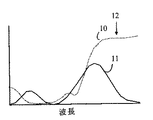
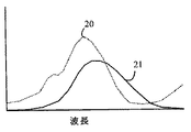
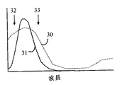
本発明はCIE1931標準に基づく表色系を参照することでより容易に理解することが出来る。しかしながら、以下の詳細説明からわかるように、本発明の原理は他の表色系にも適用することが可能である。ここで図1を参照するが、これは代表的な赤色素フィルタで得られる波長の関数としての色透過曲線が、CIE1931赤色プロファイルのカラープロファイルとどのように異なるかを示すものである。色素プロファイルは符号10に、CIE1931標準プロファイルは符号11に示した。図からわかるように、色素フィルタのカラープロファイルはCIE1931標準のものを著しく超える伸びを示している。同様に、青色及び緑色用に標準的に使用されている色素フィルタの色透過曲線も、図2及び図3に示したようにCIE1931標準の対応フィルタプロファイルよりも大幅に広い。図2は、代表的な緑色素フィルタで得られる波長の関数としての色透過曲線をCIE1931緑色プロファイルと比較したものである。色素プロファイルは符号20に示し、CIE1931標準プロファイルは符号21に示した。図3は青色素フィルタで得られる波長の関数としての色透過曲線をCIE1931青色プロファイルのカラープロファイルと比較したものである。色素プロファイルは符号30に示し、CIE1931標準プロファイルは符号31に示した。 The present invention can be more easily understood by referring to a color system based on the CIE 1931 standard. However, as will be appreciated from the detailed description below, the principles of the present invention can be applied to other color systems. Reference is now made to FIG. 1, which shows how the color transmission curve as a function of wavelength obtained with a typical red dye filter differs from the color profile of the CIE 1931 red profile. The dye profile is shown at 10 and the CIE 1931 standard profile is shown at 11. As can be seen, the color profile of the dye filter shows an elongation that is significantly greater than that of the CIE 1931 standard. Similarly, the color transmission curves of dye filters typically used for blue and green are also significantly wider than the corresponding filter profiles of the CIE 1931 standard, as shown in FIGS. FIG. 2 compares the color transmission curve as a function of wavelength obtained with a typical green dye filter with the CIE 1931 green profile. The dye profile is shown at 20 and the CIE 1931 standard profile is shown at 21. FIG. 3 compares the color transmission curve as a function of wavelength obtained with a blue dye filter with the color profile of the CIE 1931 blue profile. The dye profile is shown at 30 and the CIE 1931 standard profile is shown at 31.
本発明は、上述した色素フィルタを、これらの色素フィルタが対応する標準プロファイルを透過するように設計されたフィルタよりも大量の光を透過するスペクトル領域において、光を選択的に遮断する第2のフィルタと組み合わせることにより改良されたカラーフィルタを得ることが出来るという考えに基づいたものである。ここで図1に戻るが、赤色素フィルタは符号11に示す標準プロファイルを提供するフィルタよりも、符号12に示すスペクトル領域における光を大量に透過している。本発明は、この過剰に透過された光を除去する為の帯域遮断フィルタを用いている。赤色素フィルタの透過は
The present invention provides a second filter that selectively blocks light in the spectral region that transmits a greater amount of light than the filters described above that are designed to transmit the standard profile to which they correspond. This is based on the idea that an improved color filter can be obtained by combining with a filter. Returning now to FIG. 1, the red dye filter transmits more light in the spectral region indicated by
![]()
![]()
として、そして標準フィルタプロファイルを And the standard filter profile
![]()
![]()
として示す。この説明の目的上、これらのフィルタの最高透過率は同じものとする。この場合、理想的な帯域遮断フィルタは、以下に挙げる透過率を持っている。 As shown. For purposes of this description, the maximum transmittance of these filters is the same. In this case, an ideal band cut-off filter has the transmittance described below.
同様の帯域遮断フィルタを、最終的な複合フィルタが所望の標準フィルタに近いものに仕上がるように他の色素フィルタにも設けることが出来る。色素ベースのフィルタは、対応する色に対し、より理想的な標準透過曲線よりも大幅に広い透過曲線を持つ傾向がある。例えば、青色フィルタの透過曲線中で遮断すべき帯域位置を図3における符号32及び符号33で示した。一般に、色素フィルタ透過曲線を所望される透過曲線により近い透過曲線へと変換する為に希釈しなければならない色素フィルタ透過曲線帯域は、1帯域又は2帯域ある。
Similar band-stop filters can be provided for other dye filters so that the final composite filter is finished close to the desired standard filter. Dye-based filters tend to have a much broader transmission curve for the corresponding color than the more ideal standard transmission curve. For example, the band positions to be blocked in the transmission curve of the blue filter are indicated by
以下の説明を明確にする為に、上述した色素フィルタをプライマリカラーフィルタと呼び、帯域遮断フィルタをトリムフィルタと呼ぶものとする。本発明は、これらのトリムフィルタを遮断すべき帯域の各々において最低透過率を持つ単一の複合フィルタへと組み合わせることが出来るという考えを利用したものである。このようなフィルタを構築する方法を以下に詳細に説明する。この説明の便宜上、各トリムフィルタは、これが遮断する帯域以外のスペクトル領域においては、基本的に100%の透過率を持つものとして説明する。よってこのようなフィルタが複数積層された場合にも、遮断帯域と遮断帯域の間のスペクトル領域における透過率には基本的に変化は無い。従ってこのようなトリムフィルタのスタックを持つ単一の複合フィルタは、赤、緑及び青色素フィルタの上又は下に配置することが出来る。この結果、単一の色素フィルタよりも大幅に大きい物理寸法を持つトリムフィルタを利用することが出来、従って上述した寸法限界問題はより小さなものとなる。実際、単一の複合トリムフィルタは、何らかの形状パターニングをする場合でもわずかしか必要としない単一層としてカラーセンサアレイ全体の上又は下に配置することが出来るのである。 In order to clarify the following description, the above-described dye filter is referred to as a primary color filter, and the band cutoff filter is referred to as a trim filter. The present invention takes advantage of the idea that these trim filters can be combined into a single composite filter with the lowest transmission in each of the bands to be cut off. A method for constructing such a filter will be described in detail below. For convenience of explanation, each trim filter is basically assumed to have a transmittance of 100% in a spectral region other than the band that is cut off. Therefore, even when a plurality of such filters are stacked, there is basically no change in the transmittance in the spectral region between the stopband and the stopband. Thus, a single composite filter with such a stack of trim filters can be placed above or below the red, green and blue dye filters. As a result, a trim filter having a physical dimension that is significantly larger than that of a single dye filter can be utilized, thus making the dimensional limit problem described above smaller. In fact, a single composite trim filter can be placed above or below the entire color sensor array as a single layer that requires little if any shape patterning.
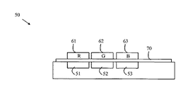
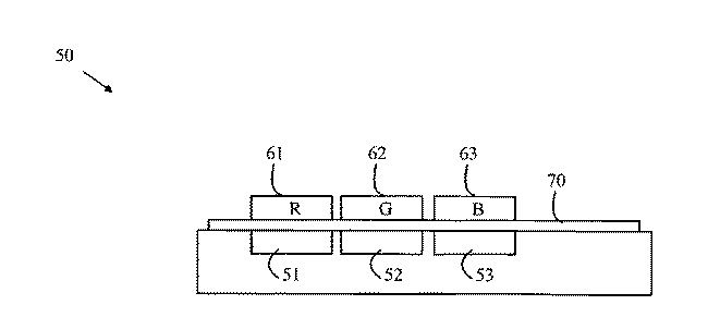
次に図4を参照するが、これは本発明の一実施例に基づくカラーセンサアレイの断面を描いたものである。カラーセンサ50は3つのフォトディテクタ51〜53を含む。各フォトディテクタは、対応する色素フィルタにより覆われている。フォトディテクタ51〜53に対応するフィルタは、それぞれ符号61〜63で示した。複合トリムフィルタ70は、色素フィルタの透過曲線を上述した方式と同様の方式で「切り取る」為に用いられる。トリムフィルタ70は、フォトディテクタと色素フィルタとの間に配置されることが望ましいが、色素フィルタ上にトリムフィルタを配置した実施例とすることも可能である。
Reference is now made to FIG. 4, which depicts a cross-section of a color sensor array according to one embodiment of the present invention. The
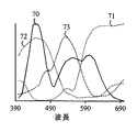
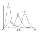
幾つかの代表的な色素フィルタとトリムフィルタの透過曲線を図5に示した。トリムフィルタの正規化された透過曲線は符号70に示し、赤、青、緑色素フィルタの正規化された透過曲線は、それぞれ符号71〜符号73に示した。フィルタの下にある赤色、青色及び緑色光を検出するフォトダイオードの応答曲線は、図6の符号81〜符号83にそれぞれ示した。この説明の便宜上、色素フィルタを、特定波長の光を選択的に吸収してそのフィルタ材料中の2つの原子又は分子エネルギー状態の間における遷移を誘発することにより、それを通過する光のカラースペクトルを変える何らかのフィルタと定義するものとする。従来のフォトリソグラフィー技術によりパターニングすることが出来る色素フィルタとしては、富士フィルム社製のものがある。
The transmission curves of some typical dye filters and trim filters are shown in FIG. The normalized transmission curve of the trim filter is indicated by
次にトリムフィルタを構成する方法を以下に詳細に説明する。推奨される帯域遮断フィルタは、厚さが均一な複数の透明層から構成された干渉フィルタであり、これらの層の隣接するもの同士は異なる屈折率を持っている。この種のフィルタは当該分野においては周知であり、本願においては、これらの詳細については説明しないものとする。説明の便宜上、このような層のスタックが、これらの層の厚さ及び屈折率により決まる波長の光を遮断するものであると述べるに留める。他の波長の光は遮断されない為、わずかに希釈されながらも層スタックを通過する。従ってこのような複数のフィルタを積層することにより、所定の波長群における各波長の光を遮断しつつも、所定波長群以外の波長の光は透過させる複合フィルタが提供されるのである。 Next, a method for configuring the trim filter will be described in detail below. The recommended band-cut filter is an interference filter composed of a plurality of transparent layers having a uniform thickness, and adjacent ones of these layers have different refractive indexes. This type of filter is well known in the art and will not be described in detail in this application. For convenience of explanation, it will be noted that such a stack of layers is intended to block light of a wavelength determined by the thickness and refractive index of these layers. Since other wavelengths of light are not blocked, they pass through the layer stack with slight dilution. Therefore, by laminating a plurality of such filters, a composite filter that transmits light of wavelengths other than the predetermined wavelength group while blocking light of each wavelength in the predetermined wavelength group is provided.
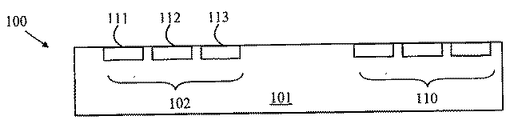
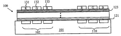
ここで図7〜図9を参照するが、これらは本発明の他の実施例に基づくカラーセンサアレイ100の様々な製造プロセス段階における断面図である。図7において、プロセスは基板101に複数のフォトダイオードを製作するステップから始まる。フォトダイオードセット例を符号102及び符号110に示した。フォトダイオードセットの各々は、符号111〜符号113に示した3つの別個のフォトダイオードを含んでいる。
Reference is now made to FIGS. 7-9, which are cross-sectional views at various manufacturing process stages of a
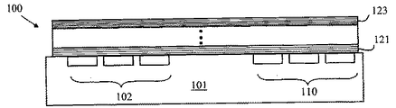
図8を見ると、基板101は堆積チャンバ中に入れられており、複合干渉フィルタの各層が基板表面に形成されている。干渉フィルタは当該分野においては周知である為、フィルタ構成の詳細についてはここでは説明しないものとする。遮断すべき2つの帯域に対応する層は符号121及び123に示した。層の様々な組成及び厚さは、各層に用いられる先駆物質組成及び堆積時間を調節することにより制御することが出来る為、基板を堆積処理中にチャンバから取り出す必要はない。従ってこの処理は経済的でもあり、歩留まりも高い。
Referring to FIG. 8, the
次に図9を参照するが、従来のフォトリソグラフィー技術により色素フィルタが帯域遮断フィルタ層の上に形成される。この実施例においては、赤色、青色及び緑色のスペクトル領域で透過性を持つ色素フィルタが使用されている。色素フィルタ例は符号131〜133に示した。
Referring now to FIG. 9, a dye filter is formed on the band-stop filter layer by conventional photolithography techniques. In this embodiment, dye filters that are transparent in the red, blue and green spectral regions are used. Examples of the dye filter are denoted by
上述した本発明の実施例は原色ろ波機能を得る為の色素フィルタと、色素フィルタの透過曲線端部を調節して目的とする透過関数に近いものを得る為の干渉フィルタを用いている。しかしながら、本発明はこれらのフィルタタイプの特定の組み合わせに限られたものではない。より広義に言えば、充分にパターニングし得るものであれば、これらの色素フィルタの代わりにどのようなフィルタ材料を使用しても良い。例えば、着色したフォトレジストを用いた色素フィルタを利用することも出来る。同様に、色素フィルタの透過曲線を変えて目的とするフィルタ機能に近づける為に1つ以上の色素フィルタ上に使用する帯域遮断フィルタも、どのような形式のものであっても良い。例えば、他の色素に基づく帯域通過フィルタを、それらの色素が異なる色素を利用する領域の作用に干渉する吸収帯を持たないものであれば利用することが出来る。 The above-described embodiments of the present invention use a dye filter for obtaining a primary color filtering function and an interference filter for obtaining an object close to the intended transmission function by adjusting the transmission curve end of the dye filter. However, the present invention is not limited to a specific combination of these filter types. In broader terms, any filter material may be used instead of these dye filters as long as they can be sufficiently patterned. For example, a dye filter using a colored photoresist can be used. Similarly, any type of band-cut filter used on one or more dye filters to change the transmission curve of the dye filter to approximate the desired filter function. For example, bandpass filters based on other dyes can be used as long as they do not have an absorption band that interferes with the action of regions that use different dyes.
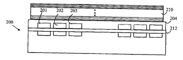
次に図10を参照するが、これは本発明に基づく他のカラーセンサの実施例を描いた断面図である。上述した実施例では色素フィルタが形成される前にトリムフィルタを設けるものであったが、色素フィルタ上にトリムフィルタを配置した構成の実施例も可能である。その形成に色素フィルタを損傷する恐れのある環境を要する材料からトリムフィルタが作られる場合、そしてトリムフィルタがフォトディテクタ上に形成すべきものである場合、トリムフィルタは先に設けられなければならない。しかしながら、トリムフィルタを別途形成し、色素フィルタ上にボンディングした、或いは取り付けた実施例も可能である。カラーセンサアレイ200は、緩衝層204を色素フィルタ201〜203上に設け、この緩衝層へとトリムフィルタ層210を被着することにより、色素フィルタ上に配置されたトリムフィルタを採用したものである。
Reference is now made to FIG. 10, which is a cross-sectional view depicting another color sensor embodiment in accordance with the present invention. In the above-described embodiment, the trim filter is provided before the dye filter is formed. However, an embodiment in which the trim filter is arranged on the dye filter is also possible. If the trim filter is made from an environmentally demanding material whose formation can damage the dye filter, and if the trim filter is to be formed on a photodetector, the trim filter must be provided first. However, an embodiment in which a trim filter is separately formed and bonded or mounted on a dye filter is also possible. The
加えて、トリムフィルタの一部分を色素フィルタの下に設け、第2の部分を色素フィルタの上に設けたトリムフィルタ構成も、特定の状況下にあっては有利に用いることが出来る。例えば、赤外線を除去するトリムフィルタは、様々な色素フィルタ構成において有用である。従って、このフィルタをフォトダイオード上に設けることにより、複数の異なるカラーセンサアレイを異なる色素フィルタ及び/又はトリムフィルタに基づいて構築する為の新たな出発基板とすることが出来る。このような下地フィルタは図10の符号212に示した。
In addition, a trim filter configuration in which a portion of the trim filter is provided below the dye filter and a second portion is provided above the dye filter can also be used advantageously under certain circumstances. For example, a trim filter that removes infrared light is useful in various dye filter configurations. Therefore, providing this filter on a photodiode can be a new starting substrate for building a plurality of different color sensor arrays based on different dye filters and / or trim filters. Such a base filter is denoted by
先に式1に示した理想的なトリムフィルタは推奨されるものではあるが、より理想から離れた他のトリムフィルタを利用しても相当な利益を得ることが出来る。概して本発明は、トリムフィルタと色素フィルタの組み合わせが、色素フィルタのみとした場合の透過曲線よりも目的とするフィルタ機能に近い透過曲線を提供するものであった場合に利点を提供するものであると言える。 Although the ideal trim filter previously shown in Equation 1 is recommended, significant benefits can be obtained using other trim filters that are more distant from the ideal. In general, the present invention provides an advantage when the combination of a trim filter and a dye filter provides a transmission curve that is closer to the desired filter function than the transmission curve of the dye filter alone. It can be said.
上述した本発明の実施例は、CIE1931標準のフィルタを使って説明したものである。しかしながら、本発明の原理は、他のフィルタ標準を利用したカラーセンサアレイの製作にも適用することが出来る。更に、カラーセンサ中の色素フィルタの数は3つとは限らない。 The above-described embodiment of the present invention has been described using a CIE 1931 standard filter. However, the principles of the present invention can also be applied to the fabrication of color sensor arrays using other filter standards. Furthermore, the number of dye filters in the color sensor is not limited to three.
上述したように、理想的なトリムフィルタは、遮断帯域と遮断帯域の間にある波長を持つ光を吸収しない帯域遮断フィルタを利用したものである。しかしながら、これらの領域における若干の吸収は許容範囲に入るものであることに留意が必要である。トリムフィルタの遮断帯域間の透過曲線が実質的に一定である場合、吸収があったとしても対象となるカラーセンサのフォトディテクタの利得を調節することにより修正することが出来る。 As described above, an ideal trim filter uses a band cutoff filter that does not absorb light having a wavelength between the cutoff band and the cutoff band. However, it should be noted that some absorption in these areas is acceptable. If the transmission curve between the cutoff bands of the trim filter is substantially constant, even if there is absorption, it can be corrected by adjusting the gain of the photodetector of the target color sensor.
上述した本発明の実施例では、フォトディテクタにフォトダイオードを利用したものである。しかしながら、入射した光の強度に関する信号を生成するものであれば、いずれの形態のフォトディテクタを利用しても良い。例えば、上述したフォトダイオードに代えてフォトトランジスタ及びCCDとすることも可能である。 In the embodiment of the present invention described above, a photodiode is used as a photodetector. However, any type of photodetector may be used as long as it generates a signal relating to the intensity of incident light. For example, a phototransistor and a CCD may be used instead of the photodiode described above.
上述の実施形態に即して本発明を説明すると、本発明は、光源からの光を測定する為のカラーセンサ(50、200)であって、複数のフォトディテクタ(51〜53)と、各々が前記光源と前記フォトディテクタ(51〜53)のうちの対応する1つとの間に材料層を含み、各々が特性波長付近の対応する波長帯域にある光を選択的に透過する複数のプライマリカラーフィルタ(61〜63)と、前記光源と前記フォトディテクタ(51〜53)の間に位置し、2つの前記特性波長の間にある第1のトリム波長の光を選択的に減衰させる材料層を含む第1のトリムフィルタ(70、210)とを具備したことを特徴とするカラーセンサを提供する。 The present invention will be described in accordance with the above-described embodiment. The present invention is a color sensor (50, 200) for measuring light from a light source, and includes a plurality of photodetectors (51-53), A plurality of primary color filters including a material layer between the light source and the corresponding one of the photodetectors (51 to 53), each selectively transmitting light in the corresponding wavelength band near the characteristic wavelength. 61-63), and a first material layer that is located between the light source and the photodetector (51-53) and includes a material layer that selectively attenuates light having a first trim wavelength between the two characteristic wavelengths. And a trim sensor (70, 210).
好ましくは、前記第1のトリムフィルタ(70、210)は、更に第2のトリム波長の光を選択的に減衰させるものであり、前記第1のトリム波長が前記特性波長の1つよりも小さく、前記第2のトリム波長がその前記特性波長よりも大きいものとされる。 Preferably, the first trim filter (70, 210) further selectively attenuates light of the second trim wavelength, and the first trim wavelength is smaller than one of the characteristic wavelengths. The second trim wavelength is larger than the characteristic wavelength.
好ましくは、前記第1のトリムフィルタ(70、210)は、干渉フィルタを含む。 Preferably, the first trim filter (70, 210) includes an interference filter.
好ましくは、前記フォトディテクタ(102、110)を設けた基板(101)を更に具備し、前記第1のトリムフィルタ(210)は、前記基板(101)上に第1のトリムフィルタ層(123)を含む。 Preferably, a substrate (101) provided with the photodetectors (102, 110) is further provided, and the first trim filter (210) includes a first trim filter layer (123) on the substrate (101). Including.
好ましくは、前記カラーフィルタ(131〜133)は、前記第1のトリムフィルタ層(123)上に位置する。 Preferably, the color filters (131 to 133) are located on the first trim filter layer (123).
好ましくは、前記カラーフィルタ(201〜203)は、前記第1のトリムフィルタ(210)と前記フォトディテクタ(51〜53)の間に位置する。 Preferably, the color filter (201 to 203) is located between the first trim filter (210) and the photodetector (51 to 53).
好ましくは、第2のトリムフィルタ(212)を更に具備し、前記第2のトリムフィルタ(212)は、前記特性波長及び前記第1のトリム波長のそれぞれとは異なる第2の波長の光を選択的に減衰させる材料層を含む。 Preferably, the apparatus further includes a second trim filter (212), and the second trim filter (212) selects light having a second wavelength different from each of the characteristic wavelength and the first trim wavelength. A layer of attenuating material.
好ましくは、前記カラーフィルタ(201〜203)は、前記第1及び第2のトリムフィルタ(210、212)の間に位置する。 Preferably, the color filter (201 to 203) is located between the first and second trim filters (210, 212).
さらに、本発明は、カラーセンサ(50、200)を製作する為の方法であって、複数のフォトディテクタ(51〜53)を持つ基板(101)を設けるステップと、第1のトリムフィルタ層(123)を前記基板(101)へと被着するステップと、前記第1のトリムフィルタ層(123)へと複数のプライマリカラーフィルタ(61〜63)を含むカラーフィルタ層を被着するステップとを有し、前記プライマリカラーフィルタの各々が前記光源と前記フォトディテクタ(51〜53)の対応する1つとの間に材料層を含み、前記プライマリカラーフィルタの各々が特性波長付近の対応する波長帯域にある光を選択的に透過するものであり、前記第1のトリムフィルタ(70、210)が2つの前記特性波長の間にある第1のトリム波長の光を減衰させるものであることを特徴とする方法を提供する。 Further, the present invention is a method for manufacturing a color sensor (50, 200), the step of providing a substrate (101) having a plurality of photodetectors (51-53), and a first trim filter layer (123). ) To the substrate (101), and to the first trim filter layer (123) a color filter layer including a plurality of primary color filters (61 to 63). And each of the primary color filters includes a material layer between the light source and the corresponding one of the photodetectors (51-53), and each of the primary color filters is in a corresponding wavelength band near a characteristic wavelength. A first trim wavelength, wherein the first trim filter (70, 210) is between the two characteristic wavelengths. A method which is characterized in that one which attenuates light.
好ましくは、前記第1のトリムフィルタ(70、210)は、更に第2のトリム波長の光を減衰させるものであり、前記第1の波長が前記特性波長の1つよりも小さく、前記第2の波長がその前記特性波長よりも大きいものとされる。 Preferably, the first trim filter (70, 210) further attenuates light of a second trim wavelength, and the first wavelength is smaller than one of the characteristic wavelengths, Is larger than the characteristic wavelength.
好ましくは、前記第1のトリムフィルタ(70、210)は、複数の透明層を含み、その中の隣接する層が異なる屈折率を持つ。 Preferably, the first trim filter (70, 210) includes a plurality of transparent layers, in which adjacent layers have different refractive indexes.
好ましくは、第2のトリムフィルタ層(212)を前記カラーフィルタ層へと被着することにより、前記カラーフィルタ層が前記第1及び第2のトリムフィルタ層(210、212)の間に挟まれるようにするステップを更に含む。 Preferably, the color filter layer is sandwiched between the first and second trim filter layers (210, 212) by applying a second trim filter layer (212) to the color filter layer. The method further includes the step of:
上述した説明及び添付図から、本発明に様々な変更が可能であることは当業者であれば明らかである。よって本発明は、本願請求項の範囲によってのみ限定されるものである。 It will be apparent to those skilled in the art from the foregoing description and accompanying drawings that various modifications can be made to the present invention. Therefore, the present invention is limited only by the scope of the claims.
50、200 カラーセンサ
51〜53 フォトディテクタ
61〜63 プライマリカラーフィルタ
70、210 第1のトリムフィルタ
101 基板
102、110 フォトディテクタ
123 第1のトリムフィルタ層
201〜203 プライマリカラーフィルタ
210 第1のトリムフィルタ
212 第2のトリムフィルタ
50, 200 Color sensor 51-53 Photo detector 61-63
Claims (12)
複数のフォトディテクタと、
各々が前記光源と前記フォトディテクタのうちの対応する1つとの間に材料層を含み、各々が特性波長付近の対応する波長帯域にある光を選択的に透過する複数のプライマリカラーフィルタと、
前記光源と前記フォトディテクタの間に位置し、2つの前記特性波長の間にある第1のトリム波長の光を選択的に減衰させる材料層を含む第1のトリムフィルタとを具備したことを特徴とするカラーセンサ。 A color sensor for measuring light from a light source,
Multiple photo detectors,
A plurality of primary color filters each including a material layer between the light source and a corresponding one of the photodetectors, each selectively transmitting light in a corresponding wavelength band near a characteristic wavelength;
A first trim filter located between the light source and the photodetector and including a material layer that selectively attenuates light having a first trim wavelength between the two characteristic wavelengths; Color sensor.
Applying a second trim filter layer to the color filter layer so that the color filter layer is sandwiched between the first and second trim filter layers. The method according to claim 9.
Applications Claiming Priority (2)
| Application Number | Priority Date | Filing Date | Title |
|---|---|---|---|
| US10/804,272 US7285768B2 (en) | 2004-03-18 | 2004-03-18 | Color photodetector array |
| US804272 | 2004-03-18 |
Publications (3)
| Publication Number | Publication Date |
|---|---|
| JP2005294825A true JP2005294825A (en) | 2005-10-20 |
| JP2005294825A5 JP2005294825A5 (en) | 2008-04-24 |
| JP4899008B2 JP4899008B2 (en) | 2012-03-21 |
Family
ID=34985244
Family Applications (1)
| Application Number | Title | Priority Date | Filing Date |
|---|---|---|---|
| JP2005076762A Expired - Lifetime JP4899008B2 (en) | 2004-03-18 | 2005-03-17 | Improved color photodetector array and method of manufacturing the same |
Country Status (3)
| Country | Link |
|---|---|
| US (1) | US7285768B2 (en) |
| JP (1) | JP4899008B2 (en) |
| CN (1) | CN1670493B (en) |
Cited By (3)
| Publication number | Priority date | Publication date | Assignee | Title |
|---|---|---|---|---|
| JP2007311664A (en) * | 2006-05-19 | 2007-11-29 | Sharp Corp | COLOR SENSOR, COLOR SENSOR MANUFACTURING METHOD, SENSOR, AND ELECTRONIC DEVICE |
| JP2008070437A (en) * | 2006-09-12 | 2008-03-27 | Matsushita Electric Ind Co Ltd | Interference filter, liquid crystal display, electroluminescence display, projection display device |
| JP2012038938A (en) * | 2010-08-06 | 2012-02-23 | Canon Inc | Solid state image sensor and camera |
Families Citing this family (15)
| Publication number | Priority date | Publication date | Assignee | Title |
|---|---|---|---|---|
| EP1812782A4 (en) * | 2004-11-16 | 2010-04-07 | Datacolor Holding Ag | Method for designing a colorimeter having integral cie color-matching filters |
| US7593105B2 (en) * | 2004-11-17 | 2009-09-22 | Datacolor Holding Ag | Tristimulus colorimeter having integral dye filters |
| US7580130B2 (en) * | 2005-03-23 | 2009-08-25 | Datacolor Holding Ag | Method for designing a colorimeter having integral illuminant-weighted CIE color-matching filters |
| US7474402B2 (en) * | 2005-03-23 | 2009-01-06 | Datacolor Holding Ag | Reflectance sensor for integral illuminant-weighted CIE color matching filters |
| US20070152139A1 (en) * | 2005-12-30 | 2007-07-05 | Moores Mark D | Techniques to control illumination for image sensors |
| JP5008017B2 (en) * | 2006-02-10 | 2012-08-22 | ソニーモバイルディスプレイ株式会社 | Display device |
| JP2007220832A (en) * | 2006-02-15 | 2007-08-30 | Matsushita Electric Ind Co Ltd | Solid-state imaging device and camera |
| US7649220B2 (en) * | 2007-03-29 | 2010-01-19 | Avago Technologies Ecbu Ip (Singapore) Pte. Ltd. | Photodetector having dark current correction |
| US7435943B1 (en) * | 2007-03-29 | 2008-10-14 | Avago Technologies Ecbu Ip Pte Ltd | Color sensor with infrared correction having a filter layer blocking a portion of light of visible spectrum |
| JP5038011B2 (en) * | 2007-04-25 | 2012-10-03 | キヤノン株式会社 | Information processing method, information processing apparatus, and recording medium |
| US20100208266A1 (en) * | 2009-02-17 | 2010-08-19 | Colman Shannon | Tristimulus colorimeter having integral dye filters |
| JP6315759B2 (en) * | 2013-10-11 | 2018-04-25 | シャープ株式会社 | Fluorescence detection device and vacuum cleaner |
| CN105628190B (en) * | 2014-10-30 | 2017-12-22 | 杭州远方光电信息股份有限公司 | A kind of optical radiation measurement method and its device based on filter unit |
| EP3450938B1 (en) * | 2017-08-30 | 2022-10-12 | IMEC vzw | An image sensor and an imaging apparatus |
| CN116773020A (en) * | 2022-03-10 | 2023-09-19 | 光宝科技股份有限公司 | Color sensor, color sensing device and method thereof |
Citations (6)
| Publication number | Priority date | Publication date | Assignee | Title |
|---|---|---|---|---|
| JPS5619288A (en) * | 1979-07-26 | 1981-02-23 | Dainippon Printing Co Ltd | Color solid state image pickup element plate |
| JPS57184937A (en) * | 1981-05-08 | 1982-11-13 | Omron Tateisi Electronics Co | Color discriminating element |
| JPS6298965A (en) * | 1985-10-25 | 1987-05-08 | Canon Inc | Original reading device |
| JPH01154102A (en) * | 1987-12-11 | 1989-06-16 | Fuji Photo Film Co Ltd | Interference filter |
| JPH01246508A (en) * | 1988-03-29 | 1989-10-02 | Konica Corp | Color separation filter device |
| JPH07170366A (en) * | 1993-10-22 | 1995-07-04 | Canon Inc | Image sensor filter, image sensor and image information processing device |
Family Cites Families (3)
| Publication number | Priority date | Publication date | Assignee | Title |
|---|---|---|---|---|
| US3996461A (en) * | 1975-03-31 | 1976-12-07 | Texas Instruments Incorporated | Silicon photosensor with optical thin film filter |
| US5073008A (en) * | 1987-12-11 | 1991-12-17 | Fuji Photo Film Co., Ltd. | Multicolor interference filters with side surfaces to prevent entry of undesirable light |
| US5648653A (en) * | 1993-10-22 | 1997-07-15 | Canon Kabushiki Kaisha | Optical filter having alternately laminated thin layers provided on a light receiving surface of an image sensor |
-
2004
- 2004-03-18 US US10/804,272 patent/US7285768B2/en not_active Expired - Lifetime
-
2005
- 2005-03-17 JP JP2005076762A patent/JP4899008B2/en not_active Expired - Lifetime
- 2005-03-18 CN CN2005100554677A patent/CN1670493B/en not_active Expired - Lifetime
Patent Citations (6)
| Publication number | Priority date | Publication date | Assignee | Title |
|---|---|---|---|---|
| JPS5619288A (en) * | 1979-07-26 | 1981-02-23 | Dainippon Printing Co Ltd | Color solid state image pickup element plate |
| JPS57184937A (en) * | 1981-05-08 | 1982-11-13 | Omron Tateisi Electronics Co | Color discriminating element |
| JPS6298965A (en) * | 1985-10-25 | 1987-05-08 | Canon Inc | Original reading device |
| JPH01154102A (en) * | 1987-12-11 | 1989-06-16 | Fuji Photo Film Co Ltd | Interference filter |
| JPH01246508A (en) * | 1988-03-29 | 1989-10-02 | Konica Corp | Color separation filter device |
| JPH07170366A (en) * | 1993-10-22 | 1995-07-04 | Canon Inc | Image sensor filter, image sensor and image information processing device |
Cited By (4)
| Publication number | Priority date | Publication date | Assignee | Title |
|---|---|---|---|---|
| JP2007311664A (en) * | 2006-05-19 | 2007-11-29 | Sharp Corp | COLOR SENSOR, COLOR SENSOR MANUFACTURING METHOD, SENSOR, AND ELECTRONIC DEVICE |
| US7605354B2 (en) | 2006-05-19 | 2009-10-20 | Sharp Kabushiki Kaisha | Color sensor, production method thereof, sensor, and electronics device |
| JP2008070437A (en) * | 2006-09-12 | 2008-03-27 | Matsushita Electric Ind Co Ltd | Interference filter, liquid crystal display, electroluminescence display, projection display device |
| JP2012038938A (en) * | 2010-08-06 | 2012-02-23 | Canon Inc | Solid state image sensor and camera |
Also Published As
| Publication number | Publication date |
|---|---|
| CN1670493A (en) | 2005-09-21 |
| US7285768B2 (en) | 2007-10-23 |
| US20050205765A1 (en) | 2005-09-22 |
| JP4899008B2 (en) | 2012-03-21 |
| CN1670493B (en) | 2010-12-22 |
Similar Documents
| Publication | Publication Date | Title |
|---|---|---|
| JP4899008B2 (en) | Improved color photodetector array and method of manufacturing the same | |
| US8227883B2 (en) | Solid-state imaging device and camera | |
| JP6410203B1 (en) | Solid-state imaging device and imaging apparatus | |
| EP3771892B1 (en) | Optical filter and spectrometer including the same | |
| US7858921B2 (en) | Guided-mode-resonance transmission color filters for color generation in CMOS image sensors | |
| TWI628470B (en) | Multi-color filter with low color error and high signal-to-noise ratio | |
| TW200524150A (en) | Solid state imaging device, process for fabricating solid state imaging device and camera employing same | |
| EP3450938B1 (en) | An image sensor and an imaging apparatus | |
| JP2012019113A (en) | Solid-state imaging device | |
| JP2000151933A (en) | Image pickup element and its manufacture | |
| JP2010212306A (en) | Solid-state image device | |
| CN114335038B (en) | Image sensors with improved color accuracy | |
| JP2023010673A (en) | Multi-bandpass optical interference filter | |
| JP2007013188A (en) | Color image sensor | |
| JP2000180621A (en) | On-chip color filter and solid-state imaging device using the same | |
| JP2005266811A (en) | Color filter and manufacturing method thereof | |
| WO2021161961A1 (en) | Optical filter and production method therefor, optical sensor, and solid-state imaging element | |
| JPH02166767A (en) | Color solid state image sensor and manufacture thereof | |
| KR100700264B1 (en) | Color filter formation method of image sensor | |
| JP4984528B2 (en) | Imaging device | |
| HK40046352A (en) | Optical filter and spectrometer including the same | |
| JP2005093659A (en) | Solid-state image sensor | |
| HK40046352B (en) | Optical filter and spectrometer including the same | |
| JP2022069852A (en) | Multi-color sensor and multi-color sensor device | |
| JP2008153308A (en) | Solid-state image sensing device and camera |
Legal Events
| Date | Code | Title | Description |
|---|---|---|---|
| RD03 | Notification of appointment of power of attorney |
Free format text: JAPANESE INTERMEDIATE CODE: A7423 Effective date: 20060412 |
|
| A711 | Notification of change in applicant |
Free format text: JAPANESE INTERMEDIATE CODE: A711 Effective date: 20070326 |
|
| A521 | Request for written amendment filed |
Free format text: JAPANESE INTERMEDIATE CODE: A523 Effective date: 20080311 |
|
| A621 | Written request for application examination |
Free format text: JAPANESE INTERMEDIATE CODE: A621 Effective date: 20080311 |
|
| A131 | Notification of reasons for refusal |
Free format text: JAPANESE INTERMEDIATE CODE: A131 Effective date: 20110607 |
|
| A977 | Report on retrieval |
Free format text: JAPANESE INTERMEDIATE CODE: A971007 Effective date: 20110609 |
|
| A521 | Request for written amendment filed |
Free format text: JAPANESE INTERMEDIATE CODE: A523 Effective date: 20110830 |
|
| A131 | Notification of reasons for refusal |
Free format text: JAPANESE INTERMEDIATE CODE: A131 Effective date: 20110920 |
|
| A521 | Request for written amendment filed |
Free format text: JAPANESE INTERMEDIATE CODE: A523 Effective date: 20111104 |
|
| TRDD | Decision of grant or rejection written | ||
| A01 | Written decision to grant a patent or to grant a registration (utility model) |
Free format text: JAPANESE INTERMEDIATE CODE: A01 Effective date: 20111122 |
|
| A711 | Notification of change in applicant |
Free format text: JAPANESE INTERMEDIATE CODE: A711 Effective date: 20111129 |
|
| A01 | Written decision to grant a patent or to grant a registration (utility model) |
Free format text: JAPANESE INTERMEDIATE CODE: A01 |
|
| A61 | First payment of annual fees (during grant procedure) |
Free format text: JAPANESE INTERMEDIATE CODE: A61 Effective date: 20111201 |
|
| R150 | Certificate of patent or registration of utility model |
Ref document number: 4899008 Country of ref document: JP Free format text: JAPANESE INTERMEDIATE CODE: R150 Free format text: JAPANESE INTERMEDIATE CODE: R150 |
|
| FPAY | Renewal fee payment (event date is renewal date of database) |
Free format text: PAYMENT UNTIL: 20150113 Year of fee payment: 3 |
|
| R250 | Receipt of annual fees |
Free format text: JAPANESE INTERMEDIATE CODE: R250 |
|
| R250 | Receipt of annual fees |
Free format text: JAPANESE INTERMEDIATE CODE: R250 |
|
| R250 | Receipt of annual fees |
Free format text: JAPANESE INTERMEDIATE CODE: R250 |
|
| R250 | Receipt of annual fees |
Free format text: JAPANESE INTERMEDIATE CODE: R250 |
|
| R250 | Receipt of annual fees |
Free format text: JAPANESE INTERMEDIATE CODE: R250 |
|
| R250 | Receipt of annual fees |
Free format text: JAPANESE INTERMEDIATE CODE: R250 |
|
| R250 | Receipt of annual fees |
Free format text: JAPANESE INTERMEDIATE CODE: R250 |
|
| R250 | Receipt of annual fees |
Free format text: JAPANESE INTERMEDIATE CODE: R250 |
|
| R250 | Receipt of annual fees |
Free format text: JAPANESE INTERMEDIATE CODE: R250 |
|
| R250 | Receipt of annual fees |
Free format text: JAPANESE INTERMEDIATE CODE: R250 |
|
| R250 | Receipt of annual fees |
Free format text: JAPANESE INTERMEDIATE CODE: R250 |
|
| EXPY | Cancellation because of completion of term |