JP2005266811A - Color filter and its manufacturing method - Google Patents
Color filter and its manufacturing method Download PDFInfo
- Publication number
- JP2005266811A JP2005266811A JP2005076882A JP2005076882A JP2005266811A JP 2005266811 A JP2005266811 A JP 2005266811A JP 2005076882 A JP2005076882 A JP 2005076882A JP 2005076882 A JP2005076882 A JP 2005076882A JP 2005266811 A JP2005266811 A JP 2005266811A
- Authority
- JP
- Japan
- Prior art keywords
- filter
- wavelength
- trim
- color
- characteristic
- Prior art date
- Legal status (The legal status is an assumption and is not a legal conclusion. Google has not performed a legal analysis and makes no representation as to the accuracy of the status listed.)
- Withdrawn
Links
- 238000004519 manufacturing process Methods 0.000 title abstract description 11
- 230000005540 biological transmission Effects 0.000 claims abstract description 53
- 239000000463 material Substances 0.000 claims abstract description 15
- 238000000034 method Methods 0.000 claims description 16
- 238000000151 deposition Methods 0.000 claims description 8
- 239000000758 substrate Substances 0.000 claims description 7
- 238000004040 coloring Methods 0.000 claims description 5
- 238000009966 trimming Methods 0.000 abstract 2
- 239000010410 layer Substances 0.000 description 54
- 239000000975 dye Substances 0.000 description 52
- 230000003595 spectral effect Effects 0.000 description 8
- 239000002131 composite material Substances 0.000 description 7
- 239000001044 red dye Substances 0.000 description 6
- 238000001228 spectrum Methods 0.000 description 5
- 238000003491 array Methods 0.000 description 4
- 239000001045 blue dye Substances 0.000 description 4
- 239000001046 green dye Substances 0.000 description 4
- 238000005259 measurement Methods 0.000 description 4
- 238000002834 transmittance Methods 0.000 description 4
- 238000010521 absorption reaction Methods 0.000 description 3
- 230000008901 benefit Effects 0.000 description 3
- 230000008859 change Effects 0.000 description 3
- 230000008569 process Effects 0.000 description 3
- 230000035945 sensitivity Effects 0.000 description 3
- 230000000903 blocking effect Effects 0.000 description 2
- 230000008021 deposition Effects 0.000 description 2
- 239000000203 mixture Substances 0.000 description 2
- 238000000059 patterning Methods 0.000 description 2
- 238000000206 photolithography Methods 0.000 description 2
- 230000004044 response Effects 0.000 description 2
- 241000282412 Homo Species 0.000 description 1
- 235000010724 Wisteria floribunda Nutrition 0.000 description 1
- 230000009471 action Effects 0.000 description 1
- 230000015572 biosynthetic process Effects 0.000 description 1
- 239000003086 colorant Substances 0.000 description 1
- 238000005137 deposition process Methods 0.000 description 1
- 238000010790 dilution Methods 0.000 description 1
- 239000012895 dilution Substances 0.000 description 1
- 239000010408 film Substances 0.000 description 1
- 238000001914 filtration Methods 0.000 description 1
- 238000010030 laminating Methods 0.000 description 1
- 238000012986 modification Methods 0.000 description 1
- 230000004048 modification Effects 0.000 description 1
- 229920002120 photoresistant polymer Polymers 0.000 description 1
- 239000002243 precursor Substances 0.000 description 1
- 239000002356 single layer Substances 0.000 description 1
- 239000010409 thin film Substances 0.000 description 1
- 230000007704 transition Effects 0.000 description 1
Images


Classifications
-
- G—PHYSICS
- G02—OPTICS
- G02B—OPTICAL ELEMENTS, SYSTEMS OR APPARATUS
- G02B5/00—Optical elements other than lenses
- G02B5/20—Filters
- G02B5/201—Filters in the form of arrays
-
- Y—GENERAL TAGGING OF NEW TECHNOLOGICAL DEVELOPMENTS; GENERAL TAGGING OF CROSS-SECTIONAL TECHNOLOGIES SPANNING OVER SEVERAL SECTIONS OF THE IPC; TECHNICAL SUBJECTS COVERED BY FORMER USPC CROSS-REFERENCE ART COLLECTIONS [XRACs] AND DIGESTS
- Y10—TECHNICAL SUBJECTS COVERED BY FORMER USPC
- Y10T—TECHNICAL SUBJECTS COVERED BY FORMER US CLASSIFICATION
- Y10T156/00—Adhesive bonding and miscellaneous chemical manufacture
- Y10T156/10—Methods of surface bonding and/or assembly therefor
Abstract
Description
本発明はフィルタ上の空間的位置によって変化するカラーフィルタ通過帯域に関するものである。 The present invention relates to a color filter passband that varies with the spatial position on the filter.
本発明は、画像記録用にフォトダイオードのカラーセンサアレイを用いたカメラを例にとると理解し易い。色の感度を得る上で、一般にフォトダイオードはそれぞれに赤色、緑色及び青色光を検出する3つのフォトダイオードクラスに分けられる。各種の色感度を持つこれらのダイオードは、アレイ中に分散配置される。例えば、ディテクタアレイには、各画素が赤色光測定用、緑色光測定用及び青色光測定用の3つのフォトダイオードを含むことを特徴とする画素アレイから成るものがある。 The present invention can be easily understood by taking as an example a camera using a color sensor array of photodiodes for image recording. In order to obtain color sensitivity, photodiodes are generally divided into three photodiode classes that detect red, green and blue light respectively. These diodes with various color sensitivities are distributed in the array. For example, some detector arrays comprise a pixel array in which each pixel includes three photodiodes for red light measurement, green light measurement, and blue light measurement.
カラーセンサは一般に、特定の色通過帯域を選択する透過フィルタを同じフォトダイオードを並べたアレイ上に設けることにより作られる。即ち、カメラチップは色感度をほぼ持たないフォトディテクタのアレイ上に、空間的位置によって変化する通過帯域を持つフィルタを用いたものと見ることが出来る。フィルタは、赤色、青色及び緑色の範囲に及ぶ広いスペクトル範囲の光に感度を持つフォトダイオード上に設けられる色素フィルタから構成されることが一般的である。例えば、カラーカメラアレイは、従来のフォトリソグラフィー技術を用い、アレイ中の各ダイオード上に選択的に対象となる色素を設けることにより赤色、青色又は緑色フィルタをパターンニングして製作することが可能である。しかしながら、このプロセスには色素フィルタに用いることが出来る材料による制約がある。従って作ることが出来るカラーフィルタ・プロファイルには制約がある。例えば、これらのフィルタは赤外線(IR)光を遮断することが出来ない為、このようなカメラには更にIR遮断フィルタを設けなければならず、カメラのコストが増大してしまうのである。 Color sensors are typically made by providing a transmission filter that selects a particular color passband on an array of the same photodiodes. In other words, the camera chip can be regarded as using a filter having a pass band that varies depending on the spatial position on an array of photodetectors having almost no color sensitivity. The filter is typically composed of a dye filter provided on a photodiode that is sensitive to light in a wide spectral range ranging from red, blue and green. For example, a color camera array can be fabricated using conventional photolithographic techniques and patterning red, blue, or green filters by selectively providing a target dye on each diode in the array. is there. However, this process is limited by the materials that can be used for the dye filter. Therefore, there are restrictions on the color filter profiles that can be created. For example, since these filters cannot block infrared (IR) light, such cameras must be further provided with an IR blocking filter, which increases the cost of the camera.
加えて、あらかじめ特定したカラープロファイルを作ることは困難である。一般に設計者は、設計者が制御し得ない透過曲線を持つ1つ以上のフィルタを使用しなければならない。例えば、色素フィルタから得られるフィルタプロファイルは、各画素について人が見て感知する色の特定に用いられる標準フィルタプロファイルと一致しない。光源の色を人が目視する為にプリンタで再生する場合のアプリケーションを想定したい。光源は非常に複雑なスペクトルを持っているが、人の目は光源を3つの色源から色を組み合わせて再生することが出来る単一色を持つものとして認識する。プリンタは、CIE1931標準等の何らかの標準表色系を使って校正される。RGB値が標準表色系におけるRGBスペクトルパターンを持つ光の強度を表すものである場合、プリンタは適正な色を生成する。即ち、用紙に記録される光のスペクトルは光源のものとは異なってはいるものの、人の目は光源と同じ色が用紙に印刷されているものと認識するのである。 In addition, it is difficult to create a color profile specified in advance. In general, the designer must use one or more filters with transmission curves that the designer cannot control. For example, the filter profile obtained from the dye filter does not match the standard filter profile used to identify the color that humans see and perceive for each pixel. Imagine an application in which the color of a light source is reproduced by a printer so that a person can see it. Although the light source has a very complex spectrum, the human eye perceives the light source as having a single color that can be reproduced by combining colors from three color sources. The printer is calibrated using some standard color system, such as the CIE 1931 standard. If the RGB value represents the intensity of light having an RGB spectral pattern in the standard color system, the printer generates the proper color. That is, although the spectrum of light recorded on the paper is different from that of the light source, the human eye recognizes that the same color as the light source is printed on the paper.
色素フィルタを用いたセンサにより測定されるRGB値は、色素フィルタの透過曲線により決まる加重波長帯域で光の強度を測ったものである。色素フィルタを使ったフォトディテクタから測定された強度をR’、G’、B’として説明する。一般に、このR’G’B’はフィルタ重み関数が異なる為に、標準向けの理想的なフィルタにより得られるRGB値とは異なる。よってこの色素ベースの値がプリンタへと送られた場合、プリンタはカラーセンサへと入力された光とは異なる色を生成することになる。 The RGB value measured by the sensor using the dye filter is obtained by measuring the light intensity in the weighted wavelength band determined by the transmission curve of the dye filter. The intensity measured from the photodetector using the dye filter will be described as R ′, G ′, and B ′. In general, this R'G'B 'is different from the RGB value obtained by an ideal filter for a standard because the filter weight function is different. Thus, when this dye-based value is sent to the printer, the printer will produce a color that is different from the light input to the color sensor.
干渉技術を利用すればより望ましいカラープロファイルを持つフィルタを製作することが出来るが、これらのフィルタを面積の小さなフォトダイオード上に作ることは困難である。よってこれらのフィルタは画素寸法が非常に小さくなければならないカラーカメラ等への使用には適していないのである。干渉フィルタは、異なる屈折率を持つ複数の透明誘電体薄膜を設けることにより作られる。波長とフィルタプロファイルは誘電体の厚さ及び屈折率を変えることにより設定される。これによりフィルタプロファイル・デザインには大きな柔軟性が提供される。しかしながら、この技術では高解像度カメラ用の個々の画素をパターニングすることが困難である為、CCDカメラチップには適していない。従ってカメラに干渉フィルタを用いるには、3つの別個のチップ上に3つの別個のアレイを必要とするのである。各チップは1色の光の画像を検出する。次に3つのモノクロ画像が組み合わせられ、最終的なカラー画像が作られる。各チップは一種類のフィルタしか必要としないことから、フォトダイオード・サイズの小型フィルタを個々に作るという問題は回避される。しかしながら、カメラチップを別個に3つも必要とすることからコストとカメラの光学系の複雑性が増大する。加えて、各チップが使える光の強度は3分の1に低下することから、色計測を行う為に必要な光の量が増大する。 Although interference filters can be used to produce filters with more desirable color profiles, it is difficult to make these filters on small area photodiodes. Therefore, these filters are not suitable for use in a color camera or the like whose pixel size must be very small. The interference filter is made by providing a plurality of transparent dielectric thin films having different refractive indexes. The wavelength and filter profile are set by changing the dielectric thickness and refractive index. This provides great flexibility for the filter profile design. However, this technique is not suitable for a CCD camera chip because it is difficult to pattern individual pixels for a high-resolution camera. Thus, using an interference filter in a camera requires three separate arrays on three separate chips. Each chip detects an image of one color light. The three monochrome images are then combined to create the final color image. Since each chip requires only one type of filter, the problem of making small photodiode size filters individually is avoided. However, the need for three separate camera chips increases the cost and complexity of the camera optics. In addition, since the intensity of light that can be used by each chip is reduced to one-third, the amount of light necessary for color measurement increases.
そこで本発明は、標準プロファイルに近い性能を設計によって容易に且つ確実に実現できるカラーセンサ及びその製造方法を提供することをその目的とする。 Therefore, an object of the present invention is to provide a color sensor that can easily and reliably realize performance close to a standard profile by design and a method for manufacturing the same.
本発明はカラーフィルタとその製作方法を含む。カラーフィルタはプライマリフィルタ層と第1のトリムフィルタを含む。プライマリフィルタ層は部分的に透光性であり、波長の関数としての透過関数を持っている。透過関数はまた、プライマリフィルタ層上の空間的位置の関数としても変化する。プライマリフィルタは、プライマリフィルタ層の第1の位置においては第1の特性波長付近の第1の波長帯域にある光を透過し、そしてプライマリフィルタ層上の第2の位置においては第2の特性波長付近の第2の波長帯域にある光を透過する。第1のトリムフィルタは先に述べた第1及び第2の位置の上に設けられる材料層を含み、これは第1及び第2の特性波長の間にある第1のトリム波長の光を選択的に減衰させるものである。第1のトリムフィルタは第1及び第2の位置におけるものと実質的に同じ波長の関数としての透過関数を持っている。一実施例においては、第1のトリムフィルタは更に第2のトリム波長の光も選択的に減衰させるものでもある。この実施例においては、第1のトリム波長は第1及び第2の特性波長の一方よりも小さく、第2のトリム波長はその特性波長よりも大きい。一実施例においては、第1のトリムフィルタは干渉フィルタを含む。一実施例においては、プライマリフィルタ層は第1の位置に配された第1の着色フィルタと第2の位置に配された第2の着色フィルタを含んでいる。一実施例においては、カラーフィルタは更に第2のトリムフィルタを含んでいる。第2のトリムフィルタは、特性波長及び第1のトリム波長のそれぞれとは異なる第2の波長の光を選択的に減衰させる材料層を含んでいる。一実施例においては、着色フィルタは第1及び第2のトリムフィルタの間に配置されている。 The present invention includes a color filter and a manufacturing method thereof. The color filter includes a primary filter layer and a first trim filter. The primary filter layer is partially translucent and has a transmission function as a function of wavelength. The transmission function also varies as a function of spatial location on the primary filter layer. The primary filter transmits light in the first wavelength band near the first characteristic wavelength at the first position of the primary filter layer, and the second characteristic wavelength at the second position on the primary filter layer. Transmits light in the nearby second wavelength band. The first trim filter includes a material layer provided over the first and second positions described above, which selects light of a first trim wavelength that is between the first and second characteristic wavelengths. It attenuates automatically. The first trim filter has a transmission function as a function of wavelength that is substantially the same as in the first and second positions. In one embodiment, the first trim filter also selectively attenuates light at the second trim wavelength. In this embodiment, the first trim wavelength is smaller than one of the first and second characteristic wavelengths, and the second trim wavelength is larger than the characteristic wavelength. In one embodiment, the first trim filter includes an interference filter. In one embodiment, the primary filter layer includes a first colored filter disposed at a first location and a second colored filter disposed at a second location. In one embodiment, the color filter further includes a second trim filter. The second trim filter includes a material layer that selectively attenuates light having a second wavelength different from each of the characteristic wavelength and the first trim wavelength. In one embodiment, the colored filter is disposed between the first and second trim filters.
以下に添付図面を参照して、本発明の最良の実施形態となるカラーセンサ及びその製造方法について詳細に説明する。 Hereinafter, a color sensor and a manufacturing method thereof according to the best embodiment of the present invention will be described in detail with reference to the accompanying drawings.
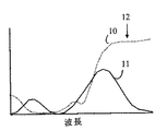
本発明はCIE1931標準に基づく表色系を参照することでより容易に理解することが出来る。しかしながら、以下の詳細説明からわかるように、本発明の原理は他の表色系にも適用することが可能である。ここで図1を参照するが、これは代表的な赤色素フィルタで得られる波長の関数としての色透過曲線が、CIE1931赤色プロファイルのカラープロファイルとどのように異なるかを示すものである。色素プロファイルは符号10に、CIE1931標準プロファイルは符号11に示した。図からわかるように、色素フィルタのカラープロファイルはCIE1931標準のものを著しく超える伸びを示している。同様に、青色及び緑色用に標準的に使用されている色素フィルタの色透過曲線も、図2及び図3に示したようにCIE1931標準の対応フィルタプロファイルよりも大幅に広い。図2は、代表的な緑色素フィルタで得られる波長の関数としての色透過曲線をCIE1931緑色プロファイルと比較したものである。色素プロファイルは符号20に示し、CIE1931標準プロファイルは符号21に示した。図3は青色素フィルタで得られる波長の関数としての色透過曲線をCIE1931青色プロファイルのカラープロファイルと比較したものである。色素プロファイルは符号30に示し、CIE1931標準プロファイルは符号31に示した。 The present invention can be more easily understood by referring to a color system based on the CIE 1931 standard. However, as will be appreciated from the detailed description below, the principles of the present invention can be applied to other color systems. Reference is now made to FIG. 1, which shows how the color transmission curve as a function of wavelength obtained with a typical red dye filter differs from the color profile of the CIE 1931 red profile. The dye profile is shown at 10 and the CIE 1931 standard profile is shown at 11. As can be seen, the color profile of the dye filter shows an elongation that is significantly greater than that of the CIE 1931 standard. Similarly, the color transmission curves of dye filters typically used for blue and green are also significantly wider than the corresponding filter profiles of the CIE 1931 standard, as shown in FIGS. FIG. 2 compares the color transmission curve as a function of wavelength obtained with a typical green dye filter with the CIE 1931 green profile. The dye profile is shown at 20 and the CIE 1931 standard profile is shown at 21. FIG. 3 compares the color transmission curve as a function of wavelength obtained with a blue dye filter with the color profile of the CIE 1931 blue profile. The dye profile is shown at 30 and the CIE 1931 standard profile is shown at 31.
本発明は、上述した色素フィルタを、これらの色素フィルタが対応する標準プロファイルを透過するように設計されたフィルタよりも大量の光を透過するスペクトル領域において、光を選択的に遮断する第2のフィルタと組み合わせることにより改良されたカラーフィルタを得ることが出来るという考えに基づいたものである。色素フィルタはフィルタ上の位置によって変化するものであるが、第2のフィルタはフィルタ全体を通じて実質的に変化しない透過関数を持っている。ここで図1に戻るが、赤色素フィルタは符号11に示す標準プロファイルを提供するフィルタよりも、符号12に示すスペクトル領域における光を大量に透過している。本発明は、この過剰に透過された光を除去する為の帯域遮断フィルタを用いている。赤色素フィルタの透過は
The present invention provides a second filter that selectively blocks light in the spectral region that transmits a greater amount of light than the filters described above that are designed to transmit the standard profile to which they correspond. This is based on the idea that an improved color filter can be obtained by combining with a filter. While the dye filter varies with position on the filter, the second filter has a transmission function that does not vary substantially throughout the filter. Returning now to FIG. 1, the red dye filter transmits more light in the spectral region indicated by
![]()
![]()
として、そして標準フィルタプロファイルの透過を And transmission of standard filter profiles
![]()
![]()
として示す。この説明の目的上、これらのフィルタの最高透過率は同じものとする。この場合、理想的な帯域遮断フィルタは、以下に挙げる透過率を持っている。 As shown. For purposes of this description, the maximum transmittance of these filters is the same. In this case, an ideal band cut-off filter has the transmittance described below.

同様の帯域遮断フィルタを、最終的な複合フィルタが所望の標準フィルタに近いものに仕上がるように他の色素フィルタにも設けることが出来る。色素ベースのフィルタは、対応する色に対し、より理想的な標準透過曲線よりも大幅に広い透過曲線を持つ傾向がある。例えば、青色フィルタの透過曲線中で遮断すべき帯域位置を図3における符号32及び符号33で示した。一般に、色素フィルタ透過曲線を所望される透過曲線により近い透過曲線へと変換する為に希釈しなければならない色素フィルタ透過曲線帯域は、1帯域又は2帯域ある。
Similar band-stop filters can be provided for other dye filters so that the final composite filter is finished close to the desired standard filter. Dye-based filters tend to have a much broader transmission curve for the corresponding color than the more ideal standard transmission curve. For example, the band positions to be blocked in the transmission curve of the blue filter are indicated by
以下の説明を明確にする為に、上述した色素フィルタをプライマリ空間変化フィルタと呼び、帯域遮断フィルタを共通スペクトルトリムフィルタと呼ぶものとする。本発明は、これらの共通スペクトルトリムフィルタを遮断すべき帯域の各々において最低透過率を持つ単一の複合フィルタへと組み合わせることが出来るという考えを利用したものである。このようなフィルタを構築する方法を以下に詳細に説明する。この説明の便宜上、各共通スペクトルトリムフィルタは、これが遮断する帯域以外のスペクトル領域においては、基本的に理想的な100%の透過率を持つものとして説明する。よってこのようなフィルタが複数積層された場合にも、遮断帯域と遮断帯域の間にあるスペクトル領域における透過率には基本的に変化は無い。従ってこのようなトリムフィルタのスタックを持つ単一の複合フィルタは、赤、緑及び青色素フィルタの上又は下に配置することが出来る。この結果、単一の色素フィルタよりも大幅に大きい物理寸法を持つトリムフィルタを利用することが出来、従って上述した寸法限界問題はより小さなものとなる。実際、単一の複合トリムフィルタは、何らかの形状パターニングをする場合でもわずかしか必要としない単一層としてカラーセンサアレイ全体の上又は下に配置することが出来るのである。 In order to clarify the following description, the above-described dye filter is referred to as a primary spatial change filter, and the band cut filter is referred to as a common spectrum trim filter. The present invention takes advantage of the idea that these common spectral trim filters can be combined into a single composite filter with the lowest transmission in each of the bands to be blocked. A method for constructing such a filter will be described in detail below. For convenience of explanation, each common spectrum trim filter is basically assumed to have an ideal transmittance of 100% in a spectral region other than the band that is cut off. Therefore, even when a plurality of such filters are stacked, there is basically no change in the transmittance in the spectral region between the stop band and the stop band. Thus, a single composite filter with such a stack of trim filters can be placed above or below the red, green and blue dye filters. As a result, a trim filter having a physical dimension that is significantly larger than that of a single dye filter can be utilized, thus making the dimensional limit problem described above smaller. In fact, a single composite trim filter can be placed above or below the entire color sensor array as a single layer that requires little if any shape patterning.
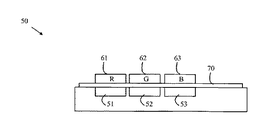
次に図4を参照するが、これは本発明の一実施例に基づくフィルタを用いたカラーセンサの断面を描いたものである。カラーセンサ50は3つのフォトディテクタ51〜53を含む。各フォトディテクタは、対応する色素フィルタにより覆われている。フォトディテクタ51〜53に対応するフィルタは、それぞれ符号61〜63で示した。複合トリムフィルタ70は、色素フィルタの透過曲線を上述した方式と同様の方式で「切り取る」為に用いられる。トリムフィルタ70は、フォトディテクタと色素フィルタとの間に配置されることが望ましいが、色素フィルタ上にトリムフィルタを配置した実施例とすることも可能である。
Reference is now made to FIG. 4, which depicts a cross-section of a color sensor using a filter according to one embodiment of the present invention. The
幾つかの代表的な色素フィルタとトリムフィルタの透過曲線を図5に示した。トリムフィルタの正規化された透過曲線は符号70に示し、赤、青、緑色素フィルタの正規化された透過曲線は、それぞれ符号71〜73に示した。フィルタの下にある赤色、青色及び緑色光を検出するフォトダイオードの応答曲線は、図6の符号81〜83にそれぞれ示した。この説明の便宜上、色素フィルタを、特定波長の光を選択的に吸収してそのフィルタ材料中の2つの原子又は分子エネルギー状態の間における遷移を誘発することにより、それを通過する光のカラースペクトルを変える何らかのフィルタと定義するものとする。従来のフォトリソグラフィー技術によりパターニングすることが出来る色素フィルタとしては、富士フィルム社製のものがある。
The transmission curves of some typical dye filters and trim filters are shown in FIG. The normalized transmission curves for the trim filter are shown at 70, and the normalized transmission curves for the red, blue and green dye filters are shown at 71-73, respectively. The response curves of the photodiodes for detecting red, blue and green light under the filter are indicated by
次にトリムフィルタを構成する方法を以下に詳細に説明する。推奨される帯域遮断フィルタは、厚さが均一な複数の透明層から構成された干渉フィルタであり、これらの層の隣接するもの同士は異なる屈折率を持っている。この種のフィルタは当該分野においては周知であり、本願においては、これらの詳細については説明しないものとする。説明の便宜上、このような層のスタックが、これらの層の厚さ及び屈折率により決まる波長の光を遮断するものであると述べるに留める。他の波長の光は遮断されない為、わずかに希釈されながらも層スタックを通過する。従ってこのような複数のフィルタを積層することにより、所定の波長群における各波長の光を遮断しつつも、所定波長群以外の波長の光は透過させる複合フィルタが提供されるのである。 Next, a method for configuring the trim filter will be described in detail below. The recommended band-cut filter is an interference filter composed of a plurality of transparent layers having a uniform thickness, and adjacent ones of these layers have different refractive indexes. This type of filter is well known in the art and will not be described in detail in this application. For convenience of explanation, it will be noted that such a stack of layers is intended to block light of a wavelength determined by the thickness and refractive index of these layers. Since other wavelengths of light are not blocked, they pass through the layer stack with slight dilution. Therefore, by laminating a plurality of such filters, a composite filter that transmits light of wavelengths other than the predetermined wavelength group while blocking light of each wavelength in the predetermined wavelength group is provided.
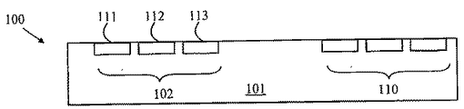
ここで図7〜図9を参照するが、これらは本発明の他の実施例に基づくフィルタを用いたカラーセンサアレイ100の様々な製造プロセス段階における断面図である。図7において、プロセスは複数のフォトダイオードをその中に設けた基板101から始まる。フォトダイオードセット例を符号102及び符号110に示した。フォトダイオードセットの各々は、符号111〜符号113に示した3つの別個のフォトダイオードを含んでいる。
Reference is now made to FIGS. 7-9, which are cross-sectional views at various stages of the manufacturing process of a
図8を見ると、基板101は堆積チャンバ中に入れられており、複合干渉フィルタの各層が基板表面に形成されている。干渉フィルタは当該分野においては周知である為、フィルタ構成の詳細についてはここでは説明しないものとする。遮断すべき2つの帯域に対応する層は符号121及び123に示した。層の様々な組成及び厚さは、各層に用いられる先駆物質組成及び堆積時間を調節することにより制御することが出来る為、基板を堆積処理中にチャンバから取り出す必要はない。従ってこの処理は経済的でもあり、歩留まりも高い。
Referring to FIG. 8, the
次に図9を参照するが、従来のフォトリソグラフィー技術により色素フィルタが帯域遮断フィルタ層の上に形成される。この実施例においては、赤色、青色及び緑色のスペクトル領域で透過性を持つ色素フィルタが使用されている。色素フィルタ例は符号131〜133に示した。
Referring now to FIG. 9, a dye filter is formed on the band-stop filter layer by conventional photolithography techniques. In this embodiment, dye filters that are transparent in the red, blue and green spectral regions are used. Examples of the dye filter are denoted by
上述した本発明の実施例は原色ろ波機能を得る為の色素フィルタと、色素フィルタの透過曲線端部を調節して目的とする透過関数に近いものを得る為の干渉フィルタを用いている。しかしながら、本発明はこれらのフィルタタイプの特定の組み合わせに限られたものではない。より広義に言えば、充分にパターニングし得るものであれば、これらの色素フィルタの代わりにどのようなフィルタ材料を使用しても良い。例えば、着色したフォトレジストを用いた色素フィルタを利用することも出来る。同様に、色素フィルタの透過曲線を変えて目的とするフィルタ機能に近づける為に1つ以上の色素フィルタ上に使用する帯域遮断フィルタも、どのような形式のものであっても良い。例えば、他の色素に基づく帯域通過フィルタを、それらの色素が異なる色素を利用する領域の作用に干渉する吸収帯を持たないものであれば利用することが出来る。 The above-described embodiments of the present invention use a dye filter for obtaining a primary color filtering function and an interference filter for obtaining an object close to the intended transmission function by adjusting the transmission curve end of the dye filter. However, the present invention is not limited to a specific combination of these filter types. In broader terms, any filter material may be used instead of these dye filters as long as they can be sufficiently patterned. For example, a dye filter using a colored photoresist can be used. Similarly, any type of band-cut filter used on one or more dye filters to change the transmission curve of the dye filter to approximate the desired filter function. For example, bandpass filters based on other dyes can be used as long as they do not have an absorption band that interferes with the action of regions that use different dyes.
次に図10を参照するが、これは本発明に基づくフィルタを用いた他のカラーセンサの実施例を描いた断面図である。上述した実施例では色素フィルタが形成される前にトリムフィルタを設けるものであったが、色素フィルタ上にトリムフィルタを配置した構成の実施例も可能である。その形成に色素フィルタを損傷する恐れのある環境を要する材料からトリムフィルタが作られる場合、そしてトリムフィルタがフォトディテクタ上に形成すべきものである場合、トリムフィルタは先に設けられなければならない。しかしながら、トリムフィルタを別途形成し、色素フィルタ上にボンディングした、或いは取り付けた実施例も可能である。カラーセンサアレイ200は、緩衝層204を色素フィルタ201〜203上に設け、この緩衝層へとトリムフィルタ層210を被着することにより、色素フィルタ上に配置されたトリムフィルタ層210を採用したものである。
Reference is now made to FIG. 10, which is a cross-sectional view depicting another color sensor embodiment using a filter according to the present invention. In the above-described embodiment, the trim filter is provided before the dye filter is formed. However, an embodiment in which the trim filter is arranged on the dye filter is also possible. If the trim filter is made from an environmentally demanding material whose formation can damage the dye filter, and if the trim filter is to be formed on a photodetector, the trim filter must be provided first. However, an embodiment in which a trim filter is separately formed and bonded or mounted on a dye filter is also possible. The
加えて、トリムフィルタの一部分を色素フィルタの下に設け、第2の部分を色素フィルタの上に設けたトリムフィルタ構成も、特定の状況下にあっては有利に用いることが出来る。例えば、赤外線を除去するトリムフィルタは、様々な色素フィルタ構成において有用である。従って、このフィルタをフォトダイオード上に設けることにより、複数の異なるカラーセンサアレイを異なる色素フィルタ及び/又はトリムフィルタに基づいて構築する為の新たな出発基板とすることが出来る。このような下地フィルタは図10の符号212に示した。
In addition, a trim filter configuration in which a portion of the trim filter is provided below the dye filter and a second portion is provided above the dye filter can also be used advantageously under certain circumstances. For example, a trim filter that removes infrared light is useful in various dye filter configurations. Therefore, providing this filter on a photodiode can be a new starting substrate for building a plurality of different color sensor arrays based on different dye filters and / or trim filters. Such a base filter is denoted by
先に式1に示した理想的なトリムフィルタは推奨されるものではあるが、より理想から離れた他のトリムフィルタを利用しても相当な利益を得ることが出来る。概して本発明は、トリムフィルタと色素フィルタの組み合わせが、色素フィルタのみとした場合の透過曲線よりも目的とするフィルタ機能に近い透過曲線を提供するものであった場合に利点を提供するものであると言える。 Although the ideal trim filter previously shown in Equation 1 is recommended, significant benefits can be obtained using other trim filters that are more distant from the ideal. In general, the present invention provides an advantage when the combination of a trim filter and a dye filter provides a transmission curve that is closer to the desired filter function than the transmission curve of the dye filter alone. It can be said.
上述した本発明の実施例は、CIE1931標準のフィルタを使って説明したものである。しかしながら、本発明の原理は、他のフィルタ標準を利用したカラーセンサアレイの製作にも適用することが出来る。更に、カラーセンサ中の色素フィルタの数は3つとは限らない。 The above-described embodiment of the present invention has been described using a CIE 1931 standard filter. However, the principles of the present invention can also be applied to the fabrication of color sensor arrays using other filter standards. Furthermore, the number of dye filters in the color sensor is not limited to three.
上述したように、理想的なトリムフィルタは、遮断帯域と遮断帯域の間にある波長を持つ光を吸収しない帯域遮断フィルタを利用したものである。しかしながら、これらの領域における若干の吸収は許容範囲に入るものであることに留意が必要である。トリムフィルタの遮断帯域間の透過曲線が実質的に一定である場合、吸収があったとしても対象となるカラーセンサのフォトディテクタの利得を調節することにより修正することが出来る。 As described above, an ideal trim filter uses a band cutoff filter that does not absorb light having a wavelength between the cutoff band and the cutoff band. However, it should be noted that some absorption in these areas is acceptable. If the transmission curve between the cutoff bands of the trim filter is substantially constant, even if there is absorption, it can be corrected by adjusting the gain of the photodetector of the target color sensor.
上述した本発明の実施例は、カラーセンサアレイを使って説明した。しかしながら、本発明に基づくフィルタは、透過曲線が空間的に変化する透過フィルタを要するいずれのアプリケーションにも適用可能である。 The embodiment of the present invention described above has been described using a color sensor array. However, the filter according to the present invention is applicable to any application that requires a transmission filter whose transmission curve varies spatially.
上述した説明及び添付図から、本発明に様々な変更が可能であることは当業者であれば明らかである。よって本発明は、本願請求項の範囲によってのみ限定されるものである。 It will be apparent to those skilled in the art from the foregoing description and accompanying drawings that various modifications can be made to the present invention. Therefore, the present invention is limited only by the scope of the claims.
上述した実施形態に即して本発明を説明すると、本発明は、部分的に透光性で、波長の関数としての透過関数を持つプライマリフィルタ層(61〜63)であって、前記透過関数が前記プライマリフィルタ層(61〜63)の空間的位置の関数として変化するものであり、前記プライマリフィルタ層(61〜63)の第1の位置においては第1の特性波長付近にある第1の波長帯域における光を透過し、前記プライマリフィルタが前記プライマリフィルタ層(61〜63)の第2の位置においては第2の特性波長付近にある第2の波長帯域における光を透過することを特徴とする前記プライマリフィルタ層(61〜63)と、そして前記第1及び第2の位置の上に設けられた材料層を有し、前記第1及び第2の特性波長の間にある第1のトリム波長の光を選択的に減衰させる第1のトリムフィルタ(70)であって、前記第1及び第2の位置におけるものと実質的に同じ波長の関数としての透過関数を持つことを特徴とする前記第1のトリムフィルタ(70)とを具備したことを特徴とするカラーフィルタを提供する。 The present invention will be described in the context of the above-described embodiment. The present invention is a primary filter layer (61-63) that is partially translucent and has a transmission function as a function of wavelength, the transmission function. Changes as a function of the spatial position of the primary filter layer (61-63), and the first position of the primary filter layer (61-63) is in the vicinity of the first characteristic wavelength. Transmitting light in a wavelength band, wherein the primary filter transmits light in a second wavelength band near the second characteristic wavelength at the second position of the primary filter layer (61-63). A first filter layer (61-63), and a material layer provided on the first and second positions, the first filter layer being between the first and second characteristic wavelengths. A first trim filter (70) for selectively attenuating light of a wavelength, characterized in that it has a transmission function as a function of substantially the same wavelength as in the first and second positions. A color filter comprising the first trim filter (70) is provided.
好ましくは、前記第1のトリムフィルタ(70)は、更に第2のトリム波長の光を選択的に減衰させるものであり、前記第1のトリム波長が前記第1及び第2の特性波長の一方よりも低く、前記第2のトリム波長がその特性波長よりも大きいものとされる。 Preferably, the first trim filter (70) further selectively attenuates light having a second trim wavelength, and the first trim wavelength is one of the first and second characteristic wavelengths. And the second trim wavelength is greater than its characteristic wavelength.
好ましくは、前記第1のトリムフィルタ(70)は、干渉フィルタを含むものとされる。 Preferably, the first trim filter (70) includes an interference filter.
好ましくは、前記プライマリフィルタ層(61〜63)は、前記第1の位置に配置された第1の着色フィルタ(61)と前記第2の位置に配置された第2の着色フィルタ(62)を含む。 Preferably, the primary filter layer (61-63) includes a first colored filter (61) disposed at the first position and a second colored filter (62) disposed at the second position. Including.
好ましくは、前記第1及び第2の着色フィルタ(61、62)は、前記第1のトリムフィルタ層(121)の上に配置されたものとされる。 Preferably, the first and second coloring filters (61, 62) are disposed on the first trim filter layer (121).
好ましくは、第2のトリムフィルタ(212)を更に具備し、前記第2のトリムフィルタ(212)が前記特性波長及び前記第1のトリム波長とは異なる第2の波長の光を選択的に減衰させる材料層を含む。 Preferably, the apparatus further includes a second trim filter (212), and the second trim filter (212) selectively attenuates light having a second wavelength different from the characteristic wavelength and the first trim wavelength. A material layer to be included.
好ましくは、前記着色フィルタ(61、62、63)は、前記第1及び第2のトリムフィルタ(210、212)の間に配置される。 Preferably, the coloring filter (61, 62, 63) is disposed between the first and second trim filters (210, 212).
さらに本発明は、カラーフィルタを製作する為の方法であって、第1のトリムフィルタ層(121)を基板(101)へと被着するステップと、そして部分的に透光性のプライマリフィルタ層(131〜133)を前記第1のトリムフィルタ層(121)へと被着するステップであって、前記プライマリフィルタ層(131〜133)が波長の関数としての透過関数を持ち、前記透過関数が前記プライマリフィルタ層(131〜133)上の空間的位置の関数として変化するものであり、前記プライマリフィルタが、前記プライマリフィルタ層(131〜133)の第1の位置においては第1の特性波長付近の第1の波長帯域にある光を透過し、前記プライマリフィルタ層(131〜133)の第2の位置においては第2の特性波長付近の第2の波長帯域にある光を透過するステップとを有し、前記第1のトリムフィルタ層(121)が、前記第1及び第2の位置に重なり、前記第1及び第2の特性波長間にある第1のトリム波長の光を選択的に減衰させる材料層を含み、前記第1のトリムフィルタ(70)が前記第1及び第2の位置におけるものと実質的に同じ波長の関数としての透過関数を持っていることを特徴とする方法を提供する。 Furthermore, the present invention is a method for producing a color filter comprising the steps of depositing a first trim filter layer (121) on a substrate (101), and a partially transparent primary filter layer. (131-133) to the first trim filter layer (121), wherein the primary filter layer (131-133) has a transmission function as a function of wavelength, and the transmission function is Varies as a function of the spatial position on the primary filter layer (131-133), the primary filter being near a first characteristic wavelength at a first position of the primary filter layer (131-133) And transmits light in the first wavelength band of the first filter layer (131 to 133) at the second position near the second characteristic wavelength. The first trim filter layer (121) overlaps the first and second positions and is between the first and second characteristic wavelengths. A layer of material that selectively attenuates light of a first trim wavelength, wherein the first trim filter (70) is a transmission function as a function of substantially the same wavelength as in the first and second positions. To provide a method characterized by having
好ましくは、前記第1のトリムフィルタ層(121)が更に第2のトリム波長の光も選択的に減衰させるものであり、前記第1の波長が前記特性波長の1つよりも小さく、前記第2の波長がその特性波長よりも大きいものとされる。 Preferably, the first trim filter layer (121) further selectively attenuates the light of the second trim wavelength, the first wavelength being smaller than one of the characteristic wavelengths, The second wavelength is larger than the characteristic wavelength.
好ましくは、前記第1のトリムフィルタ層(121)が複数の透明層を含み、その中の隣接する層同士が異なる屈折率を持つものとされる。 Preferably, the first trim filter layer (121) includes a plurality of transparent layers, and adjacent layers among them have different refractive indexes.
好ましくは、第2のトリムフィルタ層(212)を前記カラーフィルタ層(201〜203)へと被着することにより前記カラーフィルタ層を前記第1及び第2のトリムフィルタ層(210、212)で挟みこむステップを更に有し、前記第2のトリムフィルタ層(212)が前記第1及び第2の位置へと重なり、前記第1のトリム波長、前記第1の特性波長及び前記第2の特性波長とは異なる第2のトリム波長の光を選択的に減衰させる材料層を含み、前記第2のトリムフィルタが前記第1及び第2の位置におけるものと実質的に同じ波長の関数としての透過関数を持つものとされる。 Preferably, the color filter layer is applied to the first and second trim filter layers (210, 212) by depositing a second trim filter layer (212) onto the color filter layers (201 to 203). And sandwiching the second trim filter layer (212) to the first and second positions so that the first trim wavelength, the first characteristic wavelength, and the second characteristic are included. A layer of material that selectively attenuates light of a second trim wavelength different from the wavelength, wherein the second trim filter transmits as a function of substantially the same wavelength as in the first and second positions. It is assumed to have a function.
61〜63、131〜133 プライマリフィルタ層
70、210 第1のトリムフィルタ
121 第1のトリムフィルタ層
201〜203 カラーフィルタ層
212 第2のトリムフィルタ
61-63, 131-133
Claims (11)
前記第1及び第2の位置の上に設けられた材料層を有し、前記第1及び第2の特性波長の間にある第1のトリム波長の光を選択的に減衰させる第1のトリムフィルタであって、前記第1及び第2の位置におけるものと実質的に同じ波長の関数としての透過関数を持つ第1のトリムフィルタとを具備したことを特徴とするカラーフィルタ。 A primary filter layer that is partially translucent and has a transmission function as a function of wavelength, wherein the transmission function varies as a function of spatial position, and has a first characteristic at the first position. The primary filter layer that transmits light in a first wavelength band near a wavelength and transmits light in a second wavelength band near a second characteristic wavelength at a second position;
A first trim having a material layer provided on the first and second positions and selectively attenuating light having a first trim wavelength between the first and second characteristic wavelengths A color filter comprising: a first trim filter having a transmission function as a function of substantially the same wavelength as in the first and second positions.
部分的に透光性のプライマリフィルタ層を前記第1のトリムフィルタ層へと被着するステップであって、前記プライマリフィルタ層が波長の関数としての透過関数を持ち、前記透過関数が前記プライマリフィルタ層上の空間的位置の関数として変化するものであり、前記プライマリフィルタが、第1の位置で第1の特性波長付近の第1の波長帯域にある光を透過し、第2の位置で第2の特性波長付近の第2の波長帯域にある光を透過するステップとを有し、
前記第1のトリムフィルタ層は、前記第1及び第2の位置に重なり、前記第1及び第2の特性波長間にある第1のトリム波長の光を選択的に減衰させる材料層を含み、前記第1及び第2の位置におけるものと実質的に同じ波長の関数としての透過関数を持つようにすることを特徴とする方法。 A method for making a color filter, comprising depositing a first trim filter layer on a substrate;
Depositing a partially transmissive primary filter layer onto the first trim filter layer, the primary filter layer having a transmission function as a function of wavelength, wherein the transmission function is the primary filter layer; The primary filter transmits light in the first wavelength band near the first characteristic wavelength at the first position and the first filter at the second position. Transmitting light in a second wavelength band near the characteristic wavelength of 2,
The first trim filter layer includes a material layer that overlaps the first and second positions and selectively attenuates light of a first trim wavelength that is between the first and second characteristic wavelengths; Having a transmission function as a function of substantially the same wavelength as in the first and second positions.
The method further comprises the step of sandwiching the color filter layer between the first and second trim filter layers by depositing a second trim filter layer on the color filter layer, wherein the second trim filter layer comprises: A material layer that overlaps the first and second positions and selectively attenuates light having a second trim wavelength different from the first trim wavelength, the first characteristic wavelength, and the second characteristic wavelength. 9. The method of claim 8, wherein the second trim filter has a transmission function as a function of substantially the same wavelength as in the first and second positions. .
Applications Claiming Priority (1)
| Application Number | Priority Date | Filing Date | Title |
|---|---|---|---|
| US10/804,286 US20050207044A1 (en) | 2004-03-18 | 2004-03-18 | Color filter and method for fabricating the same |
Publications (2)
| Publication Number | Publication Date |
|---|---|
| JP2005266811A true JP2005266811A (en) | 2005-09-29 |
| JP2005266811A5 JP2005266811A5 (en) | 2008-04-24 |
Family
ID=34985983
Family Applications (1)
| Application Number | Title | Priority Date | Filing Date |
|---|---|---|---|
| JP2005076882A Withdrawn JP2005266811A (en) | 2004-03-18 | 2005-03-17 | Color filter and its manufacturing method |
Country Status (3)
| Country | Link |
|---|---|
| US (1) | US20050207044A1 (en) |
| JP (1) | JP2005266811A (en) |
| CN (1) | CN1670607A (en) |
Families Citing this family (7)
| Publication number | Priority date | Publication date | Assignee | Title |
|---|---|---|---|---|
| WO2006055684A2 (en) * | 2004-11-16 | 2006-05-26 | Datacolor Holding Ag | Method for designing a colorimeter having integral cie color-matching filters |
| US7593105B2 (en) * | 2004-11-17 | 2009-09-22 | Datacolor Holding Ag | Tristimulus colorimeter having integral dye filters |
| US7580130B2 (en) * | 2005-03-23 | 2009-08-25 | Datacolor Holding Ag | Method for designing a colorimeter having integral illuminant-weighted CIE color-matching filters |
| US7474402B2 (en) * | 2005-03-23 | 2009-01-06 | Datacolor Holding Ag | Reflectance sensor for integral illuminant-weighted CIE color matching filters |
| US7375803B1 (en) * | 2006-05-18 | 2008-05-20 | Canesta, Inc. | RGBZ (red, green, blue, z-depth) filter system usable with sensor systems, including sensor systems with synthetic mirror enhanced three-dimensional imaging |
| US20100208266A1 (en) * | 2009-02-17 | 2010-08-19 | Colman Shannon | Tristimulus colorimeter having integral dye filters |
| KR102369633B1 (en) * | 2015-08-31 | 2022-03-03 | 엘지디스플레이 주식회사 | Organic light emitting diode display device and manufacturing method for the same |
Family Cites Families (5)
| Publication number | Priority date | Publication date | Assignee | Title |
|---|---|---|---|---|
| US3996461A (en) * | 1975-03-31 | 1976-12-07 | Texas Instruments Incorporated | Silicon photosensor with optical thin film filter |
| JPS57184937A (en) * | 1981-05-08 | 1982-11-13 | Omron Tateisi Electronics Co | Color discriminating element |
| US5166784A (en) * | 1985-10-25 | 1992-11-24 | Canon Kabushiki Kaisha | Original reading apparatus, having a filter, for reading a color original |
| US5073008A (en) * | 1987-12-11 | 1991-12-17 | Fuji Photo Film Co., Ltd. | Multicolor interference filters with side surfaces to prevent entry of undesirable light |
| US5648653A (en) * | 1993-10-22 | 1997-07-15 | Canon Kabushiki Kaisha | Optical filter having alternately laminated thin layers provided on a light receiving surface of an image sensor |
-
2004
- 2004-03-18 US US10/804,286 patent/US20050207044A1/en not_active Abandoned
-
2005
- 2005-03-17 JP JP2005076882A patent/JP2005266811A/en not_active Withdrawn
- 2005-03-18 CN CN200510055468.1A patent/CN1670607A/en active Pending
Also Published As
| Publication number | Publication date |
|---|---|
| US20050207044A1 (en) | 2005-09-22 |
| CN1670607A (en) | 2005-09-21 |
Similar Documents
| Publication | Publication Date | Title |
|---|---|---|
| JP4899008B2 (en) | Improved color photodetector array and method of manufacturing the same | |
| US11031423B2 (en) | Imaging element and camera system | |
| US8227883B2 (en) | Solid-state imaging device and camera | |
| US10819922B2 (en) | Solid-state imaging element and imaging device | |
| CN106612420B (en) | Color filter array and imaging sensor | |
| US9666620B2 (en) | Stacked filter and image sensor containing the same | |
| US20210033466A1 (en) | Optical filter and spectrometer including the same | |
| TWI469634B (en) | Visible and infrared dual mode imaging system | |
| US7858921B2 (en) | Guided-mode-resonance transmission color filters for color generation in CMOS image sensors | |
| US9658372B2 (en) | Optical filtering structure in the visible and/or infrared domain | |
| CN105514132B (en) | The bimodulus imaging sensor and its method of color filter array with Signal separator | |
| US20080315339A1 (en) | Solid-state imaging device | |
| US20080251873A1 (en) | Solid-state imaging device, manufactoring method thereof and camera | |
| US20160099280A1 (en) | Image sensors and methods of forming the same | |
| JP2005266811A (en) | Color filter and its manufacturing method | |
| US8748213B2 (en) | Light transmission member, image pickup device, and method of manufacturing same | |
| KR20110003696A (en) | Optical filter array for the single chip three-dimension color image sensor and method for manufacturing same | |
| KR20140068042A (en) | Image pickup apparatus and filter | |
| JP2007013188A (en) | Color image sensor | |
| JP2010212306A (en) | Solid-state image device | |
| CN101371360A (en) | Solid state imaging device and camera | |
| EP3450938B1 (en) | An image sensor and an imaging apparatus | |
| JPH02166767A (en) | Color solid state image sensor and manufacture thereof | |
| KR100700264B1 (en) | Method for fabricating color filter of image sensor | |
| JP2008153308A (en) | Solid-state image sensing device and camera |
Legal Events
| Date | Code | Title | Description |
|---|---|---|---|
| RD03 | Notification of appointment of power of attorney |
Free format text: JAPANESE INTERMEDIATE CODE: A7423 Effective date: 20060412 |
|
| A711 | Notification of change in applicant |
Free format text: JAPANESE INTERMEDIATE CODE: A711 Effective date: 20070326 |
|
| A521 | Request for written amendment filed |
Free format text: JAPANESE INTERMEDIATE CODE: A523 Effective date: 20080311 |
|
| A621 | Written request for application examination |
Free format text: JAPANESE INTERMEDIATE CODE: A621 Effective date: 20080311 |
|
| A761 | Written withdrawal of application |
Free format text: JAPANESE INTERMEDIATE CODE: A761 Effective date: 20090818 |