JP2005294786A - High-brightness chip-type light emitting diode - Google Patents
High-brightness chip-type light emitting diode Download PDFInfo
- Publication number
- JP2005294786A JP2005294786A JP2004134892A JP2004134892A JP2005294786A JP 2005294786 A JP2005294786 A JP 2005294786A JP 2004134892 A JP2004134892 A JP 2004134892A JP 2004134892 A JP2004134892 A JP 2004134892A JP 2005294786 A JP2005294786 A JP 2005294786A
- Authority
- JP
- Japan
- Prior art keywords
- light emitting
- emitting diode
- chip
- type light
- convex lens
- Prior art date
- Legal status (The legal status is an assumption and is not a legal conclusion. Google has not performed a legal analysis and makes no representation as to the accuracy of the status listed.)
- Pending
Links
- 229920005989 resin Polymers 0.000 claims abstract description 12
- 239000011347 resin Substances 0.000 claims abstract description 12
- 230000003287 optical effect Effects 0.000 claims abstract description 8
- 239000000758 substrate Substances 0.000 abstract 1
- 238000001721 transfer moulding Methods 0.000 abstract 1
- 238000007789 sealing Methods 0.000 description 8
- 239000000853 adhesive Substances 0.000 description 2
- 230000001070 adhesive effect Effects 0.000 description 2
- 239000000463 material Substances 0.000 description 2
- OAICVXFJPJFONN-UHFFFAOYSA-N Phosphorus Chemical group [P] OAICVXFJPJFONN-UHFFFAOYSA-N 0.000 description 1
- BQCADISMDOOEFD-UHFFFAOYSA-N Silver Chemical compound [Ag] BQCADISMDOOEFD-UHFFFAOYSA-N 0.000 description 1
- 239000011248 coating agent Substances 0.000 description 1
- 238000000576 coating method Methods 0.000 description 1
- 239000003086 colorant Substances 0.000 description 1
- 239000002131 composite material Substances 0.000 description 1
- 238000010586 diagram Methods 0.000 description 1
- 230000000694 effects Effects 0.000 description 1
- 239000003822 epoxy resin Substances 0.000 description 1
- 229910052751 metal Inorganic materials 0.000 description 1
- 239000002184 metal Substances 0.000 description 1
- 238000000034 method Methods 0.000 description 1
- 238000007747 plating Methods 0.000 description 1
- 229920000647 polyepoxide Polymers 0.000 description 1
- 229910052709 silver Inorganic materials 0.000 description 1
- 239000004332 silver Substances 0.000 description 1
Images
Landscapes
- Led Device Packages (AREA)
Abstract
Description
この発明は、チップ型発光ダイオードに関するものである。 The present invention relates to a chip type light emitting diode.
従来、この種のチップ型発光ダイオードとしては、例えば図10に示したものが知られている。このチップ型発光ダイオード1は、プリント基板7に面に内部接続電極8,9が左右形成され、外部接続電極10,11とそれぞれと接続されている。内部接続電極8の上に導電性接着剤(図示せず)によって発光ダイオード素子5を固着すると共に、発光ダイオード素子5の上面電極と内部接続電極9とをボンディングワイヤー6で接続し、この周りを取り囲むように、外方に向かって傾斜する反射面3を設け、発光ダイオード素子5及びボンディングワイヤー6を樹脂封止体2によって保護した構造のものである。 Conventionally, as this type of chip type light emitting diode, for example, the one shown in FIG. 10 is known. The chip type
上述のチップ型発光ダイオード1は、発光ダイオード素子5から発光される光を反射面3で上方に向けて反射させることで光の集光性を高めることができる。 The above-described chip-type
しかしながら、以上の技術によれば、図10に示したように、発光ダイオード素子5から天面へ放出される光線12は屈折により光の発散と全反射という光の損失が生じてしまうといった問題があった。
そこで、本発明は、発光ダイオード素子5から天面へ放出される光線12の発散と全反射を防ぎ、更に光線12の指向特性の調整が可能であり、光の利用効率高い発光ダイオードを提供することにある。However, according to the above technique, as shown in FIG. 10, the light beam 12 emitted from the light-emitting
Therefore, the present invention provides a light emitting diode that can prevent the divergence and total reflection of the light beam 12 emitted from the light
以上の課題を解決するために、本発明の請求項1に係るチップ型発光ダイオードは、発光ダイオード素子が発する光の光軸に対して同心円的に凸レンズ部を構成し、更にその周囲に反射面を配置したことを特徴とする。 In order to solve the above problems, a chip-type light emitting diode according to
請求項2の発明は、請求項1に記載のチップ型発光ダイオードにおいて、前記凸レンズは上面部分と側面部分から構成し、その断面が凸字状をなすことを特徴とする。 According to a second aspect of the present invention, in the chip type light emitting diode according to the first aspect, the convex lens is composed of an upper surface portion and a side surface portion, and a cross section thereof has a convex shape.
請求項3の発明は、請求項1に記載のチップ型発光ダイオードにおいて、前記反射面が曲面或は傾斜面を有していることを特徴とする。 According to a third aspect of the present invention, in the chip type light emitting diode according to the first aspect, the reflecting surface has a curved surface or an inclined surface.
請求項4の発明は、請求項1に記載の発光ダイオードにおいて、前記発光素子が2個以上の多数個を直線に搭載され、発光素子と同数の前記凸レンズ部と、同数の前記反射面を配置したことを特徴とする。 According to a fourth aspect of the present invention, in the light emitting diode according to the first aspect, a plurality of the light emitting elements are mounted in a straight line, and the same number of convex lens portions as the light emitting elements and the same number of the reflecting surfaces are arranged. It is characterized by that.
請求項5の発明は、請求項1に記載の発光ダイオードにおいて、前記発光素子が3個を正三角形に搭載され、発光素子と同数の前記凸レンズ部と、同数の前記反射面を配置したことを特徴とする。 According to a fifth aspect of the present invention, in the light emitting diode according to the first aspect, three of the light emitting elements are mounted in an equilateral triangle, and the same number of convex lens portions as the light emitting elements and the same number of the reflecting surfaces are arranged. Features.
請求項6の発明は、請求項1乃至請求項5に記載の発光ダイオードにおいて、発光素子を搭載するプリント基板がパラボラ構造を有していることを特徴とする。 According to a sixth aspect of the present invention, in the light emitting diode according to the first to fifth aspects, the printed circuit board on which the light emitting element is mounted has a parabolic structure.
以上説明したように、本発明に係るチップ型発光ダイオードによれば、透明樹脂により発光ダイオード素子が発する光の光軸に対して同心円的に凸レンズ部を構成し、更にその周囲に反射面を配置したことで、凸字状レンズにより、発光ダイオード素子から天面へ放出される光線の発散と全反射を防ぎ、曲面或は傾斜面の反射面により、光線の指向特性の調整が可能であり、光の集光性を高め、利用効率高い発光ダイオードができる。 As described above, according to the chip-type light emitting diode according to the present invention, the convex lens portion is formed concentrically with respect to the optical axis of the light emitted from the light emitting diode element by the transparent resin, and the reflection surface is arranged around the convex lens portion. Therefore, the convex lens prevents divergence and total reflection of light emitted from the light emitting diode element to the top surface, and the directivity of the light can be adjusted by the curved or inclined reflecting surface. A light-emitting diode with high light utilization and high utilization efficiency can be obtained.
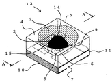
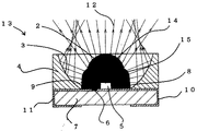
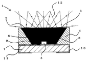
以下、添付図面に基づいて本発明に係るチップ型発光ダイオードの実施形態を詳細に説明する。図1、図2示した第1実施形態に係るチップ型発行ダイオードにおいて、図1はチップ型発行ダイオードの外観形状を示した斜視図、図2は図1におけるA−Aに沿った断面図又は光路図である。 Hereinafter, embodiments of a chip-type light emitting diode according to the present invention will be described in detail with reference to the accompanying drawings. 1 and FIG. 2, in the chip-type emitting diode according to the first embodiment, FIG. 1 is a perspective view showing an external shape of the chip-type emitting diode, and FIG. 2 is a cross-sectional view taken along line AA in FIG. It is an optical path diagram.
図1、図2を参照すると、本発明に係るチップ型発光ダイオードの一実施形態が符号13で示されており、このチップ型発光ダイオード13は、プリント基板7上面に内部接続電極8,9が左右形成されている。その内部接続電極8,9はプリント基板7の左右側面と裏面左右側に外部接続電極10,11それぞれと接続されている。 1 and 2, an embodiment of a chip type light emitting diode according to the present invention is indicated by
前記内部接続電極8の上面には発光部としての発光ダイオード素子5が載置され、その下面電極が導電性接着剤(図示せず)を介して固着されている。また、発光ダイオード素子5の上面電極は内部接続電極9にボンディングワイヤー6によって接続されている。そのため、外部接続電極10,11から内部接続電極8,9を介して発光ダイオード素子5に電流が供給され、発光ダイオード素子5が発光する。上記発光ダイオード素子5の種類や発光色は何ら限定されるものではない。 A light
前記発光ダイオード素子5及びボンディングワイヤー6は、プリント基板7上面に設けられた樹脂封止体2によって被覆されている。この樹脂封止体2は、発光ダイオード素子5の光軸に対して同心円的に凸字状レンズ(樹脂封止体2)に形成されたもので、前述の発光ダイオード素子5及びボンディングワイヤー6の他、内部接続電極8,9を被覆している。樹脂封止体2(凸字状レンズ)によって、発光ダイオード素子5から天面へ放出される光線12の発散と全反射を防ぎ、更に光線12の指向特性の調整が可能である。樹脂封止体2の材料には例えば透明のエポキシ系樹脂が用いられる。 The light
前記樹脂封止体2の周囲に反射面3を配置し、反射面3の曲面の曲率或は傾斜面の角度によって、反射光線12の指向性の調整ができる。反射板4の材料は伝熱性が良い、光反射率の高い金属Alが用いられ、或は、反射面3に反射率高い白塗装や銀メッキなどが施されている。 The
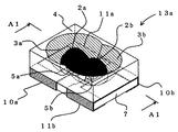
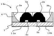
図3、図4は本発明に係るチップ型発光ダイオードの第2実施形態(2個発光素子搭載例)を示したものである。このチップ型発光ダイオード13aは、発光ダイオード素子5a,5bにはそれぞれのレンズ、反射面を有していることで、発光ダイオード素子5a,5bが発する光はそれぞれのレンズと反射面で制御し、チップ型発光ダイオード13aの薄型化ができる。2個発光素子で更に高輝度化ができる。 3 and 4 show a second embodiment of the chip-type light emitting diode according to the present invention (example of mounting two light emitting elements). In this chip type
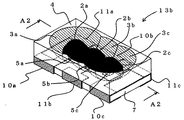
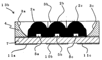
図5、図6は本発明に係るチップ型発光ダイオードの第2実施形態(3個発光素子搭載例)を示したものである。このチップ型発光ダイオード13bは、発光ダイオード素子5a,5b,5cは等距離直線に搭載され、それぞれのレンズ、反射面を有していることで、発光ダイオード素子5a,5b,5cが発する光はそれぞれのレンズと反射面で制御し、チップ型発光ダイオード13b薄型化ができる。2個発光素子より更に高輝度化ができる。(もっと輝度を求めたときは3個以上発光素子の搭載もできる)しかも、発光素子赤、グリーン、ブルーの3色搭載ができる。 5 and 6 show a second embodiment of the chip type light emitting diode according to the present invention (an example in which three light emitting elements are mounted). In the chip type light emitting diode 13b, the light
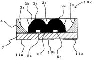
図7、図8は本発明に係るチップ型発光ダイオードの第3実施形態を示したものである。このチップ型発光ダイオード13cは、発光ダイオード素子5a,5b,5cは正三角形に搭載され、それぞれのレンズ、反射面を有していることで、発光ダイオード素子5a,5b,5cが発する光はそれぞれのレンズと反射面で制御し、チップ型発光ダイオード13c薄型化ができる。第2実施形態(3個発光素子搭載例)より発光ダイオード素子5a,5b,5c間の距離が一致であることで、発光素子赤、グリーン、ブルーの3色搭載するとき更に混色効果一層高めることができる。 7 and 8 show a third embodiment of the chip type light emitting diode according to the present invention. In this chip type light emitting diode 13c, the light
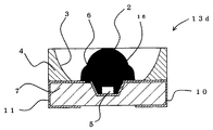
図9は本発明に係るチップ型発光ダイオードの第4実施形態(1個発光素子搭載例)を示したものである。 このチップ型発光ダイオード13dは、発光ダイオード素子5を搭載するプリント基板7にメッキされたパラボラ16を構成することにより、発光ダイオード素子5の横からの光モレ防止で更に高輝度化ができる。または、パラボラ16に蛍光体をボンディングし、複合素子にも適応することになれている。 FIG. 9 shows a fourth embodiment of the chip type light emitting diode according to the present invention (an example in which one light emitting element is mounted). This chip type light emitting diode 13d can be further enhanced in brightness by preventing light leakage from the side of the light
1 従来のチップ型発光ダイオード
2,2a,2b,2c 樹脂封止体(レンズ)
3,3a,3b,3c 反射面
4 反射板
5,5a,5b,5c 発光ダイオード素子(発光部)
6 ボンディングワイヤー
7 プリント基板
8,9 内部接続用電極
10,11 外部接続用電極
12 光線
13,13a,13b,13c,13d チップ型発光ダイオード
14 レンズ上面部曲面
15 レンズ側面部曲面
16 パラボラ1 Conventional chip type
3, 3a, 3b,
6
Claims (6)
Priority Applications (1)
| Application Number | Priority Date | Filing Date | Title |
|---|---|---|---|
| JP2004134892A JP2005294786A (en) | 2004-03-31 | 2004-03-31 | High-brightness chip-type light emitting diode |
Applications Claiming Priority (1)
| Application Number | Priority Date | Filing Date | Title |
|---|---|---|---|
| JP2004134892A JP2005294786A (en) | 2004-03-31 | 2004-03-31 | High-brightness chip-type light emitting diode |
Publications (1)
| Publication Number | Publication Date |
|---|---|
| JP2005294786A true JP2005294786A (en) | 2005-10-20 |
Family
ID=35327336
Family Applications (1)
| Application Number | Title | Priority Date | Filing Date |
|---|---|---|---|
| JP2004134892A Pending JP2005294786A (en) | 2004-03-31 | 2004-03-31 | High-brightness chip-type light emitting diode |
Country Status (1)
| Country | Link |
|---|---|
| JP (1) | JP2005294786A (en) |
Cited By (6)
| Publication number | Priority date | Publication date | Assignee | Title |
|---|---|---|---|---|
| KR100700201B1 (en) | 2005-09-01 | 2007-03-27 | 에스엘 주식회사 | Luminous lamp |
| JP2008004640A (en) * | 2006-06-20 | 2008-01-10 | Toyoda Gosei Co Ltd | Light emitting device |
| CN103574499A (en) * | 2012-07-18 | 2014-02-12 | 欧司朗股份有限公司 | Lens module and illuminating device provided with lens module |
| JP2014521227A (en) * | 2011-07-18 | 2014-08-25 | ヘレーウス ノーブルライト ゲゼルシャフト ミット ベシュレンクテル ハフツング | Optoelectronic module with improved optics |
| DE102009016683B4 (en) * | 2008-12-24 | 2015-06-25 | Industrial Technology Research Institute | Multichip LED |
| KR20200129973A (en) * | 2019-05-10 | 2020-11-18 | 주식회사 라이트전자 | Light emitting device package |
-
2004
- 2004-03-31 JP JP2004134892A patent/JP2005294786A/en active Pending
Cited By (8)
| Publication number | Priority date | Publication date | Assignee | Title |
|---|---|---|---|---|
| KR100700201B1 (en) | 2005-09-01 | 2007-03-27 | 에스엘 주식회사 | Luminous lamp |
| JP2008004640A (en) * | 2006-06-20 | 2008-01-10 | Toyoda Gosei Co Ltd | Light emitting device |
| DE102009016683B4 (en) * | 2008-12-24 | 2015-06-25 | Industrial Technology Research Institute | Multichip LED |
| JP2014521227A (en) * | 2011-07-18 | 2014-08-25 | ヘレーウス ノーブルライト ゲゼルシャフト ミット ベシュレンクテル ハフツング | Optoelectronic module with improved optics |
| US9593823B2 (en) | 2011-07-18 | 2017-03-14 | Heraeus Noblelight Gmbh | Optoelectronic module with improved optical system |
| CN103574499A (en) * | 2012-07-18 | 2014-02-12 | 欧司朗股份有限公司 | Lens module and illuminating device provided with lens module |
| KR20200129973A (en) * | 2019-05-10 | 2020-11-18 | 주식회사 라이트전자 | Light emitting device package |
| KR102244386B1 (en) * | 2019-05-10 | 2021-05-07 | 주식회사 라이트전자 | Light emitting device package |
Similar Documents
| Publication | Publication Date | Title |
|---|---|---|
| KR101081069B1 (en) | Light emitting device and light unit using the same | |
| JP4535928B2 (en) | Semiconductor light emitting device | |
| JP4744178B2 (en) | Light emitting diode | |
| JP4182783B2 (en) | LED package | |
| US8030762B2 (en) | Light emitting diode package having anodized insulation layer and fabrication method therefor | |
| JP3716252B2 (en) | Light emitting device and lighting device | |
| KR101039881B1 (en) | Light emitting element and light unit using same | |
| JP5509307B2 (en) | Light emitting diode package | |
| WO2001013437A1 (en) | Chip semiconductor light-emitting device | |
| JP7522529B2 (en) | Light-emitting device | |
| TW200425547A (en) | Led lamp | |
| JP2012234906A (en) | LIGHT EMITTING DEVICE AND LIGHTING DEVICE USING THE SAME | |
| TW201727945A (en) | Illuminating device | |
| JP2008244165A (en) | Lighting device | |
| US10804249B2 (en) | Light-emitting device with light-reflective and light-absorbing pieces layered on a surface | |
| JP2016122693A (en) | Light emission device | |
| JP2005109212A (en) | Semiconductor light emitting device | |
| JP2007096285A (en) | Light-emitting element mounting substrate, light-emitting element storage package, light-emitting device, and lighting device | |
| JP2008251664A (en) | Lighting device | |
| WO2024016697A1 (en) | Light source, light source module and display device | |
| JP2006261375A (en) | Led light source device | |
| JP5745784B2 (en) | Light emitting diode | |
| JP5350947B2 (en) | Light emitting diode | |
| JP2005294786A (en) | High-brightness chip-type light emitting diode | |
| JP2008243864A (en) | Light-emitting device and surface light-emitting device using the same |
