JP2005294741A - Electrical junction box - Google Patents
Electrical junction box Download PDFInfo
- Publication number
- JP2005294741A JP2005294741A JP2004111173A JP2004111173A JP2005294741A JP 2005294741 A JP2005294741 A JP 2005294741A JP 2004111173 A JP2004111173 A JP 2004111173A JP 2004111173 A JP2004111173 A JP 2004111173A JP 2005294741 A JP2005294741 A JP 2005294741A
- Authority
- JP
- Japan
- Prior art keywords
- hole
- case
- locking
- heat radiating
- radiating plate
- Prior art date
- Legal status (The legal status is an assumption and is not a legal conclusion. Google has not performed a legal analysis and makes no representation as to the accuracy of the status listed.)
- Pending
Links
Images


Landscapes
- Cooling Or The Like Of Electrical Apparatus (AREA)
- Connection Or Junction Boxes (AREA)
Abstract
【課題】 回路構成体とケースとを結合する際の作業性の向上を図る。
【解決手段】 保持体42(保持手段)の基端部43はケース20に一体化されており、保持体42の係止部44は回路構成体10に係止され、この係止部44による係止作用により、回路構成体10とケース20とが離間規制された状態で結合される。回路構成体10とケース20との結合に際しては、接着剤を用いた場合のような乾燥のための養生時間が不要なので、作業効率が良い。また、回路構成体10と放熱板22との間は、絶縁シート40によって電気的に絶縁する状態に保たれる。
【選択図】 図6
PROBLEM TO BE SOLVED: To improve workability when connecting a circuit structure and a case.
SOLUTION: A base end portion 43 of a holding body 42 (holding means) is integrated with a case 20, and a locking portion 44 of the holding body 42 is locked to a circuit component 10. Due to the locking action, the circuit component 10 and the case 20 are coupled in a state where the separation is restricted. When the circuit component 10 and the case 20 are coupled, the curing time for drying as in the case of using an adhesive is not required, so that the work efficiency is good. Further, the circuit component 10 and the heat radiating plate 22 are kept electrically insulated by the insulating sheet 40.
[Selection] Figure 6
Description
本発明は、電気接続箱に関するものである。 The present invention relates to an electrical junction box.
例えば、車両に搭載されて車載バッテリから各電子ユニットに電力を分配するために用いられる電気接続箱として、回路構成体(例えば、制御回路基板、スイッチング部材、電力用導電路からなる)を防水用のケース内に収容したものがある。尚、回路構成体を防水用のケース内に収容した電気接続箱としては、特許文献1に記載されているものが知られている。
スイッチング部材の動作安定化を図る手段として、ケースを、金属製の放熱部材の周縁から防水壁を立ち上げた形態とし、回路構成体で発生した熱を放熱部材を介して外気へ放出させることが考えられている。この場合、回路構成体と放熱部材との間の電気的な絶縁を確保しつつ、回路構成体と放熱部材を極力接近させた状態に固定して放熱効率を高めることが求められる。 As a means for stabilizing the operation of the switching member, the case is configured such that a waterproof wall is raised from the periphery of the metal heat radiating member, and the heat generated in the circuit structure is released to the outside air through the heat radiating member. It is considered. In this case, it is required to increase the heat radiation efficiency by fixing the circuit structure and the heat dissipation member as close as possible while securing electrical insulation between the circuit structure and the heat dissipation member.
従来、回路構成体と放熱部材とを固定する手段として、絶縁性を有する接着剤が用いられ、回路構成体と放熱板のうちいずれか一方に接着剤を塗布し、放熱部材と回路構成体を押し付けて接着していた。 Conventionally, an insulating adhesive is used as a means for fixing the circuit component and the heat dissipation member, and the adhesive is applied to either the circuit component or the heat dissipation plate, and the heat dissipation member and the circuit component are It was pressed and glued.
しかし、この接着剤を用いる方法では、接着剤を乾燥させるための養生時間を要するため、作業効率の点で改善の余地があった。 However, this method using an adhesive requires a curing time for drying the adhesive, so there is room for improvement in terms of work efficiency.
本発明は上記のような事情に基づいて完成されたものであって、回路構成体とケースとを固定する際の作業性の向上を図ることを目的とする。 The present invention has been completed based on the above circumstances, and an object thereof is to improve workability when fixing a circuit structure and a case.
上記の目的を達成するための手段として、請求項1の発明は、回路構成体を放熱機能を有するケース内に収容し、前記ケースの金属製の放熱部と前記回路構成体とを電気的に絶縁した状態で結合したものにおいて、電気的絶縁性を有し、前記回路構成体と前記放熱部との間に挟まれる絶縁シートと、前記回路構成体と前記ケースのうちいずれか一方に対し基端部が一体化されるとともに、先端部に係止部が形成された形態の保持手段を設け、前記回路構成体と前記ケースのうち他方に前記係止部を係止させることで、前記回路構成体と前記放熱部とを離間規制状態に結合したところに特徴を有する。
As means for achieving the above object, the invention of
請求項2の発明は、請求項1に記載のものにおいて、前記保持手段が合成樹脂製とされ、前記基端部が、溶融状態で前記放熱部に密着することで前記放熱部に固着されているところに特徴を有する。 According to a second aspect of the present invention, in the first aspect of the present invention, the holding means is made of a synthetic resin, and the base end portion is fixed to the heat radiating portion by being in close contact with the heat radiating portion in a molten state. It has a characteristic where
請求項3の発明は、請求項1に記載のものにおいて、前記保持手段が合成樹脂製とされ、前記基端部が、前記放熱部に形成した貫通孔に貫通されるとともに、その貫通部分を拡径変形させて前記貫通孔の孔縁に係止させることで前記ケースに固着され、前記基端部の拡径部と前記貫通孔の孔縁との隙間がシール手段によりシールされているところに特徴を有する。 According to a third aspect of the present invention, in the first aspect of the present invention, the holding means is made of a synthetic resin, the base end portion is penetrated by a through hole formed in the heat radiating portion, and the penetrating portion is formed. It is fixed to the case by being deformed and expanded and locked to the edge of the through hole, and the gap between the enlarged diameter portion of the base end and the edge of the through hole is sealed by a sealing means. It has the characteristics.
請求項4の発明は、請求項1ないし請求項3のいずれかに記載のものにおいて、前記保持手段が合成樹脂製とされ、前記係止部が、前記回路構成体に形成した係止孔に貫通されるとともに、その貫通部分を拡径変形させて前記係止孔の孔縁に係止させることで前記回路構成体に固着されているところに特徴を有する。 According to a fourth aspect of the present invention, in the apparatus according to any one of the first to third aspects, the holding means is made of a synthetic resin, and the locking portion is formed in a locking hole formed in the circuit component. It is characterized in that it is fixed to the circuit structure by being penetrated and deformed by expanding the diameter of the penetrating portion and engaging with the edge of the engaging hole.
<請求項1の発明>
回路構成体とケースは、保持手段の係止部の係止作用によって離間規制された状態で結合される。回路構成体とケースとの結合に際しては、接着剤を用いた場合のような乾燥のための養生時間が不要なので、作業効率が良い。また、回路構成体と放熱部との間は、絶縁シートによって電気的に絶縁する状態に保つことができる。
<Invention of
The circuit component and the case are coupled in a state in which separation is restricted by the locking action of the locking portion of the holding means. Since the curing time for drying like the case where an adhesive agent is used is not required when connecting the circuit structure and the case, the work efficiency is good. Moreover, it can be kept in the state electrically insulated by an insulating sheet between a circuit structure body and a thermal radiation part.
<請求項2の発明>
放熱部に貫通孔を形成する必要がないので、ケース内を防水する場合において、放熱部に対する防水対策が不要となる。
<Invention of Claim 2>
Since it is not necessary to form a through-hole in the heat dissipating part, a waterproof measure for the heat dissipating part is not required when the case is waterproofed.
<請求項3の発明>
基端部を拡径変形させて貫通孔の孔縁に係止するようになっているので、保持手段を放熱部に対して確実に固定することができる。
<Invention of Claim 3>
Since the base end portion is deformed in diameter to be engaged with the hole edge of the through hole, the holding means can be securely fixed to the heat radiating portion.
<請求項4の発明>
保持手段を回路構成体に係止する際には、合成樹脂製の係止部を拡径変形させるだけでよいから、係止工程に要する時間が短くて済む。
<Invention of Claim 4>
When the holding means is locked to the circuit structure, it is only necessary to enlarge the diameter of the locking portion made of the synthetic resin, so that the time required for the locking process can be shortened.
<実施形態1>
以下、本発明を具体化した実施形態1を図1乃至図8を参照して説明する。
<
A first embodiment of the present invention will be described below with reference to FIGS.
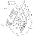
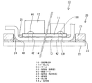
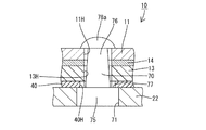
本実施形態の電気接続箱は、回路構成体10を放熱機能を有するケース20内に収容し、ケース20の金属製の放熱板22(本発明の構成要件である放熱部)と回路構成体10とを電気的に絶縁した状態で結合したものである。
In the electrical junction box of the present embodiment, the
回路構成体10は、制御回路基板11と、制御回路基板11の表面(上面)側に実装されて制御回路基板11によって制御されるスイッチング部材12(例えば機械式リレースイッチ、半導体スイッチング素子など)と、制御回路基板11の裏面(下面)に沿って配されて電源に接続される金属板材からなるバスバー13(電力用導電路)とから構成される。
The
制御回路基板11とバスバー13は、制御回路基板11にスイッチング部材12を実装する前の工程で、絶縁性を有する薄い粘着シート14を介して一体化されている。このとき、スイッチング部材12は実装されていないので、制御回路基板11の表面のほぼ全域に亘って均一にプレス機等で押圧することにより、粘着シート14を制御回路基板11の下面(裏面)とバスバー13の上面(表面)に対して強固に接着させることができ、この全面押圧によって制御回路基板11とバスバー13が強固に結合されている。かかる回路構成体10には、制御回路基板11とバスバー13を同軸状に上下方向(制御回路基板11の板面と直角な方向)に貫通する円形の係止孔11H,13Hが、適宜位置(スイッチング部材12が配置されていない位置)に複数形成されている。
The
ケース20は、合成樹脂製の枠体21と、熱伝導率の高い金属製(例えば、アルミニウム合金)の放熱板22とから構成されている。枠体21は、制御回路基板11の外形に沿った形状であって、全周に亘って切れ目無く連続して制御回路基板11を包囲するようになっている。放熱板22は、枠体21の外形と概ね同じ形状とされ、枠体21に対してその下面側から組み付けられるようになっている。また、枠体21と放熱板22との間にはシール層23が形成されている。シール層23は、枠体21の下面側の放熱板22との対向面の全周に亘ってシール材を塗布してから放熱板22で挟みこんで硬化させることで形成され、枠体21と放熱板22とに対し全周に亘って切れ目無く連続して密着している。
枠体21の下面にシール層23を挟みこむように放熱板22を配し、下から放熱板22を貫通させたビスを枠体21の下面に螺合して締め付けると、枠体21と放熱板22とがシール層23を介して一体化されてケース20が構成される。ケース20の内部には、放熱板22と放熱板22の外周に沿って立ち上がる形態の枠体21とにより、上面側に開放された収容空間24が形成される。また、枠体21と放熱板22との隙間はシール層23によって液密状にシールされるため、外部からの水等の浸入が規制されるとともに、収容空間24内の液体が放熱板22と枠体21との隙間を通ってケース20の外部へ流出することが規制される。
The
When the
ケース20の組付けは、ケース20に対する回路構成体10の組付けと平行して行われる。即ち、組付けに際しては、まず、枠体21に対して上から回路構成体10が嵌め込まれ、ビス止めにより回路構成体10と枠体21とが固着(合体)される。その後、枠体21の下面にシール層23を形成し、ビスにより放熱板22と枠体21を固着する。このようにしてケース20と回路構成体10を組み付けた状態では、バスバー13のうち制御回路基板11の下面側に配されている部分が、ケース20の収容空間24内に収容された状態となる。そして、この収容空間24内には防水手段としてポッティング剤25が充填され、このポッティング剤25の内部にバスバー13が埋設された状態となる。
The assembly of the
また、枠体21には上からカバー30が組み付けられ、このカバー30によって回路構成体10の上面側が覆い隠される。さらに、カバー30の前端部には、バスバー13のうちカバー30の前縁から前方へ突出する端子部を包囲する前部コネクタハウジング31が組み付けられ、カバー30の後端縁部にはヒューズボックス32が組み付けられ、このヒューズボックス32には、カバー30の後端縁から上方へ突出する端子部を収容する後部コネクタハウジング33が組み付けられている。
A
放熱板22は、回路構成体10に通電したときにスイッチング部材12などで発生する熱をバスバー13を介して外部に放出する手段として設けられている。放熱効率を高めるためには、バスバー13と放熱板22とを接触させればよいのであるが、放熱板22は金属製であるため、放熱板22は、バスバー13から電気的に絶縁した状態、即ちバスバー13とは接触しない状態を保たなければならない。つまり、放熱効率と絶縁性を両立させるために、放熱板22とバスバー13を非接触であり且つ広い面積に亘って極力接近した位置関係にする必要がある。
The
そこで本実施形態では、バスバー13の下面と放熱板22の上面との間に、電気的絶縁性を有する薄い絶縁シート40を挟み込むことで、放熱板22とバスバー13との間が電気的に絶縁された状態に保たれるようにしている。
Therefore, in the present embodiment, a thin insulating
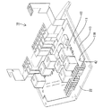
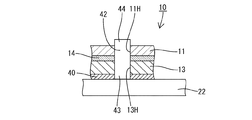
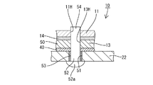
さらに、放熱板22とバスバー13との間隔を極力狭める手段として、放熱板22とバスバー13が離間規制状態に保持する複数の保持体42が設けられている。この保持体42は、合成樹脂製であって、円柱形をなし、放熱板22の上面(収容空間24に臨む面)に対し上方へ突出する形態で固着されている。保持体42の位置としては、枠体21(シール層23)よりも内側の位置(制御回路基板11におけるスイッチング部材12やプリント配線が配置されていない領域)が設定されている。
Further, as a means for narrowing the distance between the
保持体42を放熱板22に固着させる手段としては、予め、保持体42を円柱形に成形しておき、この保持体42の基端部43(下端部)の下端面を、熱溶着、超音波溶着、振動溶着などの手段により溶融状態にして密着させることで放熱板22の上面に溶着(融着)させる方法がある。また、別の手段としては、上下方向に貫通する円形孔を有する金型(図示せず)を表面処理(細かい凹凸や爪を形成する処理)済みの放熱板22の上面に密着させ、その円形孔内に溶融樹脂を高圧で射出して硬化させ、加圧により樹脂を放熱板22の表面の微細な凹凸に食い込ませることで固着する方法もある。
As a means for fixing the holding
このように基端部43において放熱板22と一体化された保持体42は、回路構成体10に係止されるのであるが、制御回路基板11における各保持体42と対応する位置は、夫々、上下方向に貫通する円形の係止孔11H,13Hが形成されている。貫通孔の形成位置にバスバー13が存在している場合には、バスバー13にも係止孔11H,13Hが貫通して形成されている。回路構成体10を放熱板22に対して上から組み付けつつ、各係止孔11H,13Hを保持体42に嵌合させる。この嵌合により回路構成体10が放熱板22に対して水平方向に位置決めされる。
Thus, the holding
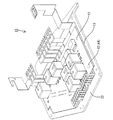
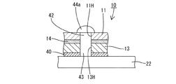
そして、回路構成体10を放熱板22側へ押圧しつつ、係止孔11H,13Hから上方に突出した保持体42の上端の係止部44をプレスにより伏椀形(球面形)に拡径変形させる。この係止部44を拡径変形させるプレス工程に際しては、保持体42の材質に応じて温度管理される。例えば、保持体42の材質がポリプロピレン(PP)等の場合には常温下で拡径変形が行われ、保持体42の材質がポリブチレンテレフタレート(PBT)等の場合には保持体42を加熱した状態で拡径変形が行われる。また、係止部44を拡径変形させる際には、制御回路基板11を放熱板22側(下方)へ押圧する。このプレス工程によって形成された拡径部44aが、制御回路基板11の上面における係止孔11Hの孔縁に係止する状態、いわゆるリベットカシメ状態となって回路構成体10に固着される。尚、本実施形態では、PBTにガラスを30〜40%含有させることで耐熱性を向上させた保持体42が用いられている。
Then, while pressing the
この保持体42の係止部44による係止作用により、回路構成体10が放熱板22に対して上方へ相対変位することが規制される。これにより、回路構成体10と放熱板22とが、絶縁シート40の厚さ分に相当する僅かな間隔を空け、且つ上下方向への離間を規制された状態に結合される。
Due to the locking action of the locking
尚、図3〜図5においては、便宜上、枠体21とシール層23の図示を省略しているが、回路構成体10は枠体21と合体した状態で放熱板22に固着される。また、放熱板22と枠体21とを結合させる工程は、回路構成体10と放熱板22の合体工程の前に行ってもよく、後に行ってもよい。また、本実施形態とは異なり、枠体21が回路構成体10に対して上から被せるように組み付けられる形態である場合には、回路構成体10と放熱板22とを結合した後に、枠体21を回路構成体10に組み付けるようにしてもよい。
3 to 5, for the sake of convenience, the
上述のように本実施形態においては、回路構成体10とケース20の放熱板22とは、保持体42の係止部44の係止作用によって離間規制された状態で結合されるのであるが、回路構成体10と放熱板22との結合に際しては、接着剤を用いた場合のような乾燥のための養生時間が不要なので、作業効率が良い。
As described above, in the present embodiment, the
また、保持体42は合成樹脂製であり、その保持体42の基端部43が、溶融状態で放熱板22に密着することで放熱板22に固着されるようにしたので、放熱板22に貫通形態の孔を形成する必要がない。したがって、放熱板22には、ケース20内に充填したポッティング剤25の漏出対策を講じる必要がなくて済む。
Further, the holding
また、保持体42を回路構成体10に係止する際には、保持体42の係止部44を、回路構成体10の係止孔11H,13Hに貫通させ、その貫通部分をプレスにより拡径変形させて係止孔11Hの孔縁に係止させるようにしたので、係止工程に要する時間が短くて済む。
Further, when the holding
<実施形態2>
次に、本発明を具体化した実施形態2を図9ないし図12を参照して説明する。本実施形態2は、放熱板22に対する保持体50の固着手段を上記実施形態1とは異なる構成としたものである。その他の構成については上記実施形態1と同じであるため、同じ構成については、同一符号を付し、構造、作用及び効果の説明は省略する。
<Embodiment 2>
Next, a second embodiment of the present invention will be described with reference to FIGS. In the second embodiment, the means for fixing the holding
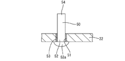
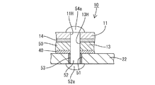
放熱板22には、円形の貫通孔51が形成され、この貫通孔51には、円柱形をなす合成樹脂製の保持体50の基端部52(下端部)が貫通されている。基端部52における放熱板22よりも下方(外側)へ突出した部分は、プレスにより伏椀形に拡径変形させられ、この拡径部52aが放熱板22の下面における貫通孔51の孔縁に係止されている(図10を参照)。また、貫通孔51の内周と保持体50の外周との隙間には防水用の接着剤53(本発明の構成要件であるシール手段)が注入されており、この接着剤53により、貫通孔51における液体(ケース20の収容空間24内に充填されるポッティング材25)の通過が防止される。以上により、保持体50の基端部52が放熱板22に固着される。
A circular through
この後、回路構成体10の係止孔11H,13Hが保持体50に嵌合され、保持体50の上端の係止部54が回路構成体10の上面から上方へ突出した状態となる(図11を参照)。この係止部54の突出部分をプレスにより伏椀形に拡径変形させることで、その拡径部54aが制御回路基板11の上面における係止孔11Hの孔縁に係止し、もって、保持体50が回路構成体10に固着される(図12を参照)。
Thereafter, the locking
本実施形態2においては、基端部52を拡径変形させて放熱板22の貫通孔51の孔縁に対して下から係止するようになっているので、保持体50に上向きの力が付与されても、保持体50の基端部52は確実に放熱板22に固着された状態に保たれる。また、係止部54は、その拡径部54aを係止孔11Hの孔縁に対して上から係止させているので、保持体50に下向きに力が付与されても、保持体50の係止部54は確実に回路構成体10に固着された状態に保たれる。このように、回路構成体10と放熱板22は、保持体50の上下両端の拡径部54a,52aの間で挟み付けられているので、上下に離間する虞はない。
In the second embodiment, the
<実施形態3>
次に、本発明を具体化した実施形態3を図13及び図14を参照して説明する。本実施形態3は、放熱板22に対する保持体60の固着手段を上記実施形態1とは異なる構成としたものである。その他の構成については上記実施形態1と同じであるため、同じ構成については、同一符号を付し、構造、作用及び効果の説明は省略する。
<Embodiment 3>
Next, a third embodiment of the present invention will be described with reference to FIGS. In the third embodiment, the fixing means of the holding
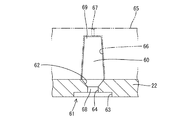
本実施形態3では、保持体60を型内融着により放熱板22に固着するが、前処理として、放熱板22に貫通孔61が形成されている。この貫通孔61の上端部(ケース20の収容空間24側の端部)には、上方(収容空間24側)に向かって拡径するすり鉢状(円錐状)をなす円形のテーパ孔62が形成され、貫通孔61の下端部には、テーパ孔62よりも大径で且つテーパ孔62と同心の円形をなす大径孔63が形成され、テーパ孔62と大径孔63との間には、大径孔63よりも小径で且つテーパ孔62の最小径と同径の小径孔64がテーパ孔62及び大径孔63と同心の円形状に形成されている。
In the third embodiment, the holding
貫通孔61が形成された放熱板22は図示しない下型に載置され、放熱板22の上面には、貫通孔61と整合する成形孔66が形成された上型65が載置される。そして、ゲート67から成形孔66内及び貫通孔61内に溶融樹脂を高圧で射出する。射出された溶融樹脂が硬化すると、保持体60が成形されるとともにその基端部68が貫通孔61内に充填された状態となり、硬化後に型開きすれば、放熱板22に対し保持体60が上方へ突出した形態で固着される。貫通孔61内の基端部68は小径孔64において絞られた形態となっているので、上下いずれの方向へ保持体60が引っ張られても、基端部68におけるテーパ孔62への充填部と大径部63への充填部が引っ掛かりとなり、保持体60は放熱板22に対して上下方向へ相対変位することはない。
The
また、射出成形の際には、射出圧によって溶融樹脂が貫通孔61の内周面に隙間なく密着するので、基端部68の外周面と貫通孔61の内周面と間に隙間が生じることはなく、別途シール手段を設けなくても、信頼性の高い防水機能が得られる。尚、保持体60のうち放熱板22から上方へ突出した部分は、上方に向かって縮径するようにテーパ状をなしているが、これは、成形孔66からの型抜きが円滑に行われるようにするための手段として講じられた形状である。また、貫通孔61内では、保持体60の基端部68が成形孔66の小径孔64において機械的に引っ掛かる形状を呈しているため、貫通孔61の内周面に微細な凹凸や爪形状を形成するための表面処理は不要である。
Further, at the time of injection molding, the molten resin adheres closely to the inner peripheral surface of the through
保持体60の上端の係止部69は、上記実施形態1と同様に、回路構成体10の係止孔11Hに貫通され、その貫通部分をプレスにより拡径変形させることで、図14に示すように、拡径部69aが制御回路基板11の上面における係止孔11Hの孔縁に係止する。これにより、係止部69が回路構成体10に固着される。
As shown in FIG. 14, the locking
<実施形態4>
次に、本発明を具体化した実施形態4を図15及び図16を参照して説明する。本実施形態4は、放熱板22に対する保持体70の固着手段を上記実施形態1とは異なる構成としたものである。その他の構成については上記実施形態1と同じであるため、同じ構成については、同一符号を付し、構造、作用及び効果の説明は省略する。
<Embodiment 4>
Next, a fourth embodiment of the present invention will be described with reference to FIGS. In the fourth embodiment, the means for fixing the holding
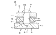
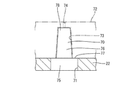
本実施形態4では、実施形態3と同様に、保持体70を型内融着により放熱板22に固着したものであり、前処理として、放熱板22に貫通孔71が形成されている。この貫通孔71は上下方向(貫通方向)において、内径が一定の円形をなしている。尚、この貫通孔71の内周面には、微細や凹凸や爪を形成するための表面処理を施しておくことが好ましい。
In the fourth embodiment, similarly to the third embodiment, the holding
貫通孔71が形成された放熱板22は図示しない下型に載置され、放熱板22の上面には、貫通孔71と整合する成形孔73が形成された上型72が載置される。この成形孔73の内径は貫通孔71よりも径が小さい。ゲート74から成形孔73内及び貫通孔71内に溶融樹脂が高圧で射出され、射出された溶融樹脂が硬化すると、保持体70が成形されるとともにその基端部75が貫通孔71内に充填される。この後、硬化後に型開きすれば、放熱板22に対し保持体70が上方へ突出した形態で固着される。
The
貫通孔71の内周面には保持体70の基端部75が強固に密着するため、保持体70が放熱板22に対して上下方向へ相対変位することはない。また、射出成形の際には、射出圧によって溶融樹脂が貫通孔71の内周面に隙間なく密着するので、基端部75の外周面と貫通孔71の内周面と間に隙間が生じることはなく、別途シール手段を設けなくても、信頼性の高い防水機能が得られる。
Since the
保持体70のうち放熱板22から上方へ突出した部分76は、基端部75よりも小径で且つ基端部75と同心状の略円柱形(詳細には、上方に向かって縮径するようにテーパ状)をなす。つまり、基端部75と基端部75よりも上方の部分76(放熱板22の上面から突出した部分)との境界では段差状に径寸法が変位する形態とされている。そして、この段差形状により形成された基端部75の円環状をなす上面は、放熱板22の上面に対して面一状に連続する絶縁面77となっている。
A
一方、放熱板22の上面と回路構成体10のバスバー13の下面との間に挟み込まれる絶縁シート40には、バスバー13や制御回路基板11の係止孔11H,13Hと対応する係止孔40Hが形成されているのであるが、上記した絶縁面77は、図16に示すように、絶縁シート40の係止孔40Hの内径寸法がバスバー13の係止孔13Hの内径よりも大きくなった場合に有効に作用する。即ち、絶縁シート40の係止孔40Hの内径が大きい場合、バスバー13における係止孔13Hの孔縁部が、絶縁シート40の係止孔40Hの孔縁よりも内側へ張り出して放熱板22と接触することが懸念される。
On the other hand, the insulating
しかし、本実施形態では、放熱板22の貫通孔71の内径が絶縁シート40の係止孔40Hよりも大きくなるようにして、貫通孔71の内側では、絶縁シート40における係止孔40Hの孔縁部とバスバー13における係止孔13Hの孔縁部が、保持体70の基端部75の絶縁面77と対応するようにしている。これにより、絶縁シート40の係止孔40Hがバスバー13の係止孔13Hよりも径が大きい場合でも、バスバー13における係止孔13Hの孔縁部が、放熱板22とは直接対応せずに、樹脂製の絶縁面77と対応するようになり、バスバー13と放熱板22との接触を確実に回避することができるようになっている。
However, in the present embodiment, the inner diameter of the through
尚、保持体70の上端の係止部78は、上記実施形態3と同様に、回路構成体10の係止孔11H,13Hから上方に貫通され、その貫通部分をプレスにより拡径変形させることで、図16に示すように、拡径部78aが制御回路基板11の上面における係止孔11Hの孔縁に係止し、これにより、係止部78が回路構成体10に固着される。
In addition, the latching | locking
<他の実施形態>
本発明は上記記述及び図面によって説明した実施形態に限定されるものではなく、例えば次のような実施態様も本発明の技術的範囲に含まれ、さらに、下記以外にも要旨を逸脱しない範囲内で種々変更して実施することができる。
<Other embodiments>
The present invention is not limited to the embodiment described with reference to the above description and drawings. For example, the following embodiments are also included in the technical scope of the present invention, and further, within the scope not departing from the gist of the invention other than the following. Various modifications can be made.
(1)上記実施形態ではケース内にポッティング材を充填して回路構成体を防水するようにしたが、本発明によれば、ポッティング材の充填に替えて、ケースの開口部に防水性を有するカバーを被せてもよい。 (1) In the above-described embodiment, the potting material is filled in the case to waterproof the circuit structure. However, according to the present invention, the opening of the case is waterproof instead of filling the potting material. A cover may be put on.
(2)上記実施形態ではケース内の回路構成体を防水する手段を設けたが、本発明は、非防水タイプのものにも適用できる。 (2) In the above embodiment, means for waterproofing the circuit structure in the case is provided, but the present invention can also be applied to a non-waterproof type.
(3)上記実施形態では回路構成体を構成する電力用導電路がバスバーである場合について説明したが、本発明によれば、電力用導電路が制御回路基板に密着させて設けた厚膜回路であってもよい。 (3) In the above embodiment, the case where the power conductive path constituting the circuit structure is a bus bar has been described, but according to the present invention, the thick film circuit in which the power conductive path is provided in close contact with the control circuit board. It may be.
(4)上記実施形態ではケースが防水壁と放熱部材との2部品で構成されているが、本発明によれば、ケースが防水壁と放熱部材とを一体化させたワンピース部品であってもよい。 (4) In the above embodiment, the case is composed of two parts, a waterproof wall and a heat radiating member. However, according to the present invention, even if the case is a one-piece part in which the waterproof wall and the heat radiating member are integrated. Good.
(5)上記実施形態では保持手段が回路構成体とケースのいずれからも独立した部品であったが、本発明によれば、保持手段が回路構成体とケースのうちのいずれか一方又は両方に一体形成された金属製のものであってもよい。この場合、例えば、アルミダイキャスト製法で保持手段をケースに一体に形成することができる。 (5) In the above embodiment, the holding means is a component independent from both the circuit structure and the case. However, according to the present invention, the holding means is provided in either one or both of the circuit structure and the case. An integrally formed metal may be used. In this case, for example, the holding means can be integrally formed with the case by an aluminum die casting method.
10…回路構成体
11H…係止孔
20…ケース
22…放熱板(放熱部)
40…絶縁シート
42…保持体(保持手段)
43…基端部
44…係止部
44a…拡径部
50,60,70…保持体(保持手段)
51…貫通孔
52,68,75…基端部
52a…基端部の拡径部
54,69,78…係止部
54a,69a,78a…係止部の拡径部
DESCRIPTION OF
40 ... Insulating
43 ...
51 ... Through
Claims (4)
電気的絶縁性を有し、前記回路構成体と前記放熱部との間に挟まれる絶縁シートと、
前記回路構成体と前記ケースのうちいずれか一方に対し基端部が一体化されるとともに、先端部に係止部が形成された形態の保持手段を設け、
前記回路構成体と前記ケースのうち他方に前記係止部を係止させることで、前記回路構成体と前記放熱部とを離間規制状態に結合したことを特徴とする電機接続箱。 In the case where the circuit structure is housed in a case having a heat dissipation function, and the metal heat dissipation portion of the case and the circuit structure are coupled in an electrically insulated state,
An insulating sheet having electrical insulation and sandwiched between the circuit component and the heat dissipating part;
A base end portion is integrated with respect to any one of the circuit component and the case, and a holding means in a form in which a locking portion is formed at a distal end portion is provided,
An electric junction box characterized in that the circuit component and the heat dissipating part are coupled in a separation restricted state by locking the locking part to the other of the circuit component and the case.
前記基端部が、溶融状態で前記放熱部に密着することで前記放熱部に固着されていることを特徴とする請求項1記載の電気接続箱。 The holding means is made of synthetic resin;
The electrical junction box according to claim 1, wherein the base end portion is fixed to the heat radiating portion by being in close contact with the heat radiating portion in a molten state.
前記基端部が、前記放熱部に形成した貫通孔に貫通されるとともに、その貫通部分を拡径変形させて前記貫通孔の孔縁に係止させることで前記ケースに固着され、
前記基端部の拡径部と前記貫通孔の孔縁との隙間がシール手段によりシールされていることを特徴とする請求項1記載の電気接続箱。 The holding means is made of synthetic resin;
The base end is fixed to the case by penetrating through a through-hole formed in the heat-dissipating part, and expanding the diameter of the penetrating part and engaging with the hole edge of the through-hole,
The electrical junction box according to claim 1, wherein a gap between the enlarged diameter portion of the base end portion and a hole edge of the through hole is sealed by a sealing means.
前記係止部が、前記回路構成体に形成した係止孔に貫通されるとともに、その貫通部分を拡径変形させて前記係止孔の孔縁に係止させることで前記回路構成体に固着されていることを特徴とする請求項1ないし請求項3のいずれかに記載の電気接続箱。 The holding means is made of synthetic resin;
The locking portion is penetrated through a locking hole formed in the circuit structure, and the through-hole is expanded and deformed so as to be locked to a hole edge of the locking hole. The electrical junction box according to any one of claims 1 to 3, wherein the electrical junction box is provided.
Priority Applications (1)
| Application Number | Priority Date | Filing Date | Title |
|---|---|---|---|
| JP2004111173A JP2005294741A (en) | 2004-04-05 | 2004-04-05 | Electrical junction box |
Applications Claiming Priority (1)
| Application Number | Priority Date | Filing Date | Title |
|---|---|---|---|
| JP2004111173A JP2005294741A (en) | 2004-04-05 | 2004-04-05 | Electrical junction box |
Publications (1)
| Publication Number | Publication Date |
|---|---|
| JP2005294741A true JP2005294741A (en) | 2005-10-20 |
Family
ID=35327297
Family Applications (1)
| Application Number | Title | Priority Date | Filing Date |
|---|---|---|---|
| JP2004111173A Pending JP2005294741A (en) | 2004-04-05 | 2004-04-05 | Electrical junction box |
Country Status (1)
| Country | Link |
|---|---|
| JP (1) | JP2005294741A (en) |
Cited By (10)
| Publication number | Priority date | Publication date | Assignee | Title |
|---|---|---|---|---|
| JP2007259594A (en) * | 2006-03-23 | 2007-10-04 | Sumitomo Wiring Syst Ltd | Electrical connection box and manufacturing method therefor |
| JP2010220295A (en) * | 2009-03-13 | 2010-09-30 | Autonetworks Technologies Ltd | Circuit structure and electrical junction box |
| JP2012033549A (en) * | 2010-07-28 | 2012-02-16 | Fdk Twicell Co Ltd | Circuit board device |
| JP2015139289A (en) * | 2014-01-22 | 2015-07-30 | 株式会社オートネットワーク技術研究所 | Switching board |
| JP2016220361A (en) * | 2015-05-19 | 2016-12-22 | 日産自動車株式会社 | Power converter |
| WO2017104517A1 (en) * | 2015-12-16 | 2017-06-22 | 株式会社オートネットワーク技術研究所 | Circuit structure, and electrical connection box |
| WO2017104518A1 (en) * | 2015-12-16 | 2017-06-22 | 株式会社オートネットワーク技術研究所 | Circuit structure, and electrical connection box |
| WO2017145784A1 (en) * | 2016-02-22 | 2017-08-31 | 株式会社オートネットワーク技術研究所 | Circuit structure |
| CN109587949A (en) * | 2019-01-11 | 2019-04-05 | 深圳市南瑞华腾新能源有限公司 | High voltage distribution installation PCB construction and its manufacturing method |
| WO2022260023A1 (en) * | 2021-06-11 | 2022-12-15 | 株式会社オートネットワーク技術研究所 | Circuit assembly |
-
2004
- 2004-04-05 JP JP2004111173A patent/JP2005294741A/en active Pending
Cited By (17)
| Publication number | Priority date | Publication date | Assignee | Title |
|---|---|---|---|---|
| JP2007259594A (en) * | 2006-03-23 | 2007-10-04 | Sumitomo Wiring Syst Ltd | Electrical connection box and manufacturing method therefor |
| JP2010220295A (en) * | 2009-03-13 | 2010-09-30 | Autonetworks Technologies Ltd | Circuit structure and electrical junction box |
| JP2012033549A (en) * | 2010-07-28 | 2012-02-16 | Fdk Twicell Co Ltd | Circuit board device |
| JP2015139289A (en) * | 2014-01-22 | 2015-07-30 | 株式会社オートネットワーク技術研究所 | Switching board |
| JP2016220361A (en) * | 2015-05-19 | 2016-12-22 | 日産自動車株式会社 | Power converter |
| JP2017112196A (en) * | 2015-12-16 | 2017-06-22 | 株式会社オートネットワーク技術研究所 | Circuit structure, and electric connection box |
| WO2017104518A1 (en) * | 2015-12-16 | 2017-06-22 | 株式会社オートネットワーク技術研究所 | Circuit structure, and electrical connection box |
| JP2017112708A (en) * | 2015-12-16 | 2017-06-22 | 株式会社オートネットワーク技術研究所 | Circuit structure and electrical junction box |
| WO2017104517A1 (en) * | 2015-12-16 | 2017-06-22 | 株式会社オートネットワーク技術研究所 | Circuit structure, and electrical connection box |
| US10576912B2 (en) | 2015-12-16 | 2020-03-03 | Autonetworks Technologies, Ltd. | Circuit assembly and electrical junction box |
| DE112016005794B4 (en) | 2015-12-16 | 2022-05-25 | Autonetworks Technologies, Ltd. | Circuit arrangement and electrical junction box |
| WO2017145784A1 (en) * | 2016-02-22 | 2017-08-31 | 株式会社オートネットワーク技術研究所 | Circuit structure |
| CN109587949A (en) * | 2019-01-11 | 2019-04-05 | 深圳市南瑞华腾新能源有限公司 | High voltage distribution installation PCB construction and its manufacturing method |
| WO2022260023A1 (en) * | 2021-06-11 | 2022-12-15 | 株式会社オートネットワーク技術研究所 | Circuit assembly |
| JP2022189500A (en) * | 2021-06-11 | 2022-12-22 | 株式会社オートネットワーク技術研究所 | Circuit structure |
| CN117397375A (en) * | 2021-06-11 | 2024-01-12 | 株式会社自动网络技术研究所 | circuit structure |
| JP7606676B2 (en) | 2021-06-11 | 2024-12-26 | 株式会社オートネットワーク技術研究所 | Circuit structure |
Similar Documents
| Publication | Publication Date | Title |
|---|---|---|
| JP4377919B2 (en) | Electrical junction box | |
| CN112585832B (en) | Electrical connection box | |
| JP4114497B2 (en) | CASE FOR CIRCUIT COMPOSITE AND METHOD FOR MANUFACTURING CIRCUIT COMPOSITION | |
| CN110662372A (en) | Electronic unit and method for manufacturing the same | |
| US10381243B2 (en) | Semiconductor module having supporting portion for fastening portion inside a through hole in a resin case | |
| JP2005294741A (en) | Electrical junction box | |
| CN107251347A (en) | circuit structure and electric connection box | |
| US20160183405A1 (en) | Electronic device and method for manufacturing the electronic device | |
| JPH10116962A (en) | Semiconductor device and manufacturing method thereof | |
| JP2019021667A (en) | CIRCUIT DEVICE, CIRCUIT DEVICE MANUFACTURING METHOD, AND CONNECTOR | |
| WO2016035600A1 (en) | Circuit structure, electrical junction box, and spacer | |
| JP2017102338A (en) | On-vehicle camera | |
| JP2021048268A (en) | Manufacturing method of circuit unit, electrical junction box and circuit unit | |
| JP2008258103A (en) | Mold connector and its manufacturing method | |
| JP2012134300A (en) | Semiconductor device | |
| WO2022260023A1 (en) | Circuit assembly | |
| JP2009033170A (en) | Power semiconductor module having sealing mechanism for substrate carrier and manufacturing method thereof | |
| JP2006027183A (en) | Metal-resin composite and method for producing the same | |
| JP2006005107A (en) | Circuit structure | |
| CN108141976B (en) | Housing, semiconductor device, and manufacturing method of housing | |
| JP4228955B2 (en) | Electrical junction box | |
| JP5325487B2 (en) | Power semiconductor module having connected substrate carrier and method for manufacturing the same | |
| JP2006271132A (en) | Electric junction box fixing structure for automobiles | |
| JP2008060512A (en) | Terminal box for solar cell module | |
| JPH09260103A (en) | Mounting structure of PTC element to electrical junction box |