JP2005294583A - Transmissive radio wave absorbing member - Google Patents
Transmissive radio wave absorbing member Download PDFInfo
- Publication number
- JP2005294583A JP2005294583A JP2004108448A JP2004108448A JP2005294583A JP 2005294583 A JP2005294583 A JP 2005294583A JP 2004108448 A JP2004108448 A JP 2004108448A JP 2004108448 A JP2004108448 A JP 2004108448A JP 2005294583 A JP2005294583 A JP 2005294583A
- Authority
- JP
- Japan
- Prior art keywords
- electromagnetic wave
- conductive material
- density
- transmission
- wave absorbing
- Prior art date
- Legal status (The legal status is an assumption and is not a legal conclusion. Google has not performed a legal analysis and makes no representation as to the accuracy of the status listed.)
- Withdrawn
Links
Images

Landscapes
- Shielding Devices Or Components To Electric Or Magnetic Fields (AREA)
Abstract
Description
本発明は、アンテナなどに使用される透過型の電磁波吸収材に関するものである。 The present invention relates to a transmission type electromagnetic wave absorber used for an antenna or the like.
電磁波を利用したアンテナ間通信において、電磁波は伝播距離が長いと減衰してしまうため、適正な通信環境を確保するためには、出力や入力を調整する必要がある。例えば、アンテナ間距離が短い場合は伝播による減衰が小さいため、送信アンテナの出力レベルを小さくするが、アンテナ間距離が長い場合は、送信アンテナの出力レベルを大きくしたり、受信アンテナの感度を高くする必要が生じる。一般的には、このような調整はアンテナ装置(送受信機器側)によって行われる。 In inter-antenna communication using electromagnetic waves, electromagnetic waves are attenuated when the propagation distance is long. Therefore, in order to ensure an appropriate communication environment, it is necessary to adjust output and input. For example, if the distance between antennas is short, the attenuation due to propagation is small, so the output level of the transmitting antenna is reduced.If the distance between antennas is long, the output level of the transmitting antenna is increased or the sensitivity of the receiving antenna is increased. Need to do. Generally, such adjustment is performed by an antenna device (transmission / reception equipment side).
しかし、このような調整を可能とするアンテナシステムは高価になる。このため、出力レベルは、一定にしておいて、アンテナ前面に透過型の電磁波吸収材を設置し、電磁波を吸収させることにより減衰させてレベル調整する方法がある。
このような透過型の電磁波吸収材としては、特許文献1に記載されるように、誘電体層とインピーダンス層を備えた構造のものがある。この透過型電磁波吸収材は、誘電体層側から入射する電磁波に対して、透過するような設計が可能であるが、インピーダンス層からの入射に対しては考慮されていない。しかしながら、アンテナシステムに使用するような透過型の電磁波吸収材は、双方向からの電磁波に対して、同様に吸収、透過させることが必要であり、特許文献1のような片面からの入射のみを考慮した吸収材は使用できない。
However, an antenna system that enables such adjustment is expensive. For this reason, there is a method in which the output level is kept constant, a transmission type electromagnetic wave absorber is installed on the front surface of the antenna, and the level is adjusted by attenuation by absorbing the electromagnetic wave.
As such a transmission type electromagnetic wave absorber, there is a structure having a dielectric layer and an impedance layer as described in
本発明は、低密度の多孔質基材に導電性材料を付着させた構造にし、更には、導電材料を均一に付着させることにより、双方向からの電磁波を吸収及び透過させることができる透過型の電磁波吸収材の提供を目的とする。 The present invention has a structure in which a conductive material is attached to a low-density porous base material, and furthermore, a transmission type that can absorb and transmit electromagnetic waves from both directions by uniformly attaching the conductive material. The purpose is to provide an electromagnetic wave absorbing material.
本発明は上記の点に鑑みてなされたものであり、本発明の透過型電磁波吸収材は、請求項1記載の通り、密度が4〜32kg/m3の多孔質基材に導電性材料を付着させ、この導電性材料の付着密度を0.5〜3.5kg/m3としたことを特徴とする。
また、請求項2記載の透過型電磁波吸収材は、請求項1記載の透過型電磁波吸収材において、前記導電性材料は、多孔質基材に均一に付着していることを特徴とする。
また、請求項3記載の透過型電磁波吸収材は、請求項1又は2記載の透過型電磁波吸収材において、前記多孔質基材は、ガラス長繊維からなることを特徴とする。
This invention is made | formed in view of said point, The transmissive | pervious electromagnetic wave absorber of this invention is a conductive material to a porous base material with a density of 4-32 kg / m < 3 > as described in
The transmissive electromagnetic wave absorbing material according to
The transmissive electromagnetic wave absorbing material according to claim 3 is the transmissive electromagnetic wave absorbing material according to
このように、本発明の透過型電磁波吸収材は、低密度の多孔質基材を用いることで、付着させる導電性材料の量を容易に調整することができ、吸収と透過を同時に実現するために必要な、比較的少量の導電性材料の付着が可能となる。
更に、導電性材料を多孔質基材に均一に付着させることで、双方向からの電磁波の入射に対して、同じように吸収と透過の機能を発揮することができる。
また、多孔質基材が低密度であることから軽量化が実現しやすく、設置するアンテナへの負担が小さくてすむとともに、多孔質基材にガラス繊維などの不燃性材料を使用することで、不燃性の実現も可能である。
As described above, the transmission electromagnetic wave absorbing material of the present invention can easily adjust the amount of the conductive material to be attached by using a low-density porous substrate, and realizes absorption and transmission at the same time. It is possible to deposit a relatively small amount of conductive material necessary for the above.
Further, by uniformly adhering the conductive material to the porous base material, the absorption and transmission functions can be exhibited in the same manner with respect to the incidence of electromagnetic waves from both directions.
In addition, since the porous base material has a low density, it is easy to reduce the weight, and the burden on the antenna to be installed can be reduced, and by using a non-combustible material such as glass fiber for the porous base material, Incombustibility can also be realized.
本発明の透過型電磁波吸収材は、多孔質基材に導電性材料を付着させてなるものであるが、この多孔質基材の密度は、4〜32kg/m3が好ましく、5〜10kg/m3がより好ましい。これは、多孔質基材の密度が32kg/m3超であると、多孔質基材の空隙率が小さく、導電性材料を付着させることが難しいからである。また、一般的にこのような多孔質基材に導電性材料を付着させる場合は、多孔質基材を導電性材料が分散した液に浸漬して、その後に取り出して乾燥させる方法が一般的であるが、この工程において、基材密度が32kg/m3超である場合、多孔質基材のなかで導電性材料の移動が徐々に進むため、乾燥時に厚さ方向に付着むらが発生し、均一に導電性材料を付着させることが困難である。32kg/m3以下の低密度であれば、乾燥工程に入る前に、脱水や予備乾燥により、導電性材料の移行をある程度留めることが可能で、乾燥工程中に導電性材料の付着むらが発生しない。また、多孔質基材の密度が4kg/m3未満であると、導電性材料を付着する際に電磁波吸収材の形状保持ができず、多孔質基材がバラバラになる問題がある。 The transmission type electromagnetic wave absorbing material of the present invention is obtained by adhering a conductive material to a porous substrate. The density of this porous substrate is preferably 4 to 32 kg / m 3 , and 5 to 10 kg / m 3 is more preferable. This is because when the density of the porous substrate is more than 32 kg / m 3 , the porosity of the porous substrate is small and it is difficult to attach the conductive material. In general, when a conductive material is attached to such a porous substrate, a method in which the porous substrate is immersed in a liquid in which the conductive material is dispersed, and then taken out and dried is generally used. However, in this process, when the substrate density is more than 32 kg / m 3 , the movement of the conductive material gradually proceeds in the porous substrate, so that uneven adhesion occurs in the thickness direction during drying, It is difficult to deposit the conductive material uniformly. If the density is lower than 32 kg / m 3, the transfer of the conductive material can be stopped to some extent by dehydration or preliminary drying before entering the drying process, and uneven adhesion of the conductive material occurs during the drying process. do not do. Further, when the density of the porous substrate is less than 4 kg / m 3 , there is a problem that the shape of the electromagnetic wave absorbing material cannot be maintained when the conductive material is adhered, and the porous substrate is separated.
このような低密度の多孔質基材は、繊維多孔質板などで実現可能であるが、不燃性を考慮すると無機質繊維多孔質板が好ましく、更には、ガラス長繊維多孔質板が好ましい。前記ガラス長繊維多孔質板は公知の方法により製造可能であり、例えば、既に自動車用電池の絶縁体や、換気扇などのフィルタとして一般的に使用されている。このガラス長繊維多孔質板の特徴は、ガラス短繊維と異なり、繊維が連続していることから、低密度で多孔質基材を実現することができ、更に、エアフィルタのように、長繊維をカール状に加工することによって、低密度でありながら比較的厚い多孔質基材を実現できることにある。 Such a low-density porous substrate can be realized with a fiber porous plate or the like, but in consideration of nonflammability, an inorganic fiber porous plate is preferable, and a glass long fiber porous plate is more preferable. The long glass fiber porous plate can be produced by a known method. For example, the long glass fiber porous plate is already generally used as an insulator for automobile batteries or a filter such as a ventilation fan. The feature of this long glass fiber porous plate is that, unlike the short glass fiber, the fiber is continuous, so that a porous substrate can be realized at a low density. By processing this into a curled shape, it is possible to realize a relatively thick porous substrate with low density.
前記多孔質基材に付着させる導電性材料としては、カーボンブラックやグラファイト、金属系の微粒子などがあるが、取扱い性やコストを勘案すると、カーボンブラック又はグラファイトが好ましい。これら導電性材料を多孔質基材に効率よく付着させるためには、導電性材料を水やアルコールに分散させた状態にしておくことが好ましく、また、多孔質基材に固定させるために、水ガラスなどの無機系や、アクリルなどの有機系バインダを混合するようにしてもよい。 Examples of the conductive material to be attached to the porous substrate include carbon black, graphite, and metal-based fine particles, but carbon black or graphite is preferable in consideration of handling property and cost. In order to efficiently attach these conductive materials to the porous base material, it is preferable to keep the conductive material dispersed in water or alcohol, and in order to fix the conductive material to the porous base material, An inorganic binder such as glass or an organic binder such as acrylic may be mixed.
多孔質基材に導電性材料を付着させるためには、前記のように導電性材料を分散させた液に多孔質基材を浸漬させて、取り出し、その後、乾燥させる方法がある。尚、電磁波吸収特性と透過特性は、多孔質基材への導電性材料の付着量、つまりは多孔質基材の体積抵抗値によって決まる。また、導電性材料の付着量の調整は、導電性材料の分散液の固形分濃度の調整によって比較的容易にできる。導電性材料の付着密度は、0.5〜3.5kg/m3が好ましい。0.5kg/m3未満であれば、反射も吸収も小さく、透過量を調整することができない。3.5kg/m3超であれば、反射と吸収が多くなり、透過量が小さくなってしまう。尚、入射した電磁波は、電磁波吸収材の表面で反射されるもの、内部で吸収されるもの及び透過するものがあり、それらの量は以下のように表せる。
入射する電磁波量=反射量+吸収量+透過量
透過型の電磁波吸収材は、透過量を調整することが目的であることから、この反射量と吸収量を調整すればよいことになる。透過量を大きくする場合は、導電性材料の付着密度を小さくして、吸収と反射量を小さくする必要がある。また、透過量を小さくする場合は、導電性材料の付着密度を大きくして、吸収量を大きくする必要がある。しかしこの場合、反射量が大きくなると、反射波はアンテナ側に戻るため、アンテナから発信される電磁波と反射波で干渉がおこり、通信エラーの原因となることがある。従って、できるだけ反射量を小さくして、吸収することによって透過量を調整すること好ましい。
In order to attach the conductive material to the porous base material, there is a method in which the porous base material is dipped in the liquid in which the conductive material is dispersed as described above, taken out, and then dried. The electromagnetic wave absorption characteristics and transmission characteristics are determined by the amount of the conductive material attached to the porous substrate, that is, the volume resistance value of the porous substrate. Moreover, the adjustment of the adhesion amount of the conductive material can be made relatively easy by adjusting the solid content concentration of the dispersion liquid of the conductive material. The adhesion density of the conductive material is preferably 0.5 to 3.5 kg / m 3 . If it is less than 0.5 kg / m 3 , reflection and absorption are both small, and the amount of transmission cannot be adjusted. If it exceeds 3.5 kg / m 3 , reflection and absorption increase, and the transmission amount decreases. Incident electromagnetic waves include those that are reflected on the surface of the electromagnetic wave absorber, those that are absorbed inside, and those that are transmitted, and their amounts can be expressed as follows.
Incident electromagnetic wave amount = reflection amount + absorption amount + transmission amount Since the transmission type electromagnetic wave absorbing material is intended to adjust the transmission amount, the reflection amount and the absorption amount may be adjusted. When increasing the amount of transmission, it is necessary to reduce the adhesion density of the conductive material to reduce the amount of absorption and reflection. Further, when reducing the transmission amount, it is necessary to increase the adhesion density of the conductive material and increase the absorption amount. However, in this case, when the amount of reflection increases, the reflected wave returns to the antenna side, so that interference may occur between the electromagnetic wave transmitted from the antenna and the reflected wave, which may cause a communication error. Therefore, it is preferable to adjust the transmission amount by making the amount of reflection as small as possible and absorbing.
このような透過型の電磁波吸収材は、アンテナ用として屋外での使用が多い。したがって、耐候性の観点や、雨などが基材内へ進入することを防ぐために、透過型の電磁波吸収材の表面及び全面をシートで覆うようにしてもよい。このようなシートとしては、厚さ1mm以下の樹脂シートであれば、電磁波の吸収及び透過機能に大きく影響することはない。樹脂シートとしては、耐候性に優れたポリフッ化ビニールシートなどがある。ポリフッ化ビニールシートは、熱融着加工も可能であることから、2枚のポリフッ化ビニールシートで透過型の電磁波吸収材を挟み込み、四辺を熱融着することで、密封することも可能である。 Such transmissive electromagnetic wave absorbers are often used outdoors for antennas. Accordingly, the surface and the entire surface of the transmission type electromagnetic wave absorbing material may be covered with a sheet in order to prevent the weather resistance and rain from entering the base material. If such a sheet is a resin sheet having a thickness of 1 mm or less, the absorption and transmission functions of electromagnetic waves are not greatly affected. Examples of the resin sheet include a polyvinyl fluoride sheet having excellent weather resistance. Since the polyvinyl fluoride sheet can be heat-sealed, it can be sealed by sandwiching a transmission type electromagnetic wave absorbing material between two polyvinyl fluoride sheets and heat-sealing the four sides. .
次に本発明の透過型電磁波吸収材の実施例を図面に基づき説明する。 Next, examples of the transmission type electromagnetic wave absorbing material of the present invention will be described with reference to the drawings.
(実施例1)
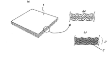
図1(a)は、本発明の透過型電磁波吸収材の多孔質基材となる、平均繊維径20μm、厚さ25mm、密度6kg/m3、寸法500mm×500mmのガラス長繊維多孔質板1の全体斜視図を示し、図1(b)は、図1(a)の部分拡大断面図を示す。
図中1で示されるガラス長繊維多孔質板の重量は32gであった。このガラス長繊維多孔質板1は日本無機(株)製のコスモ(r)フィルタであり、一般にはフィルタとして使用されているものである。
次に、重量比で、水:グラファイト:水ガラスをそれぞれ97:2:1の割合で混同した分散液を準備した。この分散液に前記ガラス長繊維多孔質板1を浸漬させた後、取り出し、水平にして1分間放置させた。この間、グラファイト分散液は、ガラス長繊維多孔質板1の厚さ方向の下側に移行し、最後には多孔質板から脱落するが、分散液が低粘度であることと、基材が超低密度であるため、この時に多孔質板の厚さ方向にグラファイト分散液の付着むらはできない。1分間の放置後、雰囲気温度が130℃の乾燥機内で10分間放置して、ガラス長繊維多孔質板1の全体に導電性材料のグラファイト3を付着させて、図1(c)に、部分拡大図を示すように、グラファイト付着ガラス長繊維多孔質板2を作成した。このときのグラファイト付着ガラス長繊維多孔質板2の重量は42gであり、グラファイトの付着密度は1.6kg/m3であった。
(Example 1)
FIG. 1 (a) shows a glass long fiber
The weight of the long glass fiber porous plate indicated by 1 in the figure was 32 g. This long glass fiber
Next, a dispersion liquid in which water: graphite: water glass was confused at a weight ratio of 97: 2: 1 was prepared. The long glass fiber
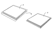
こうして製作したグラファイト付着ガラス長繊維多孔質板2を、図2に示すように、厚さが20μmのポリフッ化ビニールシート4で挟み込み、四辺を熱融着により圧着して密封して、透過型電磁波吸収材5を得た。
As shown in FIG. 2, the graphite-attached glass long fiber
(実施例2)
実施例1と同様のガラス長繊維多孔質板を準備し、次に、重量比で、水:グラファイト:水ガラスをそれぞれ57:2:1の割合で混同した分散液を準備した。この分散液にガラス長繊維多孔質板を浸漬させた後、取り出し、水平にして1分間放置させた。1分間の放置後、雰囲気温度が130℃の乾燥機内で10分間放置して、ガラス長繊維多孔質板の全体に導電性材料のグラファイトを付着させた。このときのガラス長繊維多孔質板の重量は50gであり、グラファイトの付着密度は2.9kg/m3であった。
これを実施例と同様にポリフッ化ビニールシートで密封し、透過型電磁波吸収材を得た。
(Example 2)
A glass long fiber porous plate similar to that of Example 1 was prepared, and then a dispersion liquid in which water: graphite: water glass was mixed at a weight ratio of 57: 2: 1 was prepared. After immersing the long glass fiber porous plate in this dispersion, it was taken out and allowed to stand horizontally for 1 minute. After being left for 1 minute, it was left in a dryer having an atmospheric temperature of 130 ° C. for 10 minutes to allow the graphite of the conductive material to adhere to the entire long glass fiber porous plate. At this time, the weight of the long glass fiber porous plate was 50 g, and the adhesion density of graphite was 2.9 kg / m 3 .
This was sealed with a polyvinyl fluoride sheet in the same manner as in the Example to obtain a transmission type electromagnetic wave absorber.
(比較例1)
実施例1と同様のガラス長繊維多孔質板を準備し、次に、重量比で、水:グラファイト:水ガラスをそれぞれ37:2:1の割合で混同した分散液を準備した。この分散液にガラス長繊維多孔質板を浸漬させた後、取り出し、水平にして1分間放置した。1分間の放置後、雰囲気温度が130℃の乾燥機内で10分間放置して、ガラス長繊維多孔質板の全体に導電性材料のグラファイトを付着させた。このときのガラス長繊維多孔質構造体の重量は55gであり、グラファイトの付着密度は3.7kg/m3であった。
これを実施例1と同様にポリフッ化ビニールシートで密封し、透過型電磁波吸収材を得た。
(Comparative Example 1)
The same long glass fiber porous plate as in Example 1 was prepared, and then a dispersion liquid in which water: graphite: water glass was mixed at a weight ratio of 37: 2: 1 was prepared. After immersing the long glass fiber porous plate in this dispersion, it was taken out and left to stand for 1 minute. After being left for 1 minute, it was left in a dryer having an atmospheric temperature of 130 ° C. for 10 minutes to allow the graphite of the conductive material to adhere to the entire long glass fiber porous plate. At this time, the weight of the long glass fiber porous structure was 55 g, and the adhesion density of graphite was 3.7 kg / m 3 .
This was sealed with a polyvinyl fluoride sheet in the same manner as in Example 1 to obtain a transmission type electromagnetic wave absorber.
次に、前記実施例1,2及び比較例の透過型電磁波吸収材のそれぞれについて、透過率、吸収率、反射率についての諸特性につき測定評価した。 Next, each of the transmission type electromagnetic wave absorbing materials of Examples 1 and 2 and the comparative example was measured and evaluated for various characteristics regarding transmittance, absorptance, and reflectance.
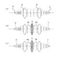
図3に透過型電磁波吸収材の電磁波透過特性及び吸収特性の評価方法を、図4に電磁波透過反射特性の評価方法をそれぞれ示す。
透過型電磁波吸収材の電磁波透過特性及び吸収特性の評価方法について説明すると、先ず、図3(a)のように、送信アンテナ6から発信させた電磁波を、レンズ8を通過させて受信アンテナ7で受信させる。このときの受信レベルを測定する。次に、アンテナ間に透過型電磁波吸収材9を挿入し、同じように受信レベルを測定する。尚、透過型電磁波吸収材9には、レンズを使用することによって、平面波が入射するようにする。
受信レベルは、図3(b)と図3(c)のように、双方向からの入射した時のレベルをそれぞれ測定するようにする。このとき、9a側からの入射の時の値を[A]、9b側からの入射の時の値を[B]とする。
透過率は、次の式によって計算する。
透過率(%)=(吸収材があるときの受信レベル÷吸収材が無いときの受信レベル)×100
吸収材をアンテナ間に挿入することによって、受信レベルが小さくなる。つまり、透過量を小さくすることができる。このとき、小さくなった分のエネルギーは、吸収材によって送信アンテナ6側に反射した成分と、吸収材の内部で熱エネルギーに変換された成分に分けることができる。
次に、反射量の測定方法を図4に示す。図4(a)に示すように、送信アンテナ6から発信させた電磁波は、完全反射板10によって再びアンテナ6に戻る。このときの受信レベルを測定する。次に、完全反射板10を取り去って、吸収材9を挿入する。このときの受信レベルを9a面、9b面のそれぞれで測定する。尚、反射率は、次の式で表すことができる。
反射率(%)=(吸収材がある時の受信レベル/完全反射板の時の受信レベル)×100
前述のように、反射量が大きいと、送信された電磁波との干渉によって通信エラーの原因となることが多いため、この反射量が小さいほうが透過型の電磁波吸収材として良いものであるということができる。
FIG. 3 shows a method for evaluating electromagnetic wave transmission characteristics and absorption characteristics of a transmission type electromagnetic wave absorbing material, and FIG. 4 shows a method for evaluating electromagnetic wave transmission / reflection characteristics.
The electromagnetic wave transmission characteristic and the evaluation method of the absorption characteristic of the transmission type electromagnetic wave absorbing material will be described. First, as shown in FIG. 3A, the electromagnetic wave transmitted from the
As for the reception level, as shown in FIGS. 3B and 3C, the levels when incident from both directions are measured. At this time, the value at the time of incidence from the 9a side is [A], and the value at the time of incidence from the 9b side is [B].
The transmittance is calculated by the following formula.
Transmittance (%) = (Reception level when there is an absorber / Reception level when there is no absorber) × 100
By inserting the absorber between the antennas, the reception level is reduced. That is, the transmission amount can be reduced. At this time, the reduced energy can be divided into a component reflected to the transmitting
Next, a method for measuring the amount of reflection is shown in FIG. As shown in FIG. 4A, the electromagnetic wave transmitted from the
Reflectivity (%) = (Reception level when there is an absorber / Reception level when using a perfect reflector) × 100
As described above, since a large amount of reflection often causes a communication error due to interference with transmitted electromagnetic waves, a smaller amount of reflection is better for a transmissive electromagnetic wave absorber. it can.
表1に実施例1、2及び比較例1の3GHz帯での透過率、吸収率及び反射率を示す。実施例1よりも、グラファイトの付着密度の大きい実施例2の方が、透過率が小さいことが分かる。また、双方向からの入射に対しても、実施例1及び2とも同じ特性を示すことが分かる。このように、グラファイトの付着密度を変えることで、透過量の調整が可能である。
尚、比較例1のように、グラファイトの付着量が大きい場合は、透過量が小さく、アンテナの送受信のレベル調整用としては使用できないことが分かる。
Table 1 shows the transmittance, absorptivity, and reflectance in the 3 GHz band of Examples 1 and 2 and Comparative Example 1. It turns out that the transmittance | permeability of Example 2 with larger adhesion density of a graphite is smaller than Example 1. FIG. Moreover, it turns out that Example 1 and 2 show the same characteristic also with respect to the incident from both directions. Thus, the amount of permeation can be adjusted by changing the adhesion density of graphite.
Note that, as in Comparative Example 1, when the adhesion amount of graphite is large, the transmission amount is small, and it can be seen that it cannot be used for adjusting the transmission / reception level of the antenna.

1 ガラス長繊維多孔質板
2 グラファイト付着ガラス長繊維多孔質板
3 グラファイト
4 ポリフッ化ビニール
5 透過型電磁波吸収材
6 送信アンテナ
7 送信アンテナ
9 透過型電磁波吸収材
10 完全反射板
DESCRIPTION OF
Claims (3)
Priority Applications (1)
| Application Number | Priority Date | Filing Date | Title |
|---|---|---|---|
| JP2004108448A JP2005294583A (en) | 2004-03-31 | 2004-03-31 | Transmissive radio wave absorbing member |
Applications Claiming Priority (1)
| Application Number | Priority Date | Filing Date | Title |
|---|---|---|---|
| JP2004108448A JP2005294583A (en) | 2004-03-31 | 2004-03-31 | Transmissive radio wave absorbing member |
Publications (1)
| Publication Number | Publication Date |
|---|---|
| JP2005294583A true JP2005294583A (en) | 2005-10-20 |
Family
ID=35327167
Family Applications (1)
| Application Number | Title | Priority Date | Filing Date |
|---|---|---|---|
| JP2004108448A Withdrawn JP2005294583A (en) | 2004-03-31 | 2004-03-31 | Transmissive radio wave absorbing member |
Country Status (1)
| Country | Link |
|---|---|
| JP (1) | JP2005294583A (en) |
Cited By (2)
| Publication number | Priority date | Publication date | Assignee | Title |
|---|---|---|---|---|
| JP2021175455A (en) * | 2020-05-01 | 2021-11-04 | 株式会社Soken | Biological information detection device |
| JP2021186397A (en) * | 2020-06-02 | 2021-12-13 | 株式会社Soken | Bio-information detection device |
-
2004
- 2004-03-31 JP JP2004108448A patent/JP2005294583A/en not_active Withdrawn
Cited By (4)
| Publication number | Priority date | Publication date | Assignee | Title |
|---|---|---|---|---|
| JP2021175455A (en) * | 2020-05-01 | 2021-11-04 | 株式会社Soken | Biological information detection device |
| JP7415776B2 (en) | 2020-05-01 | 2024-01-17 | 株式会社Soken | Biological information detection device |
| JP2021186397A (en) * | 2020-06-02 | 2021-12-13 | 株式会社Soken | Bio-information detection device |
| JP7468160B2 (en) | 2020-06-02 | 2024-04-16 | 株式会社Soken | Biometric information detection device |
Similar Documents
| Publication | Publication Date | Title |
|---|---|---|
| CN111916917B (en) | An MXene-based terahertz wave broadband superabsorbing foam | |
| US20080311373A1 (en) | Electromagnetic wave absorbing material and method for preparing the same | |
| JPS59176035A (en) | Fiber composite material | |
| JP2008135485A (en) | Radio wave absorber and manufacturing method thereof | |
| JP2004104063A (en) | Electromagnetic wave absorber | |
| CN108448247A (en) | A kind of high wave transparent type millimetre-wave radar antenna house | |
| US4480256A (en) | Microwave absorber | |
| JP2005294583A (en) | Transmissive radio wave absorbing member | |
| JP2000277973A (en) | Ferrite containing fiber and manufacture thereof | |
| CN217641795U (en) | Three-dimensional reconfigurable frequency selective wave absorber | |
| JP2004146801A (en) | Porous magnet, manufacturing method thereof, electric-wave absorber and magnet lens therewith | |
| JP4303388B2 (en) | Electromagnetic wave absorber and method for producing the same | |
| US20100200794A1 (en) | Method for producing an absorber for microwaves and absorber produced according to the method | |
| CN210441746U (en) | Wallboard of radar invisible shelter | |
| JP2016146374A (en) | Electromagnetic wave absorber | |
| WO2011016109A1 (en) | Wave absorber | |
| JP2009088107A (en) | Radio wave absorber, its accommodating method, and radio wave dark room | |
| CN101255292A (en) | High absorption lightweight electromagnetic wave absorbing coating | |
| JP4879077B2 (en) | Radio wave absorber | |
| JP4266204B2 (en) | Electromagnetic wave absorber and manufacturing method thereof | |
| TW529204B (en) | Electrowave absorbing panel | |
| CN108790334A (en) | A kind of suction wave layer and preparation method for intelligent automobile radar | |
| JP2005197307A (en) | Solid electromagnetic wave absorption material | |
| JPH0291997A (en) | Radiowave absorbing body | |
| JP4344288B2 (en) | Non-combustible sheet-like composition having electromagnetic wave absorption / sound absorption performance, electromagnetic wave absorption / sound absorption structure and sound insulation wall using the same |
Legal Events
| Date | Code | Title | Description |
|---|---|---|---|
| A621 | Written request for application examination |
Effective date: 20070330 Free format text: JAPANESE INTERMEDIATE CODE: A621 |
|
| A761 | Written withdrawal of application |
Free format text: JAPANESE INTERMEDIATE CODE: A761 Effective date: 20081028 |