JP2005294090A - Ion implantation device - Google Patents
Ion implantation device Download PDFInfo
- Publication number
- JP2005294090A JP2005294090A JP2004108744A JP2004108744A JP2005294090A JP 2005294090 A JP2005294090 A JP 2005294090A JP 2004108744 A JP2004108744 A JP 2004108744A JP 2004108744 A JP2004108744 A JP 2004108744A JP 2005294090 A JP2005294090 A JP 2005294090A
- Authority
- JP
- Japan
- Prior art keywords
- ion
- ion beam
- frequency
- substrate
- sheet
- Prior art date
- Legal status (The legal status is an assumption and is not a legal conclusion. Google has not performed a legal analysis and makes no representation as to the accuracy of the status listed.)
- Pending
Links
- 238000005468 ion implantation Methods 0.000 title claims abstract description 33
- 238000010884 ion-beam technique Methods 0.000 claims abstract description 133
- 239000000758 substrate Substances 0.000 claims abstract description 75
- 230000001133 acceleration Effects 0.000 claims description 61
- 238000000605 extraction Methods 0.000 claims description 18
- 230000032258 transport Effects 0.000 claims description 6
- 238000006386 neutralization reaction Methods 0.000 abstract description 5
- 238000004513 sizing Methods 0.000 abstract 2
- 230000005611 electricity Effects 0.000 abstract 1
- 230000003068 static effect Effects 0.000 abstract 1
- 150000002500 ions Chemical class 0.000 description 73
- 238000000926 separation method Methods 0.000 description 16
- 230000005684 electric field Effects 0.000 description 7
- 239000002245 particle Substances 0.000 description 6
- 230000007423 decrease Effects 0.000 description 5
- 238000009826 distribution Methods 0.000 description 4
- 230000001629 suppression Effects 0.000 description 4
- 230000001360 synchronised effect Effects 0.000 description 4
- 230000000694 effects Effects 0.000 description 3
- 239000012212 insulator Substances 0.000 description 3
- 230000007935 neutral effect Effects 0.000 description 3
- 230000015572 biosynthetic process Effects 0.000 description 2
- 229910052796 boron Inorganic materials 0.000 description 2
- 239000004020 conductor Substances 0.000 description 2
- 239000011521 glass Substances 0.000 description 2
- 230000001678 irradiating effect Effects 0.000 description 2
- 239000002994 raw material Substances 0.000 description 2
- 239000004065 semiconductor Substances 0.000 description 2
- 238000011144 upstream manufacturing Methods 0.000 description 2
- ZOXJGFHDIHLPTG-UHFFFAOYSA-N Boron Chemical compound [B] ZOXJGFHDIHLPTG-UHFFFAOYSA-N 0.000 description 1
- OAICVXFJPJFONN-UHFFFAOYSA-N Phosphorus Chemical compound [P] OAICVXFJPJFONN-UHFFFAOYSA-N 0.000 description 1
- 239000000470 constituent Substances 0.000 description 1
- 238000011109 contamination Methods 0.000 description 1
- 238000005520 cutting process Methods 0.000 description 1
- 238000010586 diagram Methods 0.000 description 1
- 238000010891 electric arc Methods 0.000 description 1
- 239000000284 extract Substances 0.000 description 1
- 238000002513 implantation Methods 0.000 description 1
- 238000002347 injection Methods 0.000 description 1
- 239000007924 injection Substances 0.000 description 1
- 238000004519 manufacturing process Methods 0.000 description 1
- 229910052698 phosphorus Inorganic materials 0.000 description 1
- 239000011574 phosphorus Substances 0.000 description 1
- -1 phosphorus or boron Chemical class 0.000 description 1
- 239000000126 substance Substances 0.000 description 1
Images

Landscapes
- Electron Sources, Ion Sources (AREA)
Abstract
Description
この発明は、例えば半導体基板、フラットパネルディスプレイ用のガラス基板等の基板(換言すれば、加工体または被処理体。以下同様)にイオンビームを照射してイオン注入を行うイオン注入装置に関し、より具体的には、基板の大面積化(換言すれば、大型化。以下同様)にうまく対応することができるイオン注入装置に関する。なお、イオンドーピング装置と呼ばれるものも、ここで言うイオン注入装置に含まれる。 The present invention relates to an ion implantation apparatus that performs ion implantation by irradiating a substrate such as a semiconductor substrate or a glass substrate for a flat panel display (in other words, a workpiece or an object to be processed; Specifically, the present invention relates to an ion implantation apparatus that can cope with an increase in the area of a substrate (in other words, an increase in size, the same applies hereinafter). Note that what is called an ion doping apparatus is also included in the ion implantation apparatus referred to here.
基板に、幅が広くかつ平行化されたイオンビームを照射することのできるイオン注入装置の一例が特許文献1に記載されている。当該イオン注入装置は、フリーマン型、バーナス型等の比較的小型のイオン源から、一方向に発散する扇形のイオンビームを引き出し、当該イオンビームを、質量分離マグネットを兼ねるビーム平行化マグネットを通すことによって、所望のイオン種を選別(質量分離)すると共に、幅が広くかつ平行化されたイオンビームを形成して、当該イオンビームを基板に照射する構成をしている。 An example of an ion implantation apparatus that can irradiate a substrate with a wide and collimated ion beam is described in Patent Document 1. The ion implantation apparatus extracts a fan-shaped ion beam that diverges in one direction from a relatively small ion source such as a Freeman type or a Bernas type, and passes the ion beam through a beam collimating magnet that also serves as a mass separation magnet. Thus, a desired ion species is selected (mass separated), a wide and parallel ion beam is formed, and the substrate is irradiated with the ion beam.
上記イオン注入装置は、基板の大面積化(例えば、1m程度以上の幅を有する基板)に対応するためには、ビーム平行化マグネットを大型化しなければならないので、その重量が非常に大きくなる。 In order to cope with an increase in the area of the substrate (for example, a substrate having a width of about 1 m or more), the ion implantation apparatus has to increase the size of the beam collimating magnet, and therefore its weight becomes very large.
また、イオンビームの広がる距離を長くして幅の広いイオンビームを得るためには、イオン源とビーム平行化マグネット間の距離を大きくしなければならない。 In addition, in order to obtain a wide ion beam by extending the ion beam spread distance, the distance between the ion source and the beam collimating magnet must be increased.
しかも、必要な質量分離性能を確保するためには、ビーム平行化マグネットと基板間の距離も大きくしなければならない。これは、所望のイオン種のイオンビームも不所望のイオン種のイオンビームもどちらも幅が広がっており、幅の広がったイオンビーム同士を互いに同一面内で分離するためには、大きい距離が必要だからである。 Moreover, in order to ensure the necessary mass separation performance, the distance between the beam collimating magnet and the substrate must also be increased. This is because both the ion beam of the desired ion species and the ion beam of the undesired ion species are widened, and a large distance is required to separate the widened ion beams from each other in the same plane. Because it is necessary.
以上の結果、基板の大面積化に対応するためには、イオン注入装置全体が大型化かつ大重量化すると共に、イオンビームの輸送距離が長くなってイオンビームと残留ガス分子との衝突確率が高くなり、イオンビームの中性化による損失が増大して注入効率が低下する。 As a result, in order to cope with an increase in the area of the substrate, the entire ion implantation apparatus becomes larger and heavier, and the ion beam transport distance becomes longer and the collision probability between the ion beam and residual gas molecules increases. The loss increases due to the neutralization of the ion beam, and the implantation efficiency decreases.
また、イオン源から引き出したイオンビームの発散を利用してイオンビームの幅を広げる上記従来技術では、イオンビームの幅を広げる程そのビーム電流密度が低下するので、基板の大面積化に対応しようとすると、1枚の基板当たりの処理速度が低下する。 Further, in the above-described prior art that expands the width of the ion beam by utilizing the divergence of the ion beam drawn from the ion source, the beam current density decreases as the width of the ion beam is expanded, so that it is necessary to cope with an increase in the area of the substrate. As a result, the processing speed per substrate decreases.
そこでこの発明は、装置全体の大型化、大重量化、イオンビームの中性化による損失発生および処理速度低下を抑制しつつ、基板の大面積化に対応することができるイオン注入装置を提供することを主たる目的としている。 Therefore, the present invention provides an ion implantation apparatus that can cope with an increase in the area of a substrate while suppressing loss generation and a reduction in processing speed due to an increase in the size and weight of the entire apparatus and neutralization of an ion beam. This is the main purpose.
この発明に係るイオン注入装置は、イオン源で発生させた、基板の幅よりも幅の広いシート状のイオンビームを、当該幅の関係を保った状態で基板に輸送して基板に照射する装置であって、基板に注入すべき所望のイオン種を含む前記シート状のイオンビームを発生するイオン源と、このイオン源から供給される前記イオンビームを通す筒状の電極であってその入口および出口に前記イオンビームが通るスリットをそれぞれ有する複数の高周波電極を直列に配置して成り、前記イオンビーム中の前記所望のイオン種を選別して多重加速してシート状のイオンビームを導出する高周波加速部と、この高周波加速部の各高周波電極に高周波電圧を印加して、当該高周波加速部と協働して前記所望のイオン種を選別すると共に多重加速を行う高周波電源と、前記高周波加速部から導出されたイオンビームをそのシート面に直交する側に偏向させて、前記所望のイオン種であってしかも所望のエネルギーを有するものを選別してシート状のイオンビームを導出する静電偏向器と、基板を保持するホルダを有していて、前記静電偏向器から導出されたシート状のイオンビームの照射領域内で、ホルダ上の基板を、当該イオンビームのシート面に実質的に直交する方向に往復駆動する基板駆動装置とを備えることを特徴としている。 The ion implantation apparatus according to the present invention transports a sheet-like ion beam generated by an ion source, which is wider than the width of the substrate, to the substrate while maintaining the relationship of the width, and irradiates the substrate. An ion source for generating the sheet-like ion beam containing a desired ion species to be implanted into the substrate, and a cylindrical electrode through which the ion beam supplied from the ion source passes and A plurality of high-frequency electrodes each having a slit through which the ion beam passes at the outlet are arranged in series, and the desired ion species in the ion beam are selected and subjected to multiple acceleration to derive a sheet-like ion beam. A high frequency that applies a high frequency voltage to the acceleration unit and each high frequency electrode of the high frequency acceleration unit to select the desired ion species and perform multiple acceleration in cooperation with the high frequency acceleration unit The ion beam derived from the source and the high-frequency accelerating unit is deflected to the side perpendicular to the sheet surface, and the desired ion species having the desired energy is selected to obtain a sheet-like ion beam. And a holder for holding the substrate, and within the irradiation region of the sheet-like ion beam derived from the electrostatic deflector, the substrate on the holder is And a substrate driving device that reciprocates in a direction substantially perpendicular to the sheet surface.
このイオン注入装置によれば、イオン源で発生させた、基板の幅よりも幅の広いシート状のイオンビームを、当該幅の関係を保った状態で輸送して、高周波加速部において所望のイオン種を選択的に多重加速して質量分離および多重加速を行い、かつ静電偏向器において所望のエネルギーを有するイオン種を選別してエネルギー分離を行って、ホルダ上の基板に照射してイオン注入を行うことができる。そして、上記幅の関係を有するシート状のイオンビームと、基板駆動装置による基板の上記往復駆動との協働によって、基板の全面にイオン注入を行うことができる。 According to this ion implantation apparatus, a sheet-like ion beam, which is generated by an ion source and wider than the width of the substrate, is transported in a state where the width relationship is maintained, and desired ions are generated in the high-frequency acceleration unit. Selective multiple acceleration to perform mass separation and multiple acceleration, select ion species with desired energy in an electrostatic deflector, perform energy separation, and irradiate the substrate on the holder for ion implantation It can be performed. Then, ion implantation can be performed on the entire surface of the substrate by the cooperation of the sheet-like ion beam having the above width relationship and the reciprocating driving of the substrate by the substrate driving device.
前記イオン源を、前記シート状のイオンビームの元になるプラズマを生成するのに用いるフィラメントであって、前記シート状のイオンビームの幅方向に配列された複数のフィラメントを有するものとし、かつこの発明に係るイオン注入装置は、前記イオン源の各フィラメントに流すフィラメント電流を互いに独立して制御することができる1以上のフィラメント電源を備えていても良い。 The ion source is a filament used to generate plasma that is the basis of the sheet-like ion beam, and has a plurality of filaments arranged in the width direction of the sheet-like ion beam, and this The ion implantation apparatus according to the invention may include one or more filament power sources that can independently control the filament currents flowing through the filaments of the ion source.
前記静電偏向器と前記ホルダとの間に、前記所望のエネルギーを有するシート状のイオンビームを選別して通過させる分析スリット板を設けておいても良い。 An analysis slit plate for selecting and passing the sheet-like ion beam having the desired energy may be provided between the electrostatic deflector and the holder.
前記高周波加速部を構成する各高周波電極は、その入口および出口のスリットの寸法よりも内部の断面寸法が大きいものとしても良い。 Each high-frequency electrode constituting the high-frequency accelerating portion may have an internal cross-sectional dimension larger than the dimension of the entrance and exit slits.
前記イオン源から引き出す前記イオンビームのエネルギーを決める直流の引出し電源から出力する引出し電圧を、前記高周波電源から前記高周波加速部の第1段目の高周波電極に印加する高周波電圧の波高値よりも小さく設定しておいても良い。 The extraction voltage output from the DC extraction power source that determines the energy of the ion beam extracted from the ion source is smaller than the peak value of the high-frequency voltage applied from the high-frequency power source to the first-stage high-frequency electrode of the high-frequency acceleration unit. You may set it.
請求項1に記載の発明によれば、イオン源で発生させた、基板の幅よりも幅の広いシート状のイオンビームを、当該幅の関係を保った状態で、高周波加速部において質量分離および多重加速することができるので、質量分離マグネットおよびビーム平行化マグネットが不要になる。その結果、これらのマグネットを用いる場合に比べて、装置全体の大型化および大重量化を大幅に抑制しつつ、基板の大面積化に対応することができる。 According to the first aspect of the present invention, the sheet-like ion beam generated by the ion source and having a width wider than the width of the substrate is subjected to mass separation and separation in the high-frequency acceleration section while maintaining the relationship of the width. Multiple accelerations are possible, eliminating the need for a mass separation magnet and a beam collimating magnet. As a result, compared with the case of using these magnets, it is possible to cope with an increase in the area of the substrate while greatly suppressing an increase in size and weight of the entire apparatus.
しかも、上記両マグネットが不要になると共に、前記従来技術のようにイオンビームの幅を広くしたり質量分離性能を確保するためにビーム輸送距離を大きくする必要がないので、イオン源から基板までのビーム輸送距離を短くすることができ、それによってイオンビームの中性化による損失発生を抑制することができる。 In addition, both the magnets are not necessary, and it is not necessary to increase the beam transport distance in order to increase the width of the ion beam or to secure the mass separation performance as in the prior art. The beam transport distance can be shortened, thereby suppressing the occurrence of loss due to neutralization of the ion beam.
また、イオン源から前記幅の関係を有するシート状のイオンビームを発生させ、当該幅の関係を保った状態で基板に輸送するので、前記従来技術のようにイオンビームの発散を利用して幅を広げることに起因するビーム電流密度低下は生じない。即ち、基板の大面積化に対しては、基板の幅に応じた幅のシート状のイオンビームを発生させて輸送することで容易に対応することができ、それによってビーム電流密度低下を防止することができるので、1枚の基板当たりの処理速度を低下させずに、基板の大面積化に対応することができる。 In addition, since a sheet-like ion beam having the width relationship is generated from the ion source and transported to the substrate while maintaining the width relationship, the ion beam divergence is utilized as in the prior art. There is no reduction in beam current density due to widening. That is, it is possible to easily cope with the increase in area of the substrate by generating and transporting a sheet-like ion beam having a width corresponding to the width of the substrate, thereby preventing a decrease in beam current density. Therefore, it is possible to cope with an increase in the area of the substrate without reducing the processing speed per substrate.
更に、前記静電偏向器においてエネルギー分離を行って、中性粒子や不所望エネルギーのイオン種を除去することができるので、これらが基板に入射して不所望なイオン注入が発生するのを防止することができる。 Furthermore, energy separation can be performed in the electrostatic deflector to remove neutral particles and undesired energy ion species, thereby preventing these ions from entering the substrate and causing unwanted ion implantation. can do.
請求項2に記載の発明によれば、イオン源は前記のような複数のフィラメントを有しており、かつ当該各フィラメントに流すフィラメント電流を互いに独立して制御することができるので、幅方向におけるビーム電流密度分布の均一性の良いシート状のイオンビームを発生させることが容易になる、という更なる効果を奏する。 According to the second aspect of the present invention, the ion source has a plurality of filaments as described above, and the filament currents flowing through the filaments can be controlled independently from each other. There is a further effect that it becomes easy to generate a sheet-like ion beam having a good uniformity of the beam current density distribution.
請求項3に記載の発明によれば、静電偏向器と分析スリット板とが協働して、エネルギー分離性能をより高めることができる、という更なる効果を奏する。 According to the invention described in claim 3, the electrostatic deflector and the analysis slit plate cooperate with each other, and there is a further effect that the energy separation performance can be further improved.
請求項4に記載の発明によれば、各高周波電極の内壁にイオンビームが衝突しにくくなるので、イオンビームの衝突によって各高周波電極の内壁に絶縁物層が形成されるのを抑制することができ、それによって、当該内壁の絶縁物層の帯電によってイオンビームの軌道が乱されるのを抑制することができる、という更なる効果を奏する。 According to the fourth aspect of the present invention, the ion beam does not easily collide with the inner wall of each high-frequency electrode, so that it is possible to suppress the formation of an insulating layer on the inner wall of each high-frequency electrode due to the collision of the ion beam. Thus, there is a further effect that the trajectory of the ion beam can be suppressed from being disturbed by the charging of the insulator layer on the inner wall.
請求項5に記載の発明によれば、前記電圧の関係によって、高周波加速部に入射するイオンビームを、当該高周波加速部における加速位相に同期した集団(バンチ)に成形して、当該加速位相とは逆位相時にイオンビームが高周波加速部に入射して損失が発生するのを抑制することができるので、高周波加速部におけるイオンビームの加速効率を高めることができる、という更なる効果を奏する。 According to the fifth aspect of the present invention, the ion beam incident on the high frequency acceleration unit is formed into a group (bunch) synchronized with the acceleration phase in the high frequency acceleration unit according to the voltage relationship, and the acceleration phase Since the ion beam can be prevented from being incident on the high-frequency acceleration unit during the reverse phase and loss can be suppressed, the ion beam acceleration efficiency in the high-frequency acceleration unit can be further increased.
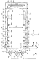
図1は、この発明に係るイオン注入装置の一実施形態を示す断面図である。図2は、図1の線A−Aに沿う断面図である。なお、引出し電極14のスリット14a、高周波電極36のスリット36a等の各スリットは、図1ではその存在を分かりやすくするために図示を簡略化して描いている。正確な図は図2に示している。
FIG. 1 is a sectional view showing an embodiment of an ion implantation apparatus according to the present invention. 2 is a cross-sectional view taken along line AA in FIG. The slits such as the
このイオン注入装置は、イオン源2で発生させた、基板66の幅WS よりも幅WB (いずれも図2または図4参照)の広いシート状のイオンビーム20を、当該幅の関係(即ちWB >WS の関係)を保った状態で、高周波加速部30および静電偏向器50等を通過させて、処理室容器64内のホルダ68に保持された基板66に輸送して基板66に照射して、当該基板66にイオン注入を行う構成をしている。
In this ion implantation apparatus, a sheet-
イオン源2内および当該イオン源2から処理室容器64内にかけてのイオンビーム20の経路(ビームライン)は、図示しない真空排気装置によって真空に排気される。例えば、高周波加速部30を収納している真空容器32および処理室容器64に真空排気装置をそれぞれ接続して、それらの内部およびそれにつながる部分を真空排気するようにしている。
The path (beam line) of the
イオン源2は、基板66に注入すべき所望のイオン種を含む前記シート状のイオンビーム20を発生する。「所望の」というのは、「所定の」または「特定の」と換言することができる(以下同様)。所望のイオン種は、イオンの質量と価数とによって特定することができる。
The
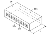
シート状のイオンビーム20は、図1では図示を簡略化するために、その厚さTB を極めて薄く描いているが、実際は、イオンビーム20の進行方向に垂直な断面形状は、図3、図4に示すように細長い長方形をしている。つまり、シート状のイオンビーム20は、その幅WB に比べて厚さTB が十分に小さい(例えば1/10〜1/100程度の)イオンビームのことであり、これは、帯状のイオンビームと換言することもできる。
The sheet-
イオン源2は、イオンビーム20の幅WB 方向に長く、1面が開いている長方形箱状のプラズマ生成容器4を有している。このプラズマ生成容器4内に、ガス導入口8を通して、前記所望のイオン種の原料となる物質を含む原料ガス10が導入される。
The
プラズマ生成容器4内には、イオンビーム20の幅WB 方向に、複数の熱陰極用のフィラメント6が配列されている。フィラメント6の数は、図2に示す3個に限られるものではなく、イオンビーム20の幅WB に応じて決めれば良い。例えば、当該幅WB が1m程度の場合、フィラメント6の数は10個程度にすれば良い。
The plasma generating chamber 4, the width W B direction of the
上記各フィラメント6に流すフィラメント電流を互いに独立して制御することができるフィラメント電源の一例として、この例では、各フィラメント6ごとに独立したフィラメント電源22を設けている。即ち、フィラメント6の数だけフィラメント電源22を設けている。但し、そのようにせずに、複数の電源を一つにまとめる等して、一つのフィラメント電源を用いて、各フィラメント6に流すフィラメント電流を互いに独立して制御することができるようにしても良い。
In this example, an independent
プラズマ生成容器4の開口部に引出し電極14を設け、その下流側(イオンビーム20の進行方向における進行方向側。以下同様)付近に抑制電極16を設け、更にその下流側付近に入口スリット板34を設けている。これら14、16、34は、イオンビーム20の断面形状に対応した形状をしていてシート状のイオンビーム20を通すスリット14a、16a、34aをそれぞれ有している。入口スリット板34は、高周波加速部30を構成するものであると言うこともできるし、イオン源2を構成する接地電極であると言うこともできる。両者を兼ねていると言うのが、より実情に合っている。引出し電極14と入口スリット板34との間には、筒状の絶縁物18が設けられている。入口スリット板は前記真空容器32と共に電気的に接地されている。
An
各フィラメント6の一端と引出し電極14との間には、前者を負極側にして、各フィラメント6とプラズマ生成容器4との間でアーク放電を生じさせて原料ガス10を電離させてプラズマ12を生成する直流のアーク電源24が接続されている。引出し電極14と接地電位部(ひいては当該接地電位部に接続された物。例えば入口スリット板34等。以下同様)との間には、前者を正極側にして、引出し電極14に引出し電圧VE を印加する直流の引出し電源26が接続されている。この引出し電源26から出力する引出し電圧VE によって、イオン源2から引き出すイオンビーム20のエネルギーが決まる。抑制電極16と接地電位部との間には、前者を負極側にして、直流の抑制電源28が接続されている。この抑制電極16は、下流側から電子が逆流するのを抑制する。
Between one end of each
上記のような構成によって、イオン源2から、より具体的にはそのプラズマ生成容器4内に生成されたプラズマ12から、基板66に注入すべき所望のイオン種を含む前記シート状のイオンビーム20が引き出される。
With the above-described configuration, the sheet-
このイオン源2は、前記のような複数のフィラメント6を有しており、かつ前記のように当該各フィラメント6に流すフィラメント電流を互いに独立して制御することができるので、幅WB 方向におけるビーム電流密度分布の均一性の良いシート状のイオンビーム20を発生させることが容易である。
The
イオンビーム20の幅WB 方向におけるビーム電流密度分布の均一性をより高めることは、基板66付近に到達するイオンビーム20の幅WB 方向におけるビーム電流密度分布をモニタして、そのモニタ情報に基づいて、各フィラメント6に流すフィラメント電流をフィードバック制御することによって達成することができる。例えば、ビーム電流密度が他よりも低い箇所がある場合、その箇所に対応するフィラメント6に流すフィラメント電流を増大させれば良い。逆の場合は逆にすれば良い。
To improve the uniformity of the beam current density distribution in the width W B direction of the
イオン源2の下流側には、当該イオン源2から供給されるイオンビーム20中の前記所望のイオン種を選別して(換言すれば選択的に。以下同様)多重加速してシート状のイオンビーム20を導出する高周波加速部30が設けられている。
On the downstream side of the
この高周波加速部30は、イオン源2から供給されるシート状のイオンビーム20を通す筒状の電極36を、複数個、互いに一直線上に直列に配置した構造をしている。これらは、前記真空容器32内に収納されている。各高周波電極36は、図3も参照して、長方形の断面形状を有する筒状のものであり、かつその入口および出口に、イオンビーム20の断面形状に対応した形状をしていてシート状のイオンビーム20を通すスリット36aをそれぞれ有している。
The high-
高周波電極36の数は、この実施形態では一例として5個であり、上流側から数えて奇数番目、即ち第1、第3および第5番目の高周波電極36は、電流導入端子40を介して高周波電源44の一端(非接地端)に接続され、偶数番目、即ち第2および第4番目の高周波電極36は、支持導体42および真空容器32を介して高周波電源44の他端(接地端)に接続されている。
In this embodiment, the number of the high-
高周波加速部30は、この実施形態では更に、第1番目の高周波電極36の上流側近傍および最終番目(この例では第5番目)の高周波電極36の下流側近傍に、入口スリット板34および出口スリット板38をそれぞれ有している。両スリット板34、38は、各高周波電極36のスリット36aと同様の形状をしていてシート状のイオンビーム20を通すスリット34aおよび38aをそれぞれ有している。両スリット板34、38は、電気的には、この例では真空容器32に接続されていて接地電位にある。
In this embodiment, the high-
上記のような接続関係によって、各高周波電極36に、更にこの例では各スリット板34、38にも、高周波電源44から、隣り合うもの同士間で位相が180度異なる高周波電圧が印加される。この高周波電源44は、高周波加速部30と協働して、所望のイオン種を選別すると共に多重加速を行う。
Due to the above connection relationship, a high-frequency voltage having a phase difference of 180 degrees between adjacent ones is applied from the high-
即ち、高周波電源44から上記のように印加される高周波電圧によって、入口スリット板34と第1段目の高周波電極36間、各高周波電極36間および出口スリット板38と最終段目の高周波電極36間の各ギャップ46に発生する高周波電界Eは、図1に例示するように、一つおきに方向が逆になる。高周波電圧の半周期後には、高周波電界Eは図示とは全て逆向きになる。
That is, by the high frequency voltage applied from the high
各高周波電極36のビーム進行方向における長さL(図3参照)を後段のものほど長くして、イオンビーム20中の所望のイオン種が、一つのギャップ46からその次のギャップ46まで飛行する時間が、前記高周波電圧の半周期またはその奇数倍に相当するように、各ギャップ46間の距離L1 〜L5 および高周波電圧の周波数を設定しているので、所望のイオン種のみが、高周波電圧の極性反転に同期して各ギャップ46で次々に加速される。即ち、加速が積み重ねられる。これを多重加速と言う。不所望なイオン種は、同期が取れないので多重加速されることなく、途中で押し戻されたり、軌道が逸れて高周波電極36に衝突する等して、高周波加速部30から殆ど導出されない。このような作用によって、高周波加速部30は、高周波電源44と協働して、イオンビーム20中から所望のイオン種を選別する(即ち質量分離する)と共に、当該所望のイオン種を多重加速して、所望のイオン種を主体とするシート状のイオンビーム20を導出することができる。
The length L (see FIG. 3) in the beam traveling direction of each high-
なお、各高周波電極36等への上記のような高周波電圧の印加を、この例のように一つの高周波電源44を用いて行う代わりに、複数の互いに同期の取れた高周波電源を用いて行っても良い。
It should be noted that the application of the high-frequency voltage as described above to each high-
高周波加速部30から導出されたイオンビーム20には、選択的に所望のエネルギーまで多重加速された所望のイオン種以外に、加速の途中で残留ガスとの衝突による電荷交換によって中性化した中性粒子や、加速の途中で同期状態から外れたために十分に加速されていない不所望エネルギーのイオンが少量混在している可能性がある。これらを除去するために、次のような静電偏向器50等を設けている。
The
即ち、上記真空容器32内であって高周波加速部30の下流側に、より具体的には出口スリット板38の下流側に、高周波加速部30から導出されたシート状のイオンビーム20が導入される静電偏向器50を設けている。この静電偏向器50は、所定の間隔をあけて相対向する一組の偏向電極52、54を有している。両偏向電極52、54の相対向面は、円弧状をしており、それぞれ一定の曲率半径を有している。より具体的には、両偏向電極52、54は、この例ではそれぞれ、円筒を所定の角度だけ切り取った形状をしている。この内外の偏向電極52、54には、電流導入端子56、支持導体58をそれぞれ介して、前者を負極側にして、直流の偏向電源60が接続されている。
That is, the sheet-
静電偏向器50は、上記構成によって、入射したイオンビーム20に、そのシート面(シート状のイオンビーム20の主面)20a(図2参照)に直交する方向の電界であって、幅WB 方向全体に均一な電界を加えて、イオンビーム20をそのシート面20aに直交する側に静電偏向させる。これによって、前記所望のイオン種であってしかも所望のエネルギーを有するものを選別して(即ちエネルギー分離して)、所望のエネルギーに加速された所望のイオン種から成るシート状のイオンビーム20を導出することができる。静電偏向器50内で、中性粒子は直進し、低速のイオンは大きな偏向角で偏向を受けるので、所望エネルギーのイオンビームから分離され除去される。
The
静電偏向器50と基板保持用のホルダ68との間に、この実施形態のように、静電偏向器50から導出された所望のエネルギーを有するシート状のイオンビーム20のみを選別して通過させる分析スリット板62を設けておくのが好ましい。この分析スリット板62は、イオンビーム20の断面形状に対応した形状をしていてシート状のイオンビーム20を通すスリット62aを有している。このような分析スリット板62を設けておくと、それと静電偏向器50とが協働して、エネルギー分離性能をより高めることができる。
As in this embodiment, only the sheet-
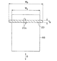
分析スリット板62を通過した上記シート状のイオンビーム20は、処理室容器64内に導入される。処理室容器64内には、基板66を保持するホルダ68が設けられており、このホルダ68およびその上の基板66は、上記イオンビーム20の照射領域内で、駆動装置72によって、連結部材70を介して、イオンビーム20のシート面20aに実質的に直交する方向Bに往復駆動(並進)させられる。図4も参照。これによって、基板66の全面に、所望のイオン種かつ所望のエネルギーのイオンビーム20を照射してイオン注入を行うことができる。
The sheet-
この実施形態では、上記ホルダ68、連結部材70および駆動装置72によって、ホルダ68上の基板66を上記のように往復駆動する基板駆動装置を構成しているけれども、基板駆動装置の構成はこのようなものに限られるものではない。例えば、駆動装置72は、図示例のように処理室容器64外に設けても良いし、処理室容器64内に設けても良い。
In this embodiment, the
基板66は、例えば、前述したように半導体基板、フラットパネルディスプレイ用のガラス基板等である。この基板66の平面形状は、例えば図4に示すように矩形であるが、それに限らない。この基板66の幅WS というのは、シート状のイオンビーム20の幅WB に対応する方向の寸法を言う。例えば、図4に示す例のように基板66が矩形の場合は、通常は、その短辺の長さを幅WS として扱う。
As described above, the
以上のように、このイオン注入装置によれば、イオン源2で発生させた、基板66の幅WS よりも幅WB の広いシート状のイオンビーム20を、当該幅の関係(即ちWB >WS )を保った状態で、高周波加速部30において質量分離および多重加速することができるので、質量分離マグネットおよびビーム平行化マグネットが不要になる。その結果、これらのマグネットを用いる場合に比べて、装置全体の大型化および大重量化を大幅に抑制しつつ、基板66の大面積化に対応することができる。
As described above, according to this ion implantation apparatus, the sheet-
しかも、上記両マグネットが不要になると共に、前記従来技術のようにイオンビームの幅を広くしたり質量分離性能を確保するためにビーム輸送距離を大きくする必要がないので、イオン源2から基板66までのビーム輸送距離を短くすることができ、それによってイオンビーム20の中性化による損失発生を抑制することができる。
In addition, both the magnets are not required, and it is not necessary to increase the beam transport distance in order to increase the width of the ion beam or ensure the mass separation performance as in the prior art. Can be shortened, and thereby the generation of loss due to neutralization of the
また、イオン源2から前記幅の関係を有するシート状のイオンビーム20を発生させ、当該幅の関係を保った状態で基板66に輸送するので、前記従来技術のようにイオンビームの発散を利用して幅を広げることに起因するビーム電流密度低下は生じない。即ち、基板66の大面積化に対しては、基板66の幅WS に応じた幅WS のシート状のイオンビーム20を発生させて輸送することで容易に対応することができる。具体的には、基板66の幅WS の増大に対応させて、イオン源2、高周波加速部30、静電偏向器50等の幅(上記幅WS に対応する方向の寸法)を大きくすることで、容易に対応することができる。それによって、イオンビーム20のビーム電流密度低下を防止することができるので、1枚の基板当たりの処理速度を低下させずに、基板66の大面積化に対応することができる。
Further, since the sheet-
更に、前記静電偏向器50においてエネルギー分離を行って、中性粒子や不所望エネルギーのイオン種を除去することができるので、これらが基板66に入射して不所望なイオン注入(例えば、中性粒子の入射による注入量誤差の発生や、不所望エネルギーイオンの入射によるエネルギーコンタミネーション等)が発生するのを防止することができる。
Furthermore, energy separation can be performed in the
また、高周波加速部30におけるイオンビーム20の加速には、静電加速器の場合と違って、比較的低い電圧(例えば10〜30kV程度)の高周波電圧を用いれば良いので、下流側からの逆流電子が各電極等に衝突することによって生じる制動X線の発生が殆どないため、静電加速器を用いたイオン注入装置では必要であった鉛シールドが不要になる。その結果、この理由によっても、装置全体の大幅な軽量化を図ることが可能になる。
Further, unlike the case of the electrostatic accelerator, a high frequency voltage of a relatively low voltage (for example, about 10 to 30 kV) may be used for accelerating the
なお、上記高周波加速部30を構成する各高周波電極36は、内部が入口および出口のスリット36aと同じ寸法の細長い角筒状のものでも良いけれども、図1〜図3に示す例のように、入口および出口のスリット36aの寸法よりも内部の断面寸法が大きいものにする方が好ましい。換言すれば、入口および出口のスリット36aの部分よりも内部が広いものにするのが好ましい。そのようにすれば、各高周波電極36の内壁にイオンビーム20が衝突しにくくなるので、イオンビーム20の衝突によって各高周波電極36の内壁に絶縁物層が形成されるのを抑制することができ、それによって、当該内壁の絶縁物層の帯電によってイオンビーム20の軌道が乱されるのを抑制することができる。
In addition, although each
ところで、高周波加速部30の各高周波電極36間のギャップ46には、更にこの例のように入口スリット板34および出口スリット板38を設けている場合はそれらと隣り合う高周波電極36との間のギャップ46にも、前述したように、イオンビーム20を加速する加速位相(順位相)とその逆位相(減速位相)の高周波電界Eが、高周波電圧の半周期ごとに交互に発生する。加速位相時に高周波加速部30に入射されたイオンビーム20は加速されるけれども、減速位相時に入射されたイオンビーム20は加速することができず、イオンおよび高周波電力の損失となる。
By the way, when the entrance slit
そこで、入口スリット板34と第1段目の高周波電極36間の高周波電界E(あるいは、入口スリット板34を設けていない場合は第1段目と第2段目の高周波電極36間の高周波電界E)に着目して、引出し電源26から出力する引出し電圧VE を、高周波電源44から第1段目の高周波電極36に印加する高周波電圧の波高値よりも小さく設定しておくのが好ましい。前述したように、引出し電圧VE は、イオン源2から引き出されるイオンビーム20のエネルギーを決定するので、この引出し電圧VE を上記のように設定しておくと、加速位相時にはイオンビーム20を構成するイオンは高周波加速部30に入射することができるけれども、逆位相時には当該イオンは逆位相高周波電圧に打ち勝つだけのエネルギーを有していないので押し戻されて、高周波加速部30に入射することができなくなる。
Therefore, a high-frequency electric field E between the entrance slit
このような作用によって、高周波加速部30に入射するイオンビーム20を、加速位相に同期した集団(バンチ)に成形して、逆位相時にイオンビーム20が高周波加速部30に入射して前記損失が発生するのを抑制することができる。その結果、イオンビーム20の有効利用を図ると共に、高周波電源44から出力する高周波電力の有効利用を図ることができる。即ち、高周波加速部30におけるイオンビーム20の加速効率を高めることができる。
By such an action, the
なお、この実施形態の高周波加速部30は、基本的には、ヴィデレー型線形加速器と呼ばれる加速器に属するけれども、一般的なヴィデレー型線形加速器は、予め質量分離された特定質量の荷電粒子(例えばイオンビーム)を入射させて多重加速するものであり、しかも加速するイオンビームの断面形状はスポット状(小さい円形またはそれに近い形状)のものであるのに対して、上記高周波加速部30は、イオン源2から供給される質量分離されていないシート状のイオンビーム20を入射させて当該シート状のイオンビーム20の質量分離と多重加速とを同時に行うものであり、この点で両者は異なっている。
The high-
前記所望のイオン種が、例えばリンやホウ素等のいわゆる重イオンの場合には、高周波加速部30は、この実施形態のようにヴィデレー型に属するものが好ましいけれども、この発明はそのようなイオン種に限定されるものではなく、高周波加速部30として、ヴィデレー型以外のもの、例えばアルバレ型または進行波型と呼ばれる線形加速器に属するものであって、シート状のイオンビーム20を通して、当該イオンビーム中の所望のイオン種を選別して多重加速するものを用いても良い。
When the desired ion species is a so-called heavy ion such as phosphorus or boron, the high-
2 イオン源
6 フィラメント
20 イオンビーム
22 フィラメント電源
26 引出し電源
30 高周波加速部
36 高周波電極
36a スリット
50 静電偏向器
62 分析スリット板
66 基板
68 ホルダ
72 駆動装置
2
Claims (5)
基板に注入すべき所望のイオン種を含む前記シート状のイオンビームを発生するイオン源と、
このイオン源から供給される前記イオンビームを通す筒状の電極であってその入口および出口に前記イオンビームが通るスリットをそれぞれ有する複数の高周波電極を直列に配置して成り、前記イオンビーム中の前記所望のイオン種を選別して多重加速してシート状のイオンビームを導出する高周波加速部と、
この高周波加速部の各高周波電極に高周波電圧を印加して、当該高周波加速部と協働して前記所望のイオン種を選別すると共に多重加速を行う高周波電源と、
前記高周波加速部から導出されたイオンビームをそのシート面に直交する側に偏向させて、前記所望のイオン種であってしかも所望のエネルギーを有するものを選別してシート状のイオンビームを導出する静電偏向器と、
基板を保持するホルダを有していて、前記静電偏向器から導出されたシート状のイオンビームの照射領域内で、ホルダ上の基板を、当該イオンビームのシート面に実質的に直交する方向に往復駆動する基板駆動装置とを備えることを特徴とするイオン注入装置。 An ion implantation apparatus that generates a sheet-like ion beam having a width wider than the width of the substrate generated by an ion source, transports the substrate to the substrate while maintaining the relationship of the width, and irradiates the substrate.
An ion source for generating the sheet-like ion beam containing a desired ion species to be implanted into the substrate;
A cylindrical electrode through which the ion beam supplied from the ion source passes, and a plurality of high-frequency electrodes each having a slit through which the ion beam passes at the entrance and the exit are arranged in series, A high-frequency accelerating unit that selects the desired ion species and performs multiple acceleration to derive a sheet-like ion beam;
A high-frequency power source that applies a high-frequency voltage to each high-frequency electrode of the high-frequency acceleration unit, selects the desired ion species in cooperation with the high-frequency acceleration unit, and performs multiple acceleration;
The ion beam derived from the high-frequency accelerator is deflected to the side perpendicular to the sheet surface, and the desired ion species having the desired energy is selected to derive a sheet-shaped ion beam. An electrostatic deflector;
A direction of the substrate on the holder that is substantially orthogonal to the sheet surface of the ion beam in the irradiation region of the sheet-shaped ion beam led out from the electrostatic deflector, the holder holding the substrate And a substrate driving device that reciprocates.
かつこのイオン注入装置は、前記イオン源の各フィラメントに流すフィラメント電流を互いに独立して制御することができる1以上のフィラメント電源を備えている請求項1記載のイオン注入装置。 The ion source is a filament used to generate plasma that is the basis of the sheet-like ion beam, and has a plurality of filaments arranged in the width direction of the sheet-like ion beam,
2. The ion implantation apparatus according to claim 1, further comprising at least one filament power source capable of independently controlling a filament current flowing through each filament of the ion source.
Priority Applications (1)
| Application Number | Priority Date | Filing Date | Title |
|---|---|---|---|
| JP2004108744A JP2005294090A (en) | 2004-04-01 | 2004-04-01 | Ion implantation device |
Applications Claiming Priority (1)
| Application Number | Priority Date | Filing Date | Title |
|---|---|---|---|
| JP2004108744A JP2005294090A (en) | 2004-04-01 | 2004-04-01 | Ion implantation device |
Publications (1)
| Publication Number | Publication Date |
|---|---|
| JP2005294090A true JP2005294090A (en) | 2005-10-20 |
Family
ID=35326782
Family Applications (1)
| Application Number | Title | Priority Date | Filing Date |
|---|---|---|---|
| JP2004108744A Pending JP2005294090A (en) | 2004-04-01 | 2004-04-01 | Ion implantation device |
Country Status (1)
| Country | Link |
|---|---|
| JP (1) | JP2005294090A (en) |
Cited By (3)
| Publication number | Priority date | Publication date | Assignee | Title |
|---|---|---|---|---|
| JP2008112673A (en) * | 2006-10-31 | 2008-05-15 | Nissin Ion Equipment Co Ltd | Ion implanting device |
| WO2009110506A1 (en) * | 2008-03-07 | 2009-09-11 | 三井造船株式会社 | Ion source |
| JP2017139074A (en) * | 2016-02-02 | 2017-08-10 | 俊 保坂 | Micro accelerator, micro mass spectrometer, and ion implanter |
-
2004
- 2004-04-01 JP JP2004108744A patent/JP2005294090A/en active Pending
Cited By (3)
| Publication number | Priority date | Publication date | Assignee | Title |
|---|---|---|---|---|
| JP2008112673A (en) * | 2006-10-31 | 2008-05-15 | Nissin Ion Equipment Co Ltd | Ion implanting device |
| WO2009110506A1 (en) * | 2008-03-07 | 2009-09-11 | 三井造船株式会社 | Ion source |
| JP2017139074A (en) * | 2016-02-02 | 2017-08-10 | 俊 保坂 | Micro accelerator, micro mass spectrometer, and ion implanter |
Similar Documents
| Publication | Publication Date | Title |
|---|---|---|
| US6803590B2 (en) | Ion beam mass separation filter, mass separation method thereof and ion source using the same | |
| JP3680274B2 (en) | Ion beam charge neutralization apparatus and method | |
| JP2016031849A5 (en) | ||
| JP4416632B2 (en) | Gas cluster ion beam irradiation apparatus and gas cluster ionization method | |
| JP6453756B2 (en) | Ion beam processing equipment | |
| US20180286653A1 (en) | Electrodynamic Mass Analysis | |
| JP2024540934A (en) | Mismatched optics for angular control of extracted ion beams. | |
| EP1662541B1 (en) | Ion beam processing system with a beam space-charge compensation device | |
| TWI850336B (en) | Apparatus, system and method of processing an ion beam | |
| JP2005294090A (en) | Ion implantation device | |
| JPH09237700A (en) | High frequency accelerator-decelerator, and usage thereof | |
| CN114223049A (en) | Mass spectrometer and method | |
| US20050200320A1 (en) | Method and apparatus for accelerating charged particles | |
| JP5634992B2 (en) | Ion beam irradiation apparatus and ion beam divergence suppression method | |
| JP5105729B2 (en) | Processing method with gas cluster ion beam | |
| JP2003257356A (en) | Ion beam irradiation device | |
| JP2004055390A (en) | Ion source | |
| JP4013377B2 (en) | Mass separation type ion source | |
| US10842012B2 (en) | Methods and systems for plasma self-compression | |
| JPH06252096A (en) | Semiconductor processing equipment | |
| US12573579B2 (en) | Hybrid apparatus, system and techniques for mass analyzed ion beam | |
| JP4336780B2 (en) | Ion source | |
| JP2001126656A (en) | Ion implantation device | |
| RU1766201C (en) | Ion source | |
| TW202503812A (en) | Apparatus, system and method for processing ion beam |