JP2005293994A - Lighting fixture - Google Patents
Lighting fixture Download PDFInfo
- Publication number
- JP2005293994A JP2005293994A JP2004106385A JP2004106385A JP2005293994A JP 2005293994 A JP2005293994 A JP 2005293994A JP 2004106385 A JP2004106385 A JP 2004106385A JP 2004106385 A JP2004106385 A JP 2004106385A JP 2005293994 A JP2005293994 A JP 2005293994A
- Authority
- JP
- Japan
- Prior art keywords
- led
- wiring board
- leds
- reflector
- reflecting plate
- Prior art date
- Legal status (The legal status is an assumption and is not a legal conclusion. Google has not performed a legal analysis and makes no representation as to the accuracy of the status listed.)
- Pending
Links
Images
Landscapes
- Traffic Control Systems (AREA)
- Non-Portable Lighting Devices Or Systems Thereof (AREA)
Abstract
【課題】少ない数のLEDでもその点灯を遠くからでも明るく視認することができ、スポット照明、電飾、交通信号灯としての用途に適した照明灯具を提供する。また、放熱性を改善しLEDの耐久性、寿命を向上させる。
【解決手段】複数のLEDが取り付けられた配線基板と、複数の凹窪が形成され該凹窪の内底部に透孔を開設したアルミ板製の反射板とを具備し、該反射板の背後に前記配線基板を配置しLEDを該透孔を貫通させ該反射板の前面に突出させてなる。
【選択図】図3Provided is an illumination lamp that can be lit brightly even from a distance even with a small number of LEDs, and is suitable for use as a spot lighting, electric decoration, or traffic signal lamp. It also improves heat dissipation and improves the durability and life of the LED.
A wiring board to which a plurality of LEDs are attached, and a reflecting plate made of an aluminum plate in which a plurality of depressions are formed and through holes are formed in the inner bottom of the depressions, The wiring board is disposed on the LED, and the LED penetrates the through hole and protrudes from the front surface of the reflector.
[Selection] Figure 3
Description
この発明は交通信号灯等に使用されるLEDを光源とする照明灯具に関するものである。 The present invention relates to an illuminating lamp that uses an LED as a light source for use in traffic signal lights and the like.
下記特許文献1に示された交通信号灯は、基板に複数のLEDを取り付け、該LEDの上方および下方に設けた反射板によって該LEDの光を下方に反射させ、通行人や車輌運転者に表示を見易くするものであった。また、前面に各LEDの光軸毎に個々にカットされたレンズを設けて各LEDの光軸を屈曲させ配光状態を適当に設定した交通信号灯も従来からなされている。
ところで、上記従来のように、LEDの上方および下方に設けた反射板やレンズによってLED光の指向方向を設定する構成では、LEDの設定位置が僅かに違っても光軸が大きくずれるおそれがあるので、構成,組立を複雑にし、精度を要するものであった。このため製造コストが高くなるものであった。
また、従来では上記LEDの近くに設けた反射板が、LEDの放熱性を悪くし、LEDが過熱状態となり、LED本来の耐久性、長寿命が損なわれるおそれがあった。
By the way, in the configuration in which the directivity direction of the LED light is set by the reflectors and lenses provided above and below the LED as in the conventional case, the optical axis may be greatly shifted even if the setting position of the LED is slightly different. As a result, the configuration and assembly are complicated and require precision. For this reason, the manufacturing cost is high.
In addition, conventionally, a reflector provided near the LED deteriorates the heat dissipation of the LED, the LED is overheated, and the inherent durability and long life of the LED may be impaired.
この発明の照明灯具は上記課題を解決しようとするもので、複数のLEDが取り付けられた配線基板と、複数の凹窪が形成され該凹窪の内底部に透孔を開設したアルミ板製の反射板とを具備し、該反射板の背後に前記配線基板を配置しLEDを該透孔を貫通させ該反射板の前面に突出させてなることを特徴とする。 The illuminating lamp of the present invention is intended to solve the above-mentioned problem, and is made of an aluminum plate in which a plurality of LEDs are attached and a plurality of recesses are formed and a through hole is formed in the inner bottom of the recess. A reflector, and the wiring board is disposed behind the reflector, and the LED penetrates the through hole and protrudes to the front of the reflector.
少ない数のLEDでもその点灯を遠くからでも明るく視認することができ、スポット照明、電飾、交通信号灯としての用途に適した照明灯具を提供できる。また、放熱性が改善されLEDの耐久性が向上する。 Even with a small number of LEDs, the lighting can be viewed brightly even from a distance, and it is possible to provide an illumination lamp suitable for use as a spot lighting, electric decoration, or traffic signal lamp. Moreover, heat dissipation is improved and the durability of the LED is improved.
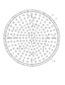
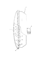
次にこの発明の実施例を図面に従い説明する。この照明灯具は、図1,図2に示したように、前面が開放された円形器状のケース1と、配線基板2と、アルミ板製の反射板3と、透明プラスチック製の前面カバー体4とからなる。5はケース1の後部に設けられた電源コネクタ、6はケース1と反射板3と前面カバー体4の周縁部を重合しその外側を包囲することにより、水分の侵入を防いでいるゴムパッキンである。
Next, embodiments of the present invention will be described with reference to the drawings. As shown in FIGS. 1 and 2, the lighting lamp includes a circular case 1 having an open front surface, a
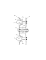
配線基板2には複数のLED7が適宜間隔を置いて取り付けられ、該各LED7に直流電源が供給されることにより点灯する。反射板3はアルミ板をプレス成形することにより内面が放射面状の凹窪8を適宜間隔で複数形成し、該各凹窪の内底部に透孔9を開設したものである。そして、図3にも示したように、該反射板の背後に配線基板2を配置し、LED7を該透孔9に貫通させ該反射板3の前面に突出させる。なお、LED7は略々砲弾形を呈しており、その底部に一体に成形された環状部7aが透孔9より大径であるようにし、該透孔9の内側縁に該環状部7aを当接させることで、該LED7の位置決めがなされる。これによって該LED7の発光部を該凹窪8の放射面の焦点に正確に位置させることができる。また、10は配線基板2と反射板3の間に介在するアルミ製の筒状スペーサ、11は該スペーサを貫通し反射板3の背後に配線基板2を固定しているボルト・ナットである。なお、反射板3はアルマイト加工して着色したものを使用することもできる。
A plurality of
このように構成した照明灯具では、点灯によりLED7から発せられた光が凹窪8の内面に反射され、前方に指向する。このため、少ない数のLEDでもその点灯を遠くからでも明るく視認することができ、交通信号灯としての用途に適する。また、指向性が高くできることからスポット照明、電飾、等の用途にも適する。
また、点灯中にLED7から発せられる熱は、熱伝導性の高いアルミ製であって全面に亘って設けられた広面積の反射板3を通して放熱され、さらに該反射板3の熱はアルミ製の筒状スペーサ10を介して配線基板2にも伝達されることから、LED7の過熱が防止され、その耐久性、寿命を向上させる。
In the illumination lamp configured in this way, the light emitted from the
Further, the heat generated from the
1 ケース
2 配線基板
3 反射板
4 前面カバー体
7 LED
8 凹窪
9 透孔
1
8 Recesses 9 Through holes
Claims (1)
Priority Applications (1)
| Application Number | Priority Date | Filing Date | Title |
|---|---|---|---|
| JP2004106385A JP2005293994A (en) | 2004-03-31 | 2004-03-31 | Lighting fixture |
Applications Claiming Priority (1)
| Application Number | Priority Date | Filing Date | Title |
|---|---|---|---|
| JP2004106385A JP2005293994A (en) | 2004-03-31 | 2004-03-31 | Lighting fixture |
Publications (1)
| Publication Number | Publication Date |
|---|---|
| JP2005293994A true JP2005293994A (en) | 2005-10-20 |
Family
ID=35326704
Family Applications (1)
| Application Number | Title | Priority Date | Filing Date |
|---|---|---|---|
| JP2004106385A Pending JP2005293994A (en) | 2004-03-31 | 2004-03-31 | Lighting fixture |
Country Status (1)
| Country | Link |
|---|---|
| JP (1) | JP2005293994A (en) |
Cited By (4)
| Publication number | Priority date | Publication date | Assignee | Title |
|---|---|---|---|---|
| JP2008159562A (en) * | 2006-11-30 | 2008-07-10 | Mirai Kankyo Kaihatsu Kenkyusho Kk | Lighting device |
| KR100919178B1 (en) * | 2009-03-09 | 2009-09-30 | 김남호 | Bar type led lighting device |
| WO2010125889A1 (en) * | 2009-04-27 | 2010-11-04 | 京セラ株式会社 | Light emitting device |
| WO2012063676A1 (en) * | 2010-11-08 | 2012-05-18 | シャープ株式会社 | Illumination device, display device and television receiverreception device |
-
2004
- 2004-03-31 JP JP2004106385A patent/JP2005293994A/en active Pending
Cited By (4)
| Publication number | Priority date | Publication date | Assignee | Title |
|---|---|---|---|---|
| JP2008159562A (en) * | 2006-11-30 | 2008-07-10 | Mirai Kankyo Kaihatsu Kenkyusho Kk | Lighting device |
| KR100919178B1 (en) * | 2009-03-09 | 2009-09-30 | 김남호 | Bar type led lighting device |
| WO2010125889A1 (en) * | 2009-04-27 | 2010-11-04 | 京セラ株式会社 | Light emitting device |
| WO2012063676A1 (en) * | 2010-11-08 | 2012-05-18 | シャープ株式会社 | Illumination device, display device and television receiverreception device |
Similar Documents
| Publication | Publication Date | Title |
|---|---|---|
| KR102410931B1 (en) | Retrofit lamp for automotive headlights | |
| JP4078002B2 (en) | Luminescent body and signal lamp | |
| US6637921B2 (en) | Replaceable LED bulb with interchangeable lens optic | |
| US8876331B2 (en) | Annular lighting fixture and method for illumination | |
| US7144144B2 (en) | Light release ring for vehicle lights | |
| JP2008053235A (en) | LED assembly for automobile rear lamp | |
| US20100195342A1 (en) | Automotive Signal Light Employing Multi-focal Length Light Pipes | |
| CN101457892A (en) | Vehicle lamp assembly | |
| JP2006294610A (en) | Virtual point light source | |
| JP5941383B2 (en) | Vehicle lighting | |
| CA2477649A1 (en) | Light emitting diode optics | |
| JP2011154912A (en) | Vehicular lighting fixture | |
| JP2005293994A (en) | Lighting fixture | |
| JP3145838U (en) | LED bulb | |
| EP2377721B1 (en) | Rear lamp for vehicles | |
| EP2184531A1 (en) | Warning lamp | |
| JP3574614B2 (en) | Light emitters and lamps | |
| JP7131186B2 (en) | Vehicle lighting device | |
| KR102012662B1 (en) | Tail lamp for vehicle with light guide film and flexible lighting | |
| CN219036411U (en) | Automobile working lamp capable of increasing irradiation range | |
| TWM604859U (en) | Car light and uniform light structure thereto | |
| JP7324090B2 (en) | Vehicle indicator light | |
| US11519580B1 (en) | Lighting device for vehicle | |
| JP2014038722A (en) | Vehicular lighting fixture | |
| KR102076543B1 (en) | Automotive headlamps with adjustable light distribution |
Legal Events
| Date | Code | Title | Description |
|---|---|---|---|
| A131 | Notification of reasons for refusal |
Free format text: JAPANESE INTERMEDIATE CODE: A131 Effective date: 20070320 |
|
| A02 | Decision of refusal |
Free format text: JAPANESE INTERMEDIATE CODE: A02 Effective date: 20070717 |