JP2005293898A - Conductor connecting pipe and connection method - Google Patents
Conductor connecting pipe and connection method Download PDFInfo
- Publication number
- JP2005293898A JP2005293898A JP2004103884A JP2004103884A JP2005293898A JP 2005293898 A JP2005293898 A JP 2005293898A JP 2004103884 A JP2004103884 A JP 2004103884A JP 2004103884 A JP2004103884 A JP 2004103884A JP 2005293898 A JP2005293898 A JP 2005293898A
- Authority
- JP
- Japan
- Prior art keywords
- main body
- cable
- conductor
- pressing means
- conductors
- Prior art date
- Legal status (The legal status is an assumption and is not a legal conclusion. Google has not performed a legal analysis and makes no representation as to the accuracy of the status listed.)
- Pending
Links
Images


Landscapes
- Connections By Means Of Piercing Elements, Nuts, Or Screws (AREA)
- Non-Insulated Conductors (AREA)
- Processing Of Terminals (AREA)
- Cable Accessories (AREA)
- Mutual Connection Of Rods And Tubes (AREA)
Abstract
Description
本発明は、電力ケーブルの導体を接続する導体接続管及びこれを用いた電力ケーブルの接続方法に関する。 The present invention relates to a conductor connecting tube for connecting a conductor of a power cable and a method for connecting a power cable using the conductor connecting tube.
従来、地中送電線として用いられているCVケーブルなどの電力ケーブルは、都市部等において道路下などに設けられた胴道や管路に布設されることが一般的である。これら地中に布設された電力ケーブル同士の接続部は、メンテナンスや工事空間確保の観点から、管路布設では道路地下などに形成されるマンホール内に設置される。 2. Description of the Related Art Conventionally, power cables such as CV cables used as underground power transmission lines are generally laid on trunk roads and pipelines provided below roads in urban areas and the like. The connection portion between the power cables laid in the ground is installed in a manhole formed in the underground of the road or the like in the pipe laying from the viewpoint of maintenance and construction space securing.
マンホールは、管路建設に比べ接続部設置ならびに接続作業用空間を確保するため、周囲を強固に囲ったホールになっており、マンホール自体の建設費が高く、マンホールの削減、内部空間の縮小化が図られている。また、マンホールは、道路地下などに利用されており、マンホール内での電力ケーブルの接続作業は、道路の交通に支障のないよう配慮され、通行量の少ない夜間など、限られた時間内で速やかに行う必要がある。このため、マンホール内で電力ケーブル同士を接続する際には、作業工程の効率化が要求される。 Compared with pipe construction, manholes are tightly enclosed holes to secure connection space and connection work space, manholes themselves are expensive to construct, reduce manholes, and reduce internal space Is planned. In addition, manholes are used in the underground of roads, and power cable connection work in the manholes is considered not to interfere with traffic on the roads. Need to be done. For this reason, when connecting power cables in a manhole, the efficiency of a work process is requested | required.
電力ケーブル同士の接続は、まず、導体を露出させた電力ケーブルの端部(以下、単に「ケーブル導体」という)同士を、導体接続管(導体接続スリーブ)を用いて接続する。次いで、この接続部分にはゴムテープなどを巻き上げたり、ゴム弾性体からなる常温収縮形絶縁ブロックを被せる等して被覆して、絶縁層を形成する。 To connect the power cables, first, the ends of the power cables with the conductors exposed (hereinafter simply referred to as “cable conductors”) are connected using a conductor connection tube (conductor connection sleeve). Next, the connecting portion is covered with a rubber tape or the like, or covered with a room temperature shrinkable insulating block made of a rubber elastic body to form an insulating layer.
従来のケーブル導体同士の接続には、例えば、特許文献1に示すように、導体接続管の両端の開口に、それぞれケーブル導体を挿入し、この導体接続管を、内部に挿入されたケーブル導体と共に油圧装置などにより外部から力を加えて押し潰し、両者を一体化する圧縮方式が用いられている。 For connection between conventional cable conductors, for example, as shown in Patent Document 1, cable conductors are inserted into openings at both ends of a conductor connection tube, and the conductor connection tube is connected to the cable conductor inserted inside. A compression method is used in which a force is applied from the outside by a hydraulic device or the like to crush and integrate them.
図13は、従来の導体接続管1を用いて電力ケーブル40、50の端部同士を接続した状態を示す断面図である。
FIG. 13 is a cross-sectional view showing a state in which the ends of the
図13に示す導体同士を接続する導体接続管1は、銅あるいはアルミニウム等の導電性の良い金属材料を筒状体に加工してなる。この筒状体からなる導体接続管1の両端の開口部2、3より、接続する電力ケーブルの導体4、5をそれぞれ挿入する。
The conductor connecting tube 1 for connecting the conductors shown in FIG. 13 is formed by processing a metal material having good conductivity such as copper or aluminum into a cylindrical body. The
そして、図示しない圧縮装置の丸形ダイス(図示せず)または六角ダイス(図示せず)内に、ケーブル導体4、5が挿入された導体接続管1を配置して、油圧で駆動するピストンにより、導体接続管1を、その外周側から軸心に向かって圧縮することにより潰す。これにより、導体接続管1は導体に圧着され、ケーブル導体4、5と強固に接触される。
Then, a conductor connecting pipe 1 into which the
このようにケーブル導体4、5に圧着された導体接続管1は、電力ケーブル40、50の引っ張り強度ならびにケーブル運転時に流される電流を確保し、さらに、ケーブル使用温度以上に発熱しないように電力ケーブル40、50同士を接続する。
Thus, the conductor connection tube 1 crimped to the
また、上記導体接続管1を用いたケーブル導体同士の接続では、圧縮方式の他に、ケーブル導体を形成している素線を溶かして接続する溶接方式が用いられている。
しかしながら、従来の導体接続管を用いた圧縮式の導体の接続方法では、重量が大きい圧縮装置を用いるため、マンホールの限られた空間内で、圧着装置の運搬、設置、操作等には、手間が掛かるという問題がある。また、導体接続管が大きいサイズである場合、全体を一度の圧縮で潰すためにはそのための装置も大型化、大重量化する必要があり、多くの労力と長時間を必要とするなど効率が悪くなる。 However, in the conventional method of connecting a compression type conductor using a conductor connection tube, since a heavy weight compression device is used, it is troublesome to transport, install and operate the crimping device in a limited space of a manhole. There is a problem that it takes. In addition, when the conductor connection pipe is large in size, it is necessary to increase the size and weight of the device for crushing the whole with a single compression, which requires a lot of labor and a long time. Deteriorate.
この場合、圧縮装置を大型化せず使用するには、導体接続管を数回に渡って圧縮する方法もあるが、数回圧縮する場合、同じ状態で圧縮することは難しく、圧縮される導体接続管は変形しやすく、絶縁層を被せて完成する接続部自体に曲がりが生じる。変形が大きすぎると接続性能への影響が懸念される。 In this case, there is a method of compressing the conductor connecting tube several times in order to use the compression device without increasing the size, but when compressing several times, it is difficult to compress in the same state, and the conductor to be compressed The connecting pipe is easily deformed, and the connecting portion itself that is completed by covering the insulating layer is bent. If the deformation is too large, the connection performance may be affected.
また、導体接続方式として、導体同士を溶接することで接続する溶接方式では、導体を溶かすため、高温を発生させる。それには火薬やアーク放電発生装置の使用など、大がかりな装置や危険が伴う。加えて、熟練を要し、装置の設営や作業準備に手間が掛かる等、施工時間の短縮には限界がある。 Moreover, in the welding system which connects as a conductor connection system by welding conductors, in order to melt a conductor, high temperature is generated. This involves major equipment and dangers such as the use of gunpowder and arc discharge generators. In addition, there is a limit to shortening the construction time because it requires skill and takes time to set up the apparatus and prepare the work.
本発明はかかる点に鑑みてなされたものであり、狭い作業空間でも、電力ケーブル導体同士を、ケーブルの引っ張り強度を確保しつつ確実に、且つ、熟練を要さず容易に接続できる導体接続管及びケーブル導体の接続方法を提供することを目的とする。 The present invention has been made in view of the above points, and is a conductor connection tube that can reliably connect power cable conductors to each other even in a narrow work space, while ensuring the tensile strength of the cable and without requiring skill. And it aims at providing the connection method of a cable conductor.
本発明の導体接続管は、電力ケーブルの、導体が露出するケーブル端部が挿入される本体部と、前記本体部内に挿入された前記ケーブル端部を、前記ケーブル端部の外周面の一部を押圧して、前記本体部の内面に当接させる押圧手段とを有する構成を採る。 The conductor connection pipe of the present invention includes a main body portion into which a cable end portion where a conductor is exposed of a power cable is inserted, and the cable end portion inserted into the main body portion into a part of an outer peripheral surface of the cable end portion. And a pressing means for pressing against the inner surface of the main body.
この構成によれば、本体部にケーブル端部を挿入して、押圧手段により、本体部内のケーブル端部を、ケーブル端部の外周面の一部を押圧して本体部の内面に当接させるため、ケーブル端部の外周面の一部を押圧するだけで、ケーブル端部を本体部の内面に面接触させて、容易に電気的に接続することができる。つまり、接続すべきケーブル端部同士の接続に用いることで、本導体接続管を介してケーブル端部同士を確実に且つ、容易に電気的に接続することができる。また、押圧手段は、ケーブル端部を、その外周面の一部を押圧して本体部の内面に当接させるため、電力ケーブルを本体部への挿入方向と反対の方向に引っ張る力(電力ケーブルを本体部から抜く力)、つまり、引っ張り強度にも耐えることができる。 According to this configuration, the cable end portion is inserted into the main body portion, and the cable end portion inside the main body portion is pressed against the inner surface of the main body portion by pressing a part of the outer peripheral surface of the cable end portion by the pressing means. Therefore, the cable end can be brought into surface contact with the inner surface of the main body and can be easily electrically connected by simply pressing a part of the outer peripheral surface of the cable end. That is, by using the connection between the cable ends to be connected, the cable ends can be reliably and easily electrically connected via the conductor connection pipe. In addition, the pressing means presses a part of the outer peripheral surface of the cable end portion so as to contact the inner surface of the main body portion. Therefore, the pressing means pulls the power cable in a direction opposite to the insertion direction into the main body portion (power cable). It is possible to withstand the tensile strength).
したがって、従来と異なり、圧縮方式及び溶接方式を用いることなく、狭い作業空間でも、電力ケーブルの端部で露出するケーブル導体同士の電気的接続による送電容量ならびに、ケーブルの引っ張り強度を確保しつつ確実に、且つ、熟練を要さず容易に接続できる。 Therefore, unlike the conventional case, without using a compression method and a welding method, even in a narrow work space, the power transmission capacity by the electrical connection between the cable conductors exposed at the ends of the power cable and the tensile strength of the cable are ensured. In addition, it can be easily connected without requiring skill.
なお、押圧手段としては、ボルト等が挙げられる。押圧手段がボルトである場合、ボルトを締めるだけで、その先端部でケーブル端部を押圧して、ケーブル端部において、ボルトによる外周面の一部と反対側の面を本体部の内面に当接させて容易に電気的に接続することができ、機械的強度を確保すると共に、押圧手段自体を容易に製造することができる。 In addition, a bolt etc. are mentioned as a press means. When the pressing means is a bolt, just tighten the bolt and press the cable end with its tip, and at the cable end, touch the surface on the opposite side of the outer peripheral surface with the bolt against the inner surface of the body. They can be easily connected to each other and electrically connected to ensure mechanical strength, and the pressing means itself can be easily manufactured.
本発明の導体接続管は、上記構成において、前記押圧手段は、複数設けられ、前記複数の押圧手段は、前記本体部の同一円周上に互いに対向しない位置に配置されている構成を採る。 The conductor connection pipe according to the present invention employs a configuration in which, in the above-described configuration, a plurality of the pressing means are provided, and the plurality of pressing means are arranged at positions that do not face each other on the same circumference of the main body.
この構成によれば、複数の押圧手段は、本体部の同一円周上に互いに対向しない位置に配置されているため、複数の押圧手段のそれぞれが、ケーブル端部を押圧した際に、押圧断面に力が集中することがなく、ケーブル端部に対する引っ張り強度の低下を防ぐことができる。 According to this configuration, since the plurality of pressing means are arranged at positions that do not oppose each other on the same circumference of the main body portion, when each of the plurality of pressing means presses the cable end, The force is not concentrated on the cable end, and the decrease in the tensile strength with respect to the cable end can be prevented.
本発明の導体接続管は、上記構成において、前記押圧手段は、複数設けられ、前記複数の押圧手段は、本体部に螺線状に取り付けられている構成を採る。 The conductor connection pipe of the present invention employs a configuration in which, in the above configuration, a plurality of the pressing means are provided, and the plurality of pressing means are attached to the main body in a spiral shape.
この構成によれば、複数の押圧手段は、筒状本体部に螺旋状に配置されているため、本体部の軸線と直交する同一平面で、押圧手段同士が対向することがない。このため、複数の押圧手段により外周面の一部がそれぞれ押圧されるケーブル端部を、本体部の内面に効率よく当接させて、広い接触面積で電気的に接続することができる。 According to this configuration, since the plurality of pressing means are spirally arranged on the cylindrical main body, the pressing means do not face each other on the same plane orthogonal to the axis of the main body. For this reason, the cable end part by which a part of outer peripheral surface is each pressed by the some press means can be efficiently contact | abutted to the inner surface of a main-body part, and can be electrically connected with a wide contact area.
本発明の導体接続管は、上記構成において、前記押圧手段の先端部には、前記ケーブル端部に食い込む食い込み部が形成されている構成を採る。 The conductor connection pipe of the present invention employs a configuration in which, in the above configuration, a biting portion that bites into the cable end portion is formed at the tip of the pressing means.
この構成によれば、押圧手段の先端部が、ケーブル端部を押圧した際、ケーブル端部に食い込むため、本体部に接続されたケーブル端部の引っ張り強度を向上させ、本体部から抜けにくくすることができる。 According to this configuration, when the distal end portion of the pressing means bites into the cable end portion when pressing the cable end portion, the tensile strength of the cable end portion connected to the main body portion is improved and it is difficult to come out from the main body portion. be able to.
本発明の導体接続管は、上記構成において、前記押圧手段は、前記食い込み部の周囲に、前記食い込み部よりも前記ケーブル端部に対する接触面積が広い面接触部を有する構成を採る。 The conductor connection pipe according to the present invention has a configuration in which, in the above configuration, the pressing means has a surface contact portion having a contact area larger than the biting portion with respect to the cable end portion around the biting portion.
この構成によれば、押圧手段は、食い込みの際に、ケーブル端部の外周面の一部を押圧する食い込み部とともに、この食い込み部よりも接触面積が広い面接触部を有するため、押圧手段によりケーブル端部を押圧した際に、面接触部がケーブル端部の外周面の一部に当接する。 According to this configuration, the pressing means has a biting portion that presses a part of the outer peripheral surface of the cable end portion when biting, and a surface contact portion having a wider contact area than the biting portion. When the cable end is pressed, the surface contact portion comes into contact with a part of the outer peripheral surface of the cable end.
よって、ケーブル端部の筒状本体部に対する接触面積を大きくすることでき、電流を流すための電気抵抗を低く抑えることができる。また、押圧手段を導電性を有する部材に形成した場合、この押圧手段を介してケーブル端部を本体部に電気的に接続させることができる。 Therefore, the contact area of the cable end with respect to the cylindrical main body can be increased, and the electrical resistance for flowing current can be kept low. Further, when the pressing means is formed on a conductive member, the cable end can be electrically connected to the main body through the pressing means.
本発明の電力ケーブルの接続方法は、請求項1記載の導体接続管を用いて、電力ケーブルの、導体が露出する端部を接続する接続方法であって、前記導体接続管の本体部に、前記電力ケーブルの端部を挿入し、次いで、前記本体部に挿入された前記ケーブル端部を押圧手段により押圧して、前記ケーブル端部を前記本体部の内面に当接させるようにした。 The connection method of the power cable of the present invention is a connection method of connecting the end portion of the power cable, where the conductor is exposed, using the conductor connection tube according to claim 1, The end portion of the power cable was inserted, and then the cable end portion inserted into the main body portion was pressed by pressing means so that the cable end portion was brought into contact with the inner surface of the main body portion.
この方法によれば、導体が露出するケーブル端部を本体部に挿入して、押圧手段により本体部内のケーブル端部を、その外周面の一部を押圧して、筒状本体部の内面に当接させるため、押圧手段により押圧するだけで、ケーブル端部を導体接続管に接続することができる。したがって、従来と異なり、圧縮方式及び溶接方式を用いることなく、狭い作業空間でも、電力ケーブルの端部で露出するケーブル導体同士を、ケーブルの引っ張り強度を確保しつつ確実に、且つ、熟練を要さず容易に接続できる。 According to this method, the cable end portion where the conductor is exposed is inserted into the main body portion, the cable end portion in the main body portion is pressed by the pressing means, and a part of the outer peripheral surface is pressed to the inner surface of the cylindrical main body portion. In order to make contact, the cable end can be connected to the conductor connecting tube simply by pressing with the pressing means. Therefore, unlike conventional methods, the cable conductors exposed at the ends of the power cable can be reliably and skillfully secured between the cable conductors exposed at the ends of the power cable even in a narrow work space without using a compression method and a welding method. Easy connection.
本発明の導体接続部は、電力ケーブルにおいて導体が露出するケーブル端部と、導電性を有し、前記ケーブル端部が挿入される本体部と、前記本体部に挿入された前記ケーブル端部を、前記ケーブル端部の外周面の一部を押圧して、前記本体部内面に当接させる押圧手段とを有する構成を採る。 The conductor connection portion of the present invention includes a cable end portion where a conductor is exposed in a power cable, a conductive main body portion into which the cable end portion is inserted, and the cable end portion inserted into the main body portion. And a pressing means that presses a part of the outer peripheral surface of the cable end portion and contacts the inner surface of the main body.
この構成によれば、本体部に挿入された電力ケーブルのケーブル端部が、その外周面の一部を押圧手段により押圧されることにより、本体部の内面に当接されているため、電力ケーブルの端部と導電性を有する本体部とを熟練を必要とすることなく容易に接続することができる。すなわち、従来と異なり、圧縮方式及び溶接方式を用いることなく、狭い作業空間でも、電力ケーブルの端部で露出するケーブル導体を、導体接続管に、ケーブルの引っ張り強度を確保しつつ確実に、且つ、熟練を要さず容易に接続できる。これにより、ケーブル端部同士を確実に且つ容易に、短時間で、接続することができる。 According to this configuration, the cable end of the power cable inserted into the main body is brought into contact with the inner surface of the main body by pressing a part of its outer peripheral surface with the pressing means. It is possible to easily connect the end portion of the metal and the conductive main body portion without requiring skill. That is, unlike the conventional case, the cable conductor exposed at the end of the power cable can be securely connected to the conductor connection pipe while ensuring the tensile strength of the cable without using the compression method and the welding method, Can be connected easily without requiring skill. Thereby, the cable end portions can be reliably and easily connected in a short time.
以上説明したように、本発明によれば、狭い作業空間でも、電力ケーブル導体同士を、ケーブルの引っ張り強度を確保しつつ確実に、且つ、熟練を要さず容易に、短時間で、接続することができる。 As described above, according to the present invention, even in a narrow work space, the power cable conductors can be reliably and easily connected in a short time while securing the tensile strength of the cable and without requiring skill. be able to.
以下、本発明の実施の形態について、図面を参照して詳細に説明する。 Hereinafter, embodiments of the present invention will be described in detail with reference to the drawings.
(実施の形態1)
図1は、本発明の実施の形態1に係る導体接続管を用いた電力ケーブルの接続部を示す部分断面図である。
(Embodiment 1)
FIG. 1 is a partial cross-sectional view showing a connecting portion of a power cable using a conductor connecting tube according to Embodiment 1 of the present invention.
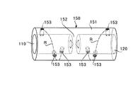
図1に示す電力ケーブルの接続部10は、一対の電力ケーブル40、50を導体接続管100を介して接続してなる。導体接続管100は、露出する一対の電力ケーブル40、50の導体4、5が開口部110、120を介して挿入される筒状の本体部150と、開口部110、120からそれぞれ挿入されたケーブル導体4、5を本体部150の内面(詳細には、本体部150の内周面の一部)113、123に押圧して電気的に接触させる押圧手段130とを有する。
The power
なお、互いに接続される一対の電力ケーブル40、50は、電気絶縁材料としてゴムプラスチック材料を用いたゴムプラスチック絶縁電力ケーブルである。
The pair of
これら電力ケーブル40,50は、それぞれ、端部を除くケーブル導体の周囲を内側から順に内部半導電層、ケーブル絶縁体および外部半導電層で被覆して構成されている。なお、この実施の形態のケーブル導体は、より線導体である。
Each of the
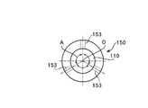
図2は、本発明の実施の形態1に係る導体接続管の本体部の斜視図、図3は、同本体部の側面図である。 FIG. 2 is a perspective view of the main body portion of the conductor connection pipe according to Embodiment 1 of the present invention, and FIG. 3 is a side view of the main body portion.
本体部150は、例えば、金属などの導電性を有する部材により形成され、両端に開口部110、120を有する。また、この本体部150には、内部中央に隔壁部152が設けられ、この隔壁部152を介して左右の内部空間にそれぞれケーブル導体4,5が挿入される。この本体部150の内径は、導体4、5が露出するケーブル端部(以下、「ケーブル導体」という)の外径と略同じ長さとなっている。
The
また、この本体部150には、押圧手段130が設けられる取付孔153が複数形成されている。
The
取付孔153は、本体部150の周壁部151の内部と外部とを連通するネジ取付孔である。取付孔153の軸線は本体部150の周壁部151から本体部150の軸線を通る位置に形成されている。
The
また、複数の取付孔153は、本体部150の同一円周上に配置されておらず、互いに、それぞれ対向しない位置に配置されている。ここでは、複数の取付孔153は、それぞれ周壁部151に仮想的に描く螺線R上に位置して形成されている。
The plurality of attachment holes 153 are not arranged on the same circumference of the
そして、これら取付孔153は、図3に示すように、本体部150の軸方向から見て、本体部150の円周上に等間隔に、言い換えれば、本体部150の軸心Oを中心に等角度Aの位置に形成されている。ここでは、取付孔153は、側面視して、互いに、軸心Oを中心に120°の角度を空けて配置されている。
As shown in FIG. 3, these mounting
なお、取付孔153の数、つまり押圧手段130が本体部150に取り付けられる数は、本体部150に接続されるケーブル導体4、5を引っ張る際に耐えうる強さに匹敵、あるいは、その強さに対して裕度を持たせた強さを有し、且つ、電気的接触抵抗が必要最小限度となる数とする。
Note that the number of attachment holes 153, that is, the number of
また、これら取付孔153の配置は、本体部150の電流容量を損なわないように、本体部150とケーブル導体4、5との接触面積を確保可能な配置とする。
Further, the mounting
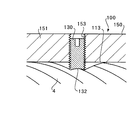
図4は、図1に示す導体接続管の押圧手段の一例を示す図である。 FIG. 4 is a view showing an example of the pressing means of the conductor connection pipe shown in FIG.
図4に示す押圧手段130は、導体接続管100の本体部150に形成された取付孔153に取り付けられ、本体部150の内面から突出し、本体部150内のケーブル導体4、5の外周面の一部を押圧する。また、押圧手段130は、その押圧状態を維持して、押圧する一部の外周面の一部と反対側の外周面の一部を押圧手段130の対向する内面に密着させる。
The pressing means 130 shown in FIG. 4 is attached to an
押圧手段130は、ここでは、外周面に雄ねじを形成した六角穴付きボルトが適切であり、その先端部には、ケーブル導体4、5の外周面に食い込む食い込み部132が形成されている。この食い込み部132の構成としては、例えば、押圧手段130としてのボルトの先端部をあら先や、窪み先にした構成が挙げられる。図4では、食い込み部を窪み先としている。雄ねじは六角穴付きボルトでなく、回転可能な機構を設けたネジであれば何でもよい。また、通常の六角頭付きボルトである場合には、六角頭部分が導体接続管100の外周面から飛び出さず、尚かつ、導体4、5に加えられる締め付け力が確保できるのに必要なボルトの締め代を持つよう導体接続管100に六角頭が入り回転できる溝を持たせる構造に加工してもよい。
Here, the pressing means 130 is suitably a hexagon socket head cap screw having a male screw formed on the outer peripheral surface, and a biting
先端部を窪み先(食い込み部132)とした押圧手段130としてのボルトが、ボルト孔である取付孔153にそれぞれねじ込まれている。このねじ込み具合により、先端部である食い込み部132は、本体部150の内周面から内方に向かってそれぞれ出没する。つまり、ねじ込み度合いにより、食い込み部132は、本体部150の内周面から内方に向かって突出する度合いを調整される。
Bolts as the pressing means 130 having the tip portion as a dent (bite portion 132) are respectively screwed into the mounting
この導体接続管100は、本体部150内に、開口部110、120のそれぞれから電力ケーブルの導体4、5を挿入し、ボルト130をねじ込むことにより先端部を本体部150の内周面から軸心に突出させる。
The
突出した先端部132は、先端部132と対向する導体4、5の外周面の一部を押圧する。このとき先端部132は外周面の一部に食い込みながらケーブル導体4(5)を押圧する。
The protruding
外周面の一部をそれぞれ押圧されたケーブル導体4、5では、外周面の一部と反対側の外周面が、取付孔153の位置に対向する内面113、123(詳細には、内面113、123において、取付孔153の軸線と同一軸線上に位置する部分)に押し付けられることでケーブル導体4、5と内面113、123が密着する。
In the
これによりケーブル導体4、5の一部に押圧を加える押圧手段130の反対側のケーブル導体外周面が対向する内面113、123と電気的に接触する。この対向面には取付孔153は配置されていないため、対向面側に押圧されたケーブル導体4,5は、内面113、123に面接触して、電流を流すための電気抵抗を低く抑え、通電による温度上昇を防ぐことができる。
As a result, the outer peripheral surface of the cable conductor opposite to the pressing means 130 that presses a part of the
なお、押圧手段130は、ボルトにより構成したが、これに限らず、ケーブル導体4、5を外周面の一部を押圧することで他の外周面の一部、ここでは、押圧する一部と反対側の外周面の一部を、本体部150の内面113、123に密着するものであれば、どのように構成されてもよい。
In addition, although the
本実施の形態によれば、押圧手段130により、本体部150内のケーブル導体4、5の外周面の一部を押圧するだけで、ケーブル導体4、5を本体部150の内面に面接触させて、確実に、且つ、容易に、電気的に接続することができる。つまり、接続すべきケーブル導体4、5同士の接続に用いることで、本導体接続管100を介してケーブル導体4、5同士を確実に且つ、容易に電気的に接続することができる。
According to the present embodiment, the
また、押圧手段130により、ケーブル導体4、5を本体部150に電気的に接続するため、電力ケーブル40、50のケーブル導体4、5を本体部150への挿入方向と反対の方向に引っ張る力(電力ケーブル40、50を本体部150から抜く力)、つまり、引っ張り強度にも耐えうることができる。
Further, in order to electrically connect the
したがって、従来と異なり、圧縮方式及び溶接方式を用いることなく、狭い作業空間でも、電力ケーブル40、50の端部で露出するケーブル導体4、5同士を、ケーブルの引っ張り強度を確保しつつ確実に、且つ、熟練を要さず容易に短時間で接続できる。
Therefore, unlike the conventional case, the
さらに、本実施の形態によれば、複数の押圧手段130は、本体部150に、それぞれ本体部150の同一円周上に配置されていない。すなわち、複数の押圧手段130は、本体部150に螺旋状に配置されているため、押圧手段130同士が対向することなく、本体部150の軸線と直交する同一平面上に配置されない。
Furthermore, according to the present embodiment, the plurality of pressing means 130 are not arranged on the
このため、本体部150に挿入されたケーブル導体4、5において、複数の押圧手段130は、ケーブル導体4、5の軸方向に離散配置され、離散配置された箇所でケーブル導体4、5を押圧する。よって、押圧手段130によるケーブル導体4、5への押圧箇所は、押圧手段130の軸がケーブル導体4、5の軸線と交わった線上を中心とした面となり、複数の押圧手段130により生ずる押圧箇所は、一断面部分に集中しない。
Therefore, in the
よって、複数の押圧手段130は、押圧手段130の軸がケーブル導体4、5の軸線と交わった直線上に位置する断面部分をもち、当該断面部分はそれぞれの押圧に対応する本体部150の内面で当接させることができ、ケーブル導体4、5を本体部150内面に広い面積で接触させることができ、電気抵抗の少ない状態でケーブル導体4、5を接続することができる。
Therefore, the plurality of pressing means 130 have a cross-sectional portion located on a straight line where the axis of the
また、複数の押圧手段130は、本体部150に、軸方向から見て、円周上に等間隔および規則的に取り付けられているため、複数の押圧手段130により押圧された本体部150のケーブル導体4、5を、本体部150において挿入される部分の断面の略中央部分に位置させることができる。
Further, since the plurality of pressing means 130 are attached to the
さらに、押圧手段130の先端部が、ケーブル導体4、5を押圧した際、ケーブル導体4、5に食い込むため、本体部150に接続されたケーブル導体4、5の引っ張り強度を向上させ、本体部150から抜けにくくすることができる。
Furthermore, when the tip of the pressing means 130 presses the
また、押圧手段130はボルトであるため、ボルトを締めるだけで、その先端部でケーブル導体4、5を押圧して、ケーブル導体4、5における、ボルトによる外周面の一部と反対側の面を本体部150の内面に当接させて容易に機械的強度を発生させることができると共に、押圧手段130自体を容易に製造することができる。
Moreover, since the
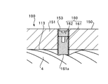
図5は、押圧手段の変形例1を示す断面図である。 FIG. 5 is a cross-sectional view showing a first modification of the pressing means.
図5に示す押圧手段160は、ケーブル導体(図5では接続される一方のケーブル導体4のみを示す)同士を接続する導体接続管100の本体部150に形成される取付孔153をネジ孔とする。この押圧手段160は、取付孔153(ネジ孔)に螺合するとともに先端部に食い込み部が形成されたボルト161と、このボルト161の上方に配置され、ネジ孔である取付孔153に螺合する止めボルト162とを有する。
The pressing means 160 shown in FIG. 5 has a mounting
すなわち、図5に示す押圧手段160は、押圧手段130にて説明したボルトと長さのみが異なりその他は同様に構成されたボルト161を螺合することにより、先端部161aでケーブル導体4、5を押圧する。押圧されたケーブル導体4、5は、それぞれの外周面の一部と反対側の外周面の一部で本体部150の内面に密着される。
That is, the pressing means 160 shown in FIG. 5 is screwed with a
ボルト161の押圧により、ケーブル導体4,5と本体部150とは、電気的に接続される。また、この状態を維持させるべく、止めボルト162をボルト孔である取付孔153に螺合して、止めボルト162の下端面をボルト161の上面に当接させる。
The
これにより、ボルト161のゆるみが防止され、ケーブル導体4、5のそれぞれを導体接続管100に確実に接触させた状態を維持させることができる。よって、導体接続管100により、ケーブル導体4、5同士は電気的、機械的に接続された状態を確実に維持される。
Thereby, loosening of the
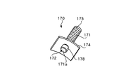
図6は、押圧手段の変形例2を示す斜視図である。 FIG. 6 is a perspective view showing a second modification of the pressing means.
図6に示す押圧手段170は、窪み先171aの六角穴付きボルト171と、ボルト171の先端部172に取り付けられ、ケーブル導体4、5の外周面に面接触して押圧する面接触板174と、止めナット部175とを有する。つまり、この押圧手段170は、本体部150内に挿入されるケーブル導体4、5の外周面の一部を押圧する窪み先171aよりも接触面積が広い面接触板174を有している。
The pressing means 170 shown in FIG. 6 includes a hexagon
詳細には、図7に示すボルト171の先端部172は、外周面に、本体部150の取付孔153に螺合される雄ねじ部が形成されるととともに上面に六角穴が形成されたボルト本体部175と一体的に形成されている。この先端部172は、円筒部176と、円筒部に連続してボルト本体部175の外径より小さい外径の雄ねじ部177とを有する。
In detail, the
円筒部176は、面接触板174の挿通孔に挿通され、雄ねじ部177に、挿通孔より外径が大きい止めナット部178が螺合されている。つまり、面接触板174は、ボルト171の先端部172に、ボルト軸を中心に回動自在に取り付けられている。なお、窪み先171aは止めナット部178から外部に臨むものである。
The
この面接触板174は、導電性を有し、ケーブル導体4、5の外周面に対応する形状を有する断面円弧状に形成されている。面接触板174は、先端部172の周囲、つまり、窪み先171aの周囲に配置され、ケーブル導体の外周面に対して、窪み先171aより接触面積が広い。
The
図7は、押圧手段の変形例2により押圧されるケーブル導体を示す断面図である。図7に示す導体接続管100aは、導体接続管100において押圧手段130に代えて押圧手段170を本体部150の取付孔153に取付けたものである。よって、導体接続管100aにおいて、導体接続管100と同様の構成については、同符号同名称を付して説明は省略する。
FIG. 7 is a cross-sectional view showing a cable conductor pressed by the second modification of the pressing means. A
この押圧手段170は、本体部150の内面113、123(図5では、内面113を示す)より内側に面接触板174を配置して、本体部150の周壁部151に形成された取付孔153に、ボルト171を螺合することにより取り付けられている。
This pressing means 170 has a mounting
この導体接続管100aでは、まず、開口部110、120を介して本体部150内にケーブル導体4を挿入する。そして、ボルト171を締めて先端部をより内方に突出させることにより、窪み先171a(食い込み部)によりケーブル導体4の外周面の一部4aに食い込みながらケーブル端部を押圧する。このとき、面接触板174はボルト171に対して回動自在に取り付けられているため、断面円弧状の内面が、対向するケーブル導体4、5の外周面の一部に沿って、外周面側に接近させることができる。
In the
そして、面接触板174は、ボルト171による押圧動作に伴い、内面をケーブル導体4、5の外周面の一部に当接させるとともに、その外周面の一部に面接触させながらケーブル導体4、5を押圧する。
The
押圧手段170により押圧されたケーブル導体4は、押圧手段分の反対側の外周面の一部で本体部150の内面113に密着されるとともに、面接触板174と密着する。
The
これによりケーブル導体4では、導体接続管100aに対し、押圧手段170による押圧される外周面の一部と反対側の外周面の一部が、本体部150の内面113と密着することにより電気的に接続される。
Thereby, in the
さらに、押圧手段170により押圧される部分(外周面の一部)で、面接触板174及びボルト171を介して電気的に接続される。これにより、ケーブル導体4と本体部150とをより、効果的に電気的に接続することができるとともに、導体4、5同士を、より効果的に電気的接続させることができる。
Furthermore, the portion (a part of the outer peripheral surface) pressed by the pressing means 170 is electrically connected via the
なお、面接触板174は、ボルト171に回動自在に取り付けられているが、面接触板174がケーブル導体4、5側に押圧された際には、ケーブル導体4、5によりボルト本体部175側に押圧されることとなる。これにより、面接触板174は、面接触板174の挿通孔内に位置する円筒部176より外径が大きいボルト本体部175に接触する。
The
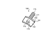
図8は、押圧手段の変形例3を示す斜視図である。 FIG. 8 is a perspective view showing a third modification of the pressing means.
図8に示す押圧手段180は、図6に示す押圧手段170の構成において、面接触板の構成のみ異なりその他の構成、作用効果は同様のものである。 The pressing means 180 shown in FIG. 8 differs from the pressing means 170 shown in FIG. 6 only in the configuration of the surface contact plate, and the other configurations and functions and effects are the same.
詳細には、図8に示す押圧手段180は、図6の押圧手段170において、ボルト171の先端部172に回動自在に取付られる面接触板174に替えて、面接触板181を回動自在に取り付けてなる。なお、面接触板181は、ボルト171に対して、変形例2の面接触板174と同様に、止めナット部178により抜け止めされている。
Specifically, the pressing means 180 shown in FIG. 8 is configured to rotate the
面接触板181は、変形例2と同様に、断面円弧状に形成された、本体板182と、本体板182の湾曲する両端辺に設けられた爪部183とを有する。この爪部183は、本体板182の内側に向かって突出して設けられ、導体接続管に取付られた押圧手段180を用いてケーブル導体4,5を押圧する際に、ケーブル導体4,5の外周面に食い込む。これにより、導体接続管におけるケーブル導体4、5の引っ張り強度の向上が図られる。
Similarly to the second modification, the
なお、この押圧手段180を導体接続管に用いて、ケーブル導体同士を接続する場合、押圧手段が取り付けられる本体部150の内面に面接触板181を収納可能なザグリ部を形成してもよい。
When connecting the cable conductors using the pressing means 180 as a conductor connecting tube, a counterbore part capable of accommodating the
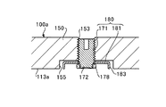
図9は、押圧手段の変形例3により押圧されるケーブル導体を示す図である。 FIG. 9 is a diagram illustrating the cable conductor pressed by the third modification of the pressing unit.
図9に示す導体接続管100aの本体部150の内面113aには、取付孔153に連通する凹部(ザグリ部)155が形成されている。
On the
凹部155は、面接触板181の爪部183の先端から、本体板182の裏面側までの長さ以上の長さを有する。つまり、凹部155は、押圧手段180を本体部150に取り付けた際に、爪部183の先端および止めナット部178の先端面が、本体部150の内面113と同じレベルか若しくは、本体部150の中心に対して、後退する位置となる深さとする。
The
これにより、押圧手段180を本体部150に取り付けた状態で、導体接続管100a両端の開口部からケーブル導体を挿入する場合でも、押圧手段180がケーブル導体挿入作業の邪魔にならない。そして、ケーブル導体を導体接続管100aの本体部150に挿入した後、ボルト171を締めることで面接触板181をケーブル導体の外周面側に接近させ、外周面に当接させる。
Thus, even when the cable conductor is inserted from the openings at both ends of the
そして、さらにボルト171をねじ込むことにより、面接触板181の爪部183がケーブル導体の外周面に食い込むとともに、ケーブル導体を押圧して、押圧部分と反対側の部分を本体部150の内面に当接させる。加えて、押圧手段180のねじ込みは、本体板182の内面をケーブル導体の外周面に接触させる。
Further, when the
よって、ケーブル導体同士を本体部150を介して確実に電気的に接続することができると共に、ケーブル導体の本体部150に対する引き抜き強度を向上させることができる。
Therefore, the cable conductors can be reliably electrically connected to each other via the
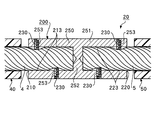
(実施の形態2)
図10は、本発明に係る実施の形態2の導体接続管を用いて導体を接続した導体接続部を示す図である。図11は、本発明の実施の形態2に係る導体接続管の本体部を示す部分断面図、図12は、図11の本体部の側面図である。
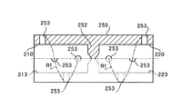
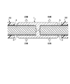
(Embodiment 2)
FIG. 10 is a diagram showing a conductor connecting portion in which conductors are connected using the conductor connecting tube according to the second embodiment of the present invention. FIG. 11 is a partial cross-sectional view showing a main body portion of a conductor connection pipe according to
図10に示す導体接続部20は、一対の電力ケーブル40、50を導体接続管200を介して接続してなる。導体接続管200は、接続されるケーブル導体4、5につき、4本の押圧手段、ここでは4本のボルトで接続している。
The
導体接続管200は、それぞれ導体4、5が露出する一対の電力ケーブル40、50の端部が両端の開口部210、220を介して挿入される筒状の本体部250と、本体部250内に挿入されたケーブル導体4、5を本体部250の内面213、223に押圧して電気的に接触させる押圧手段230とを有する。
The
この導体接続管200は、導体接続管100と比して押圧手段の数及びの配置位置のみ異なり、その他の構成は同様である。
This
本体部250は、例えば、金属などの導電性を有する部材により筒状に形成され、その内部中央に隔壁部252が設けられている。
The
また、この本体部250には、押圧手段230が設けられる取付孔253が複数形成されている。
The
この導体接続管200の取付孔253は、本体部250の周壁部の外面に沿う螺線R1状に形成されている。
The
取付孔253は、本体部250の周壁部251を連通するネジ取付孔である。取付孔253は、その軸線は本体部250の軸線と交わった直線上に形成されている。
The
また、これら取付孔253は、本体部250の同一円周上に配置されておらず、互いに、それぞれ対向しない位置に配置されている。ここでは、複数の取付孔253は、それぞれ周壁部251に仮想的に描く螺線R1上に位置して形成されている。
Further, these mounting
そして、これら取付孔253は、図12に示すように、本体部250の軸方向から見て、本体部250の円周上に等間隔に、ここでは4つ配置されている。言い換えれば、本体部250の軸心O1を中心に等角度の位置に形成されている。ここでは、取付孔253は、側面視して、互いに、軸心O1を中心に90°の角度を空けて配置されている。
As shown in FIG. 12, four mounting
取付孔253は、本体部250の軸方向から見て本体部250の円周上に等間隔あるいは、規則的に配置することで、電気的、機械的性能を維持することができる。
The mounting
そして、これら取付孔253のそれぞれには、開口部210、220を介して本体部250内部に左右から挿入されたケーブル導体4、5を本体部の内面213、223に押圧して電気的に接触させる押圧手段230が取り付けられている。
The
この取付孔253及び押圧手段230は、それぞれ実施の形態1に対応する取付孔153及び押圧手段130と同様に構成されるものであり、説明は省略する。
The mounting
この導体接続管200を用いたケーブル導体4、5の接続方法は、実施の形態1に対応する導体接続管100と略同様である。まず、開口部210、220から、接続すべきケーブル導体4、5を本体部250に挿入する。
The connection method of the
次いで、取付孔253に取付けられた押圧手段230が、本体部250に挿入されたケーブル導体4、5を押圧する。
Next, the pressing means 230 attached to the
詳細には、周壁部251のネジ孔(取付孔253)に螺合されたボルト(押圧手段230)をねじ込み、先端部を本体部250の内側に突出させる。この突出した先端部は、本体部250内において、対向するケーブル導体4、5の外周面に当接し、外周面を押圧する。
Specifically, a bolt (pressing means 230) screwed into the screw hole (attachment hole 253) of the
本体部250内で一部の外周面を押圧されたケーブル導体4、5では、押圧された部位と反対側の部位が、本体部250の内面213、223(詳細には、内面213、223において、取付孔253の軸線と同一軸線上に位置する部分)に当接する。また、ボルト先端部は、押圧手段230と同様に窪み先となっているため、ケーブル導体4、5に食い込む。
In the
これにより、ケーブル導体4、5は、導体接続管に電気的に接続される。
Thereby, the
この導体接続管200によれば、ケーブル導体4、5は、本体部250内においてボルトにより本体部250の内面213、223に押圧されて当接されるため、接続すべきケーブル導体4、5を本体部250に挿入して、ボルト(押圧手段230)を締めるだけで、簡単に電気的に接続することができる。
According to this
このため、例えば、道路下のマンホール内などのような狭い空間においても、従来と異なり、圧縮機を用いることなくケーブル導体4、5同士を電気的に接続することができる。また、本体部250内でボルト先端の食い込み部がケーブル導体4、5に食い込むことにより導体接続管200に対して、ケーブル導体4、5の引っ張り力を向上させることができる。
For this reason, for example, even in a narrow space such as in a manhole under a road, the
また、実施の形態2の押圧手段230は、実施の形態1の押圧手段130と同様に、変形例1、変形例2のボルトを適用することができる。 Further, the pressing means 230 of the second embodiment can apply the bolts of the first and second modifications, similarly to the pressing means 130 of the first embodiment.
この導体接続管200に変形例1及び変形例2の押圧手段を適用した際の効果は、各変形例1及び変形例2の作用効果と同様であるので説明は省略する。
Since the effects when the pressing means of the first and second modifications are applied to the
本発明に係る導体接続管は、狭い作業空間でも、電力ケーブル導体同士を、ケーブルの引っ張り強度を確保しつつ確実に、且つ、熟練を要さず容易に短時間で接続できる効果を有し、電力ケーブル導体を接続する導体接続管として有用である。 The conductor connection pipe according to the present invention has an effect that the power cable conductors can be reliably and easily connected in a short time without requiring skill, while securing the tensile strength of the cable, even in a narrow work space, It is useful as a conductor connection pipe for connecting a power cable conductor.
100、100a、200 導体接続管
130、160、170、230 押圧手段
132 食い込み部
150、250 本体部
151、251 周壁部
153、253 取付孔
174 面接触板
183 爪部(食い込み部)
100, 100a, 200
Claims (7)
前記本体部内に挿入された前記ケーブル端部を、前記ケーブル端部の外周面の一部を押圧して、前記本体部の内面に当接させる押圧手段とを有することを特徴とする導体接続管。 A main body portion into which a cable end portion where a conductor of the power cable is exposed is inserted;
A conductor connecting pipe comprising pressing means for pressing a part of the outer peripheral surface of the cable end portion into contact with the inner surface of the main body portion of the cable end portion inserted into the main body portion. .
前記複数の押圧手段は、前記本体部の同一円周上に互いに対向しない位置に配置されていることを特徴とする請求項1記載の導体接続管。 A plurality of the pressing means are provided,
The conductor connecting pipe according to claim 1, wherein the plurality of pressing means are arranged at positions that do not face each other on the same circumference of the main body portion.
前記複数の押圧手段は、本体部に螺線上に取り付けられていることを特徴とする請求項1記載の導体接続管。 A plurality of the pressing means are provided,
The conductor connecting pipe according to claim 1, wherein the plurality of pressing means are attached to the main body on a spiral.
前記導体接続管の本体部に、前記電力ケーブルの端部を挿入し、
次いで、前記本体部に挿入された前記ケーブル端部を押圧手段により押圧して、前記ケーブル端部を前記本体部の内面に当接させることを特徴とする電力ケーブルの接続方法。 A connection method for connecting a cable end portion where a conductor is exposed of a power cable using the conductor connection pipe according to claim 1,
Insert the end of the power cable into the main body of the conductor connection tube,
Next, the cable end inserted into the main body is pressed by pressing means, and the cable end is brought into contact with the inner surface of the main body.
導電性を有し、前記ケーブル端部が挿入される本体部と、
前記本体部に挿入された前記ケーブル端部を、前記ケーブル端部の外周面の一部を押圧して、前記本体部内面に当接させる押圧手段とを有することを特徴とする導体接続部。 The end of the cable where the conductor is exposed in the power cable;
A main body having conductivity and into which the cable end is inserted;
A conductor connecting portion having pressing means for pressing the cable end portion inserted into the main body portion with a part of the outer peripheral surface of the cable end portion to contact the inner surface of the main body portion.
Priority Applications (1)
| Application Number | Priority Date | Filing Date | Title |
|---|---|---|---|
| JP2004103884A JP2005293898A (en) | 2004-03-31 | 2004-03-31 | Conductor connecting pipe and connection method |
Applications Claiming Priority (1)
| Application Number | Priority Date | Filing Date | Title |
|---|---|---|---|
| JP2004103884A JP2005293898A (en) | 2004-03-31 | 2004-03-31 | Conductor connecting pipe and connection method |
Publications (1)
| Publication Number | Publication Date |
|---|---|
| JP2005293898A true JP2005293898A (en) | 2005-10-20 |
Family
ID=35326620
Family Applications (1)
| Application Number | Title | Priority Date | Filing Date |
|---|---|---|---|
| JP2004103884A Pending JP2005293898A (en) | 2004-03-31 | 2004-03-31 | Conductor connecting pipe and connection method |
Country Status (1)
| Country | Link |
|---|---|
| JP (1) | JP2005293898A (en) |
Cited By (5)
| Publication number | Priority date | Publication date | Assignee | Title |
|---|---|---|---|---|
| JP2007250483A (en) * | 2006-03-20 | 2007-09-27 | Viscas Corp | Cable conductor connection method, connection portion, and conductor connection sleeve |
| JP2010180957A (en) * | 2009-02-05 | 2010-08-19 | Hiroyasu Minayoshi | Connection tool and connection method using the connection tool |
| WO2017030271A1 (en) * | 2015-08-14 | 2017-02-23 | 엘에스전선 주식회사 | Connection structure of cables, method for connecting cables and conductor sleeve used therein for cable connector |
| WO2019054569A1 (en) * | 2017-09-12 | 2019-03-21 | 엘에스전선 주식회사 | Conductor connection structure of power cable, conductor connection method of power cable, and conductor connection apparatus of power cable |
| CN114256673A (en) * | 2020-09-22 | 2022-03-29 | 中航光电科技股份有限公司 | A kind of interface unit |
-
2004
- 2004-03-31 JP JP2004103884A patent/JP2005293898A/en active Pending
Cited By (5)
| Publication number | Priority date | Publication date | Assignee | Title |
|---|---|---|---|---|
| JP2007250483A (en) * | 2006-03-20 | 2007-09-27 | Viscas Corp | Cable conductor connection method, connection portion, and conductor connection sleeve |
| JP2010180957A (en) * | 2009-02-05 | 2010-08-19 | Hiroyasu Minayoshi | Connection tool and connection method using the connection tool |
| WO2017030271A1 (en) * | 2015-08-14 | 2017-02-23 | 엘에스전선 주식회사 | Connection structure of cables, method for connecting cables and conductor sleeve used therein for cable connector |
| WO2019054569A1 (en) * | 2017-09-12 | 2019-03-21 | 엘에스전선 주식회사 | Conductor connection structure of power cable, conductor connection method of power cable, and conductor connection apparatus of power cable |
| CN114256673A (en) * | 2020-09-22 | 2022-03-29 | 中航光电科技股份有限公司 | A kind of interface unit |
Similar Documents
| Publication | Publication Date | Title |
|---|---|---|
| US6764354B2 (en) | Submersible electrical set-screw connector | |
| US7882629B2 (en) | Electrical connector for aluminum conductor composite core (ACCC) cable | |
| US7575485B2 (en) | Knurled inner sleeve for a cable connector | |
| KR102776768B1 (en) | Elbow connection operation device | |
| US11942748B2 (en) | Method for establishing a connection between an electrical connecting element for a motor vehicle on-board network and a cable of the motor vehicle on-board network | |
| CA2720109C (en) | Bonding and grounding clamp/connector for electrode conductors | |
| US20160226158A1 (en) | Assembly and method for electrical splice connection of cables | |
| US5630737A (en) | Junction connector for permanently connecting electrical cables | |
| CN104396089A (en) | Electric connection system | |
| JP2000513481A (en) | Power line cable connector | |
| JP2014002994A (en) | Coupler for power cable | |
| CN104682030A (en) | Line cleat of distribution line | |
| JP2005293898A (en) | Conductor connecting pipe and connection method | |
| EP3499646B1 (en) | Electrical connector and connector system using the same | |
| CN204348943U (en) | A kind of wire clamp of distribution line | |
| JPH08149679A (en) | Power cable conductor connection device | |
| JP2009151951A (en) | Wire connector | |
| US3340351A (en) | Dead-end connector | |
| KR20190050544A (en) | Connecting Structure of Power Cable Conductor And Connecting Method Of The Same | |
| JP2016162628A (en) | Connector-equipped electric wire, connector structure, and manufacturing method of connector structure | |
| JP2003249281A (en) | Wire connection terminal and wire connection structure | |
| US20240421508A1 (en) | Mechanical connector for connecting an electrical cable | |
| CA1283467C (en) | Electrical connector | |
| KR101103939B1 (en) | Maintenance method and structure of transmission tower buried ship | |
| JP2019092262A (en) | Connection structure for electric wire |
Legal Events
| Date | Code | Title | Description |
|---|---|---|---|
| A621 | Written request for application examination |
Free format text: JAPANESE INTERMEDIATE CODE: A621 Effective date: 20051011 |
|
| A871 | Explanation of circumstances concerning accelerated examination |
Free format text: JAPANESE INTERMEDIATE CODE: A871 Effective date: 20051011 |
|
| A131 | Notification of reasons for refusal |
Free format text: JAPANESE INTERMEDIATE CODE: A131 Effective date: 20051206 |
|
| A521 | Written amendment |
Free format text: JAPANESE INTERMEDIATE CODE: A523 Effective date: 20060203 |
|
| A02 | Decision of refusal |
Free format text: JAPANESE INTERMEDIATE CODE: A02 Effective date: 20060314 |