JP2005293867A - Catalyst layer transfer sheet and solid electrolyte membrane with catalyst layer - Google Patents
Catalyst layer transfer sheet and solid electrolyte membrane with catalyst layer Download PDFInfo
- Publication number
- JP2005293867A JP2005293867A JP2004102856A JP2004102856A JP2005293867A JP 2005293867 A JP2005293867 A JP 2005293867A JP 2004102856 A JP2004102856 A JP 2004102856A JP 2004102856 A JP2004102856 A JP 2004102856A JP 2005293867 A JP2005293867 A JP 2005293867A
- Authority
- JP
- Japan
- Prior art keywords
- catalyst layer
- platinum
- photocatalyst
- transfer sheet
- water
- Prior art date
- Legal status (The legal status is an assumption and is not a legal conclusion. Google has not performed a legal analysis and makes no representation as to the accuracy of the status listed.)
- Granted
Links
Images


Classifications
-
- Y—GENERAL TAGGING OF NEW TECHNOLOGICAL DEVELOPMENTS; GENERAL TAGGING OF CROSS-SECTIONAL TECHNOLOGIES SPANNING OVER SEVERAL SECTIONS OF THE IPC; TECHNICAL SUBJECTS COVERED BY FORMER USPC CROSS-REFERENCE ART COLLECTIONS [XRACs] AND DIGESTS
- Y02—TECHNOLOGIES OR APPLICATIONS FOR MITIGATION OR ADAPTATION AGAINST CLIMATE CHANGE
- Y02E—REDUCTION OF GREENHOUSE GAS [GHG] EMISSIONS, RELATED TO ENERGY GENERATION, TRANSMISSION OR DISTRIBUTION
- Y02E60/00—Enabling technologies; Technologies with a potential or indirect contribution to GHG emissions mitigation
- Y02E60/30—Hydrogen technology
- Y02E60/50—Fuel cells
-
- Y—GENERAL TAGGING OF NEW TECHNOLOGICAL DEVELOPMENTS; GENERAL TAGGING OF CROSS-SECTIONAL TECHNOLOGIES SPANNING OVER SEVERAL SECTIONS OF THE IPC; TECHNICAL SUBJECTS COVERED BY FORMER USPC CROSS-REFERENCE ART COLLECTIONS [XRACs] AND DIGESTS
- Y02—TECHNOLOGIES OR APPLICATIONS FOR MITIGATION OR ADAPTATION AGAINST CLIMATE CHANGE
- Y02P—CLIMATE CHANGE MITIGATION TECHNOLOGIES IN THE PRODUCTION OR PROCESSING OF GOODS
- Y02P70/00—Climate change mitigation technologies in the production process for final industrial or consumer products
- Y02P70/50—Manufacturing or production processes characterised by the final manufactured product
Landscapes
- Inert Electrodes (AREA)
- Fuel Cell (AREA)
Abstract
【課題】優れた親水性及び撥水性を兼備する電極−電解質膜接合体を製造するための、触媒層転写シート及び触媒層付き固体電解質膜を提供する。
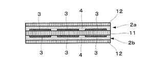
【解決手段】触媒層転写シートは、基材シートの一方面上に、(a)白金又は白金化合物触媒を担持した炭素粒子、(b)水素イオン伝導性高分子物質及び(c)エネルギー照射により水に対する濡れ性が撥水性から親水性に変化する物質を含有する白金含有触媒層が形成されている。該触媒層転写シートの白金含有触媒層面にエネルギーを照射することにより、白金含有触媒層面に親水性領域を形成できる。この触媒層転写シートを用い、該転写シートの触媒層を固体電解質膜11に転写することにより、優れた親水性3及び撥水性4を兼備する触媒層−電解質膜接合体を製造できる。
【選択図】図10A catalyst layer transfer sheet and a solid electrolyte membrane with a catalyst layer for producing an electrode-electrolyte membrane assembly having both excellent hydrophilicity and water repellency are provided.
A catalyst layer transfer sheet comprises: (a) carbon particles carrying platinum or a platinum compound catalyst, (b) a hydrogen ion conductive polymer substance, and (c) energy irradiation on one side of a substrate sheet. A platinum-containing catalyst layer containing a substance whose wettability to water changes from water repellency to hydrophilicity is formed. By irradiating the platinum-containing catalyst layer surface of the catalyst layer transfer sheet with energy, a hydrophilic region can be formed on the platinum-containing catalyst layer surface. By using this catalyst layer transfer sheet and transferring the catalyst layer of the transfer sheet to the solid electrolyte membrane 11, a catalyst layer-electrolyte membrane assembly having both excellent hydrophilicity 3 and water repellency 4 can be produced.
[Selection] Figure 10
Description
本発明は、触媒層転写シート及び触媒層付き固体電解質膜に関する。 The present invention relates to a catalyst layer transfer sheet and a solid electrolyte membrane with a catalyst layer.
燃料電池は、電解質膜の両面に触媒層を配置した構成からなり、水素及び酸素の電気化学反応により発電する。そのため、発電時に発生するのは水のみである。燃料電池は、従来の内燃機関と異なり、二酸化炭素等の環境負荷ガスを発生しないため、次世代のクリーンエネルギーシステムとして注目されている。 A fuel cell has a configuration in which catalyst layers are arranged on both sides of an electrolyte membrane, and generates power by an electrochemical reaction of hydrogen and oxygen. Therefore, only water is generated during power generation. Unlike conventional internal combustion engines, fuel cells do not generate environmentally harmful gases such as carbon dioxide, and thus are attracting attention as next-generation clean energy systems.
燃料電池は、燃料である水素ガスと酸化剤ガスである酸素により以下の反応を起こさせることにより、起電力を発生させている。 The fuel cell generates an electromotive force by causing the following reaction with hydrogen gas as a fuel and oxygen as an oxidant gas.
燃料極: H2 → 2H++2e-
空気極: 2H++2e-+(1/2)O2 → H2O
燃料電池は、発電の際に発熱を伴い、電解質膜内の温度上昇により膜内の含水量が低下し、そのためにイオン伝導性が低下する。
Fuel electrode: H 2 → 2H + + 2e −
Air electrode: 2H + + 2e − + (1/2) O 2 → H 2 O
The fuel cell generates heat during power generation, and the water content in the membrane decreases due to the temperature increase in the electrolyte membrane, and therefore the ionic conductivity decreases.
燃料極は、電解質膜のドライアップを防ぐための水分保持性(親水性)と、H2の吸着サイトを確保するためのある程度の撥水性を有していることが必要である。 The fuel electrode is required to have moisture retention (hydrophilicity) for preventing the electrolyte membrane from drying up and a certain degree of water repellency for securing an adsorption site for H 2 .
一方、空気極側では電池反応に伴って水を生成している。この水は、逆浸透により燃料極側へ水分を補給する役目を果たすが、高電流密度域での多量の水分発生等により、空気極のO2吸着サイトを埋めてしまいフラッディングを起こす原因となる。このため、空気極は、O2の吸着サイトを確保するための撥水性を備えていることが必要となる。 On the other hand, water is generated along with the battery reaction on the air electrode side. This water plays a role of replenishing water to the fuel electrode side by reverse osmosis. However, due to generation of a large amount of water in a high current density region, it fills the O 2 adsorption site of the air electrode and causes flooding. . For this reason, the air electrode is required to have water repellency for securing an O 2 adsorption site.
このような観点から、空気極に適度の撥水性を付与するために、例えば、電極−電解質膜接合体において、固体高分子電解質膜上に電極触媒層が形成されている部分と電極触媒層が形成されていない部分とを設ける方法(例えば、特許文献1等)、(2)触媒層を複数個に分割し、分割した複数の触媒層は少なくとも2種類以上の親水性の異なる材料からなり、触媒層と触媒層の隙間にはフッ素樹脂等からなる撥水剤を充填する方法(例えば、特許文献2等)等が提案されている。 From this point of view, in order to impart appropriate water repellency to the air electrode, for example, in the electrode-electrolyte membrane assembly, the portion where the electrode catalyst layer is formed on the solid polymer electrolyte membrane and the electrode catalyst layer (2) The catalyst layer is divided into a plurality of parts, and the plurality of divided catalyst layers are made of at least two kinds of hydrophilic materials different from each other, A method of filling a gap between the catalyst layer and the catalyst layer with a water repellent made of a fluororesin or the like (for example, Patent Document 2) has been proposed.
また、燃料極に適度の親水性を付与するために、(3)カーボンペーパー等のガス拡散層表面に酸化チタン等の光触媒性親水性層を設ける方法(例えば、特許文献3等)、(4)多孔質プレート中に酸化チタン等の親水性材料を充填する方法(例えば、特許文献4等)等が提案されている。 In order to impart moderate hydrophilicity to the fuel electrode, (3) a method of providing a photocatalytic hydrophilic layer such as titanium oxide on the surface of a gas diffusion layer such as carbon paper (for example, Patent Document 3), (4 ) A method of filling a porous plate with a hydrophilic material such as titanium oxide (for example, Patent Document 4) has been proposed.
しかしながら、これらの特許文献に記載されている燃料電池では、親水性及び撥水性の双方に優れるという相反する要求を同時に解決することは困難である。従って、上記(1)〜(4)の方法では、所望の電池性能を備えた燃料電池を製造し得ない。
本発明の課題は、優れた親水性及び撥水性を兼備する電極−電解質膜接合体を製造するための、触媒層付き固体電解質膜及び触媒層転写シートを提供することにある。 An object of the present invention is to provide a solid electrolyte membrane with a catalyst layer and a catalyst layer transfer sheet for producing an electrode-electrolyte membrane assembly having both excellent hydrophilicity and water repellency.
本発明者は、上記課題を解決するために鋭意研究を重ねてきた。その結果、基材シート上に特定の白金含有触媒層を形成した触媒層転写シートを用い、該白金含有触媒層にエネルギーを照射して、白金含有触媒層のエネルギー照射部分を親水性に変化させた後、該転写シートの触媒層を固体電解質膜に転写することにより、所望の触媒層付き固体電解質膜が得られることを見い出した。本発明は、斯かる知見に基づき完成されたものである。 The present inventor has intensively studied to solve the above problems. As a result, using a catalyst layer transfer sheet in which a specific platinum-containing catalyst layer is formed on a base sheet, the platinum-containing catalyst layer is irradiated with energy, and the energy-irradiated portion of the platinum-containing catalyst layer is changed to be hydrophilic. Thereafter, it was found that a desired solid electrolyte membrane with a catalyst layer can be obtained by transferring the catalyst layer of the transfer sheet to the solid electrolyte membrane. The present invention has been completed based on such findings.
本発明は、下記1〜12に示す発明を提供する。
1.基材シートの一方面上に白金含有触媒層が形成された触媒層転写シートであって、
前記白金含有触媒層が、(a)白金又は白金化合物触媒を担持した炭素粒子、(b)水素イオン伝導性高分子物質及び(c)エネルギー照射により水に対する濡れ性が撥水性から親水性に変化する物質を含有している、
触媒層転写シート。
2.(c)のエネルギー照射により水に対する濡れ性が撥水性から親水性に変化する物質が、オルガノポリシロキサンである上記1に記載の転写シート。
3.前記オルガノポリシロキサンが、フルオロアルキル基を含有するポリシロキサンである上記2に記載の転写シート。
4.前記白金含有触媒層には光触媒が含有されている上記1〜3のいずれかに記載の転写シート。
5.前記白金含有触媒層は、親水性領域と撥水性領域とを有している、上記1〜4のいずれかに記載の転写シート。
6.(i)基材シートの一方面上に(a)白金又は白金化合物触媒を担持した炭素粒子、(b)水素イオン伝導性高分子物質及び(c)エネルギー照射により水に対する濡れ性が撥水性から親水性に変化する物質を含有する白金含有触媒層を形成する工程、及び
(ii)白金含有触媒層に光触媒含有層を接触させ、光触媒含有層を通じて白金含有触媒層にエネルギーを照射する工程
を備えた、上記5に記載の触媒層転写シートの製造方法。
7.(i)基材シートの一方面上に(a)白金又は白金化合物触媒を担持した炭素粒子、(b)水素イオン伝導性高分子物質、(c)エネルギー照射により水に対する濡れ性が撥水性から親水性に変化する物質及び(d)光触媒を含有する白金含有触媒層を形成する工程、及び
(ii)光触媒を含有する白金含有触媒層にエネルギーを照射する工程
を備えた、上記5に記載の触媒層転写シートの製造方法。
8.固体電解質膜の一方面上又は両面上に白金含有触媒層が形成された電解質膜であって、
前記白金含有触媒層が、(a)白金又は白金化合物触媒を担持した炭素粒子、(b)水素イオン伝導性高分子物質及び(c)エネルギー照射により水に対する濡れ性が撥水性から親水性に変化する物質を含有している、
触媒層付き固体電解質膜。
9.(c)のエネルギー照射により水に対する濡れ性が撥水性から親水性に変化する物質が、オルガノポリシロキサンである上記8に記載の固体電解質膜。
10.前記オルガノポリシロキサンが、フルオロアルキル基を含有するポリシロキサンである上記9に記載の固体電解質膜。
11.前記白金含有触媒層には光触媒が含有されている上記8〜10のいずれかに記載の固体電解質膜。
12.前記白金含有触媒層は、親水性領域と撥水性領域とを有している、上記8〜11のいずれかに記載の固体電解質膜。
The present invention provides the
1. A catalyst layer transfer sheet in which a platinum-containing catalyst layer is formed on one side of a base sheet,
The platinum-containing catalyst layer has (a) carbon particles carrying platinum or a platinum compound catalyst, (b) a hydrogen ion conductive polymer substance, and (c) water wettability changes from water-repellent to hydrophilic by energy irradiation. Contains substances that
Catalyst layer transfer sheet.
2. 2. The transfer sheet as described in 1 above, wherein the substance whose wettability to water changes from water repellency to hydrophilicity by energy irradiation of (c) is an organopolysiloxane.
3. 3. The transfer sheet according to 2 above, wherein the organopolysiloxane is a polysiloxane containing a fluoroalkyl group.
4). 4. The transfer sheet according to any one of 1 to 3, wherein the platinum-containing catalyst layer contains a photocatalyst.
5). The transfer sheet according to any one of 1 to 4, wherein the platinum-containing catalyst layer has a hydrophilic region and a water-repellent region.
6). (i) (a) carbon particles carrying platinum or a platinum compound catalyst on one side of the base sheet, (b) hydrogen ion conductive polymer substance, and (c) water wettability due to energy irradiation due to water repellency Forming a platinum-containing catalyst layer containing a substance that changes to hydrophilicity; and
(ii) The method for producing a catalyst layer transfer sheet as described in 5 above, comprising the steps of bringing the photocatalyst containing layer into contact with the platinum containing catalyst layer and irradiating the platinum containing catalyst layer with energy through the photocatalyst containing layer.
7). (i) (a) carbon particles carrying platinum or a platinum compound catalyst on one side of the substrate sheet, (b) hydrogen ion conductive polymer material, (c) water wettability due to energy irradiation due to water repellency Forming a platinum-containing catalyst layer containing a substance that changes to hydrophilicity and (d) a photocatalyst; and
(ii) The method for producing a catalyst layer transfer sheet according to 5 above, comprising a step of irradiating energy to a platinum-containing catalyst layer containing a photocatalyst.
8). An electrolyte membrane in which a platinum-containing catalyst layer is formed on one side or both sides of a solid electrolyte membrane,
The platinum-containing catalyst layer has (a) carbon particles carrying platinum or a platinum compound catalyst, (b) a hydrogen ion conductive polymer substance, and (c) water wettability changes from water-repellent to hydrophilic by energy irradiation. Contains substances that
Solid electrolyte membrane with catalyst layer.
9. 9. The solid electrolyte membrane according to 8 above, wherein the substance whose wettability to water changes from water repellency to hydrophilicity by energy irradiation of (c) is an organopolysiloxane.
10. 10. The solid electrolyte membrane according to 9 above, wherein the organopolysiloxane is a polysiloxane containing a fluoroalkyl group.
11. The solid electrolyte membrane according to any one of 8 to 10, wherein the platinum-containing catalyst layer contains a photocatalyst.
12 The solid electrolyte membrane according to any one of 8 to 11 above, wherein the platinum-containing catalyst layer has a hydrophilic region and a water-repellent region.
触媒層転写シート
本発明の触媒層転写シートは、基材シートの一方面上に、白金含有触媒層が形成されている。該白金含有触媒層は、(a)白金又は白金化合物触媒を担持した炭素粒子、(b)水素イオン伝導性高分子物質及び(c)エネルギー照射により水に対する濡れ性が撥水性から親水性に変化する物質を含有している。
Catalyst layer transfer sheet In the catalyst layer transfer sheet of the present invention, a platinum-containing catalyst layer is formed on one surface of a base sheet. The platinum-containing catalyst layer has (a) carbon particles carrying platinum or a platinum compound catalyst, (b) a hydrogen ion conductive polymer substance, and (c) the water wettability changes from water repellent to hydrophilic by energy irradiation. Contains substances that
本発明の触媒層転写シートの一実施態様を示す断面図を図1に示す。図1において、1は基材シート、2は白金含有触媒層である。 A sectional view showing one embodiment of the catalyst layer transfer sheet of the present invention is shown in FIG. In FIG. 1, 1 is a base material sheet, 2 is a platinum containing catalyst layer.
基材シート
基材シートとしては、例えば、ポリイミド、ポリエチレンテレフタレート、ポリパルバン酸アラミド、ポリアミド(ナイロン)、ポリサルホン、ポリエーテルサルホン、ポリフェニレンサルファイド、ポリエーテル・エーテルケトン、ポリエーテルイミド、ポリアリレート、ポリエチレンナフタレート等の高分子フィルムを挙げることができる。
As the base sheet , for example, polyimide, polyethylene terephthalate, polyparvanic acid aramid, polyamide (nylon), polysulfone, polyethersulfone, polyphenylene sulfide, polyether ether ketone, polyetherimide, polyarylate, polyethylene naphthalate Examples thereof include polymer films such as phthalate.
また、エチレンテトラフルオロエチレン共重合体(ETFE)、テトラフルオロエチレン−ヘキサフルオロプロピレン共重合体(FEP)、テトラフルオロパーフルオロアルキルビニルエーテル共重合体(PFA)、ポリテトラフルオロエチレン(PTFE)等の耐熱性フッ素樹脂を用いることもできる。 In addition, heat resistance of ethylene tetrafluoroethylene copolymer (ETFE), tetrafluoroethylene-hexafluoropropylene copolymer (FEP), tetrafluoroperfluoroalkyl vinyl ether copolymer (PFA), polytetrafluoroethylene (PTFE), etc. Fluorine resin can also be used.
更に、基材シートは、高分子フィルム以外に、アート紙、コート紙、軽量コート紙等の塗工紙、ノート用紙、コピー用紙等の非塗工紙等の紙であってもよい。 Further, the base sheet may be paper such as art paper, coated paper, coated paper such as lightweight coated paper, non-coated paper such as notebook paper, copy paper, etc. in addition to the polymer film.
基材シートの厚さは、取り扱い性及び経済性の観点から、通常6〜100μm程度、好ましくは6〜30μm程度、より好ましくは6〜15μm程度とするのがよい。 The thickness of the base sheet is usually about 6 to 100 μm, preferably about 6 to 30 μm, and more preferably about 6 to 15 μm from the viewpoints of handleability and economy.
従って、基材シートとしては、安価で入手が容易な高分子フィルムが好ましく、ポリエチレンテレフタレート等がより好ましい。 Therefore, as a base material sheet, an inexpensive and easily available polymer film is preferable, and polyethylene terephthalate or the like is more preferable.
白金含有触媒層
白金含有触媒層(カソード触媒層及びアノード触媒層)は、(a)白金又は白金化合物触媒を担持した炭素粒子、(b)水素イオン伝導性高分子物質及び(c)エネルギー照射により水に対する濡れ性が撥水性から親水性に変化する物質を含有する。
Platinum-containing catalyst layer The platinum-containing catalyst layer (cathode catalyst layer and anode catalyst layer) comprises (a) carbon particles carrying platinum or a platinum compound catalyst, (b) a hydrogen ion conductive polymer substance, and (c) energy irradiation. Contains a substance whose wettability to water changes from water-repellent to hydrophilic.
(a)の白金又は白金化合物触媒を担持した炭素粒子としては、公知のものを広く使用できる。白金化合物としては、例えば、ルテニウム、パラジウム、ロジウム、ニッケル、モリブデン、イリジウム、鉄等からなる群から選ばれる少なくとも1種の金属と白金との合金等が挙げられる。 As the carbon particles carrying platinum or a platinum compound catalyst (a), known particles can be widely used. Examples of the platinum compound include an alloy of platinum and at least one metal selected from the group consisting of ruthenium, palladium, rhodium, nickel, molybdenum, iridium, iron and the like.
カソード触媒層に含まれる触媒は、通常、白金であり、アノード触媒層に含まれる触媒は、通常、上記金属と白金との合金である。 The catalyst contained in the cathode catalyst layer is usually platinum, and the catalyst contained in the anode catalyst layer is usually an alloy of the above metal and platinum.
斯かる触媒は、反応面積を大きくするために、通常、該触媒を微粉化し、これをカーボン粉、カーボンナノチューブ等に担持させている。 In order to increase the reaction area, such a catalyst is usually pulverized and supported on carbon powder, carbon nanotubes or the like.
(b)の水素イオン伝導性高分子電解質としては、例えば、パーフルオロスルホン酸系のフッ素イオン交換樹脂、より具体的には、炭化水素系イオン交換膜のC−H結合をフッ素で置換したパーフルオロカーボンスルホン酸系ポリマー(PFS系ポリマー)等が挙げられる。電気陰性度の高いフッ素原子を導入することで、化学的に非常に安定し、スルホン酸基の解離度が高く、高いイオン伝導性が実現できる。このような水素イオン伝導性高分子電解質の具体例としては、デュポン社製の「Nafion」、旭硝子(株)製の「Flemion」、旭化成(株)製の「Aciplex」、ゴア(Gore)社製の「Gore Select」等が挙げられる。 The hydrogen ion conductive polymer electrolyte of (b) is, for example, a perfluorosulfonic acid-based fluorine ion exchange resin, more specifically, a perfluorosulfonic acid-based permeation membrane in which the C—H bond of the hydrocarbon ion-exchange membrane is substituted with fluorine. Examples thereof include fluorocarbon sulfonic acid polymers (PFS polymers). By introducing a fluorine atom having high electronegativity, it is chemically very stable, the dissociation degree of the sulfonic acid group is high, and high ion conductivity can be realized. Specific examples of such a hydrogen ion conductive polymer electrolyte include “Nafion” manufactured by DuPont, “Flemion” manufactured by Asahi Glass Co., Ltd., “Aciplex” manufactured by Asahi Kasei Co., Ltd., and Gore manufactured by Gore. "Gore Select" and so on.
(c)のエネルギー照射により水に対する濡れ性が撥水性から親水性に変化する物質(以下、「濡れ性変化物質」という)としては、エネルギー照射(露光)により接触する光触媒により濡れ性が変化する材料であって、且つ光触媒の作用によって劣化、分解し難い主鎖を有するものである限り、公知のものを広く使用できる。このような材料としては、例えば、オルガノポリシロキサンを挙げることができる。 As the substance (c) whose wettability with respect to water changes from water repellency to hydrophilicity (hereinafter referred to as “wetability changing substance”), the wettability changes depending on the photocatalyst that is contacted by energy irradiation (exposure). As long as it is a material and has a main chain that is hardly deteriorated or decomposed by the action of the photocatalyst, known materials can be widely used. An example of such a material is organopolysiloxane.
オルガノポリシロキサンとしては、例えば、(1)ゾルゲル反応等によりハロゲノシラン、アルコキシシラン等を加水分解、重縮合して大きな強度を発揮するオルガノポリシロキサン、(2)撥水牲及び撥油性に優れた反応性シリコーンを架橋したオルガノポリシロキサン等を挙げることができる。 Examples of organopolysiloxanes include (1) organopolysiloxanes that exhibit high strength by hydrolyzing and polycondensing halogenosilane, alkoxysilane, etc. by sol-gel reaction, etc. (2) excellent in water repellency and oil repellency. Mention may be made of organopolysiloxanes cross-linked with reactive silicones.
上記(1)のオルガノポリシロキサンとしては、一般式:
YnSiX(4-n) (A)
(ここで、Yはアルキル基、フルオロアルキル基、ビニル基、アミノ基、フェニル基又はエポキシ基を示し、Xはアルコキシ基、アセチル基又はハロゲンを示す。nは0〜3の整数を示す。)
で表される珪素化合物の1種もしくは2種以上の加水分解縮合物又は共加水分解縮合物であるオルガノポリシロキサンであることが好ましい。
The organopolysiloxane (1) has the general formula:
Y n SiX (4-n) (A)
(Here, Y represents an alkyl group, a fluoroalkyl group, a vinyl group, an amino group, a phenyl group or an epoxy group, X represents an alkoxy group, an acetyl group or a halogen. N represents an integer of 0 to 3.)
It is preferable that it is the organopolysiloxane which is a 1 type, or 2 or more types of hydrolytic condensate or cohydrolysis condensate of the silicon compound represented by these.
上記Yで示される各基の炭素数は1〜20の範囲内であることが好ましく、また、Xで示されるアルコキシ基は、メトキシ基、エトキシ基、n−プロポキシ基、イソプロポキシ基、n−ブトキシ基等の炭素数1〜4のアルコキシ基が好ましい。 The number of carbon atoms of each group represented by Y is preferably in the range of 1 to 20, and the alkoxy group represented by X is a methoxy group, an ethoxy group, an n-propoxy group, an isopropoxy group, n- C1-C4 alkoxy groups, such as a butoxy group, are preferable.
本発明においては、オルガノポリシロキサンが、フルオロアルキル基を含有するオルガノポリシロキサンであることが好ましい。 In the present invention, the organopolysiloxane is preferably an organopolysiloxane containing a fluoroalkyl group.
フルオロアルキル基を含有するオルガノポリシロキサンとしては、公知のフッ素系シランカップリング剤を広く使用でき、その具体例としては、例えば、下記に示すフルオロアルキルシランの1種もしくは2種以上の加水分解縮合物又は共加水分解縮合物が挙げられる。 As the organopolysiloxane containing a fluoroalkyl group, known fluorine-based silane coupling agents can be widely used. Specific examples thereof include, for example, one or more hydrolytic condensations of the following fluoroalkylsilanes. Product or cohydrolyzed condensate.
CF3(CF2)3CH2CH2Si(OCH3)3;
CF3(CF2)5CH2CH2Si(OCH3)3;
CF3(CF2)7CH2CH2Si(OCH3)3;
CF3(CF2)9CH2CH2Si(OCH3)3;
(CF3)2CF(CF2)4CH2CH2Si(OCH3)3;
(CF3)2CF(CF2)6CH2CH2Si(OCH3)3;
(CF3)2CF(CF2)8CH2CH2Si(OCH3)3;
CF3(C6H4)C2H4Si(OCH3)3;
CF3(CF2)3(C6H4)C2H4Si(OCH3)3;
CF3(CF2)5(C6H4)C2H4Si(OCH3)3;
CF3(CF2)7(C6H4)C2H4Si(OCH3)3;
CF3(CF2)3CH2CH2SiCH3(OCH3)2;
CF3(CF2)5CH2CH2SiCH3(OCH3)2;
CF3(CF2)7CH2CH2SiCH3(OCH3)2;
CF3(CF2)9CH2CH2SiCH3(OCH3)2;
(CF3)2CF(CF2)4CH2CH2SiCH3(OCH3)2;
(CF3)2CF(CF2)6CH2CH2SiCH3(OCH3)2;
(CF3)2CF(CF2)8CH2CH2SiCH3(OCH3)2;
CF3(C6H4)C2H4SiCH3(OCH3)2;
CF3(CF2)3(C6H4)C2H4SiCH3(OCH3)2;
CF3(CF2)5(C6H4)C2H4SiCH3(OCH3)2;
CF3(CF2)7(C6H4)C2H4SiCH3(OCH3)2;
CF3(CF2)3CH2CH2Si(OCH2CH3)3;
CF3(CF2)5CH2CH2Si(OCH2CH3)3;
CF3(CF2)7CH2CH2Si(OCH2CH3)3;及び
CF3(CF2)9CH2CH2Si(OCH2CH3)3
上記のようなフルオロアルキル基を含有するオルガノポリシロキサンを(c)の濡れ性変化物質として使用すると、該物質にエネルギー(光)が照射された際、該物質に接触する光触媒の作用により、フルオロアルキル基のフルオロカーボン鎖が分解除去され、Si−OH結合が形成される。その結果、白金含有触媒層のエネルギー照射部分は親水性になる。
CF 3 (CF 2) 3 CH 2
CF 3 (CF 2) 5 CH 2
CF 3 (CF 2) 7 CH 2
CF 3 (CF 2) 9 CH 2
(CF 3 ) 2 CF (CF 2 ) 4 CH 2 CH 2 Si (OCH 3 ) 3 ;
(CF 3 ) 2 CF (CF 2 ) 6 CH 2 CH 2 Si (OCH 3 ) 3 ;
(CF 3 ) 2 CF (CF 2 ) 8 CH 2 CH 2 Si (OCH 3 ) 3 ;
CF 3 (C 6 H 4) C 2
CF 3 (CF 2) 3 ( C 6 H 4) C 2
CF 3 (CF 2) 5 ( C 6 H 4) C 2
CF 3 (CF 2) 7 ( C 6 H 4) C 2
CF 3 (CF 2) 3 CH 2
CF 3 (CF 2) 5 CH 2
CF 3 (CF 2) 7 CH 2
CF 3 (CF 2) 9 CH 2
(CF 3 ) 2 CF (CF 2 ) 4 CH 2 CH 2 SiCH 3 (OCH 3 ) 2 ;
(CF 3 ) 2 CF (CF 2 ) 6 CH 2 CH 2 SiCH 3 (OCH 3 ) 2 ;
(CF 3) 2 CF (CF 2) 8
CF 3 (C 6 H 4) C 2
CF 3 (CF 2) 3 ( C 6 H 4) C 2
CF 3 (CF 2) 5 ( C 6 H 4) C 2
CF 3 (CF 2) 7 ( C 6 H 4) C 2
CF 3 (CF 2) 3 CH 2
CF 3 (CF 2) 5 CH 2
CF 3 (CF 2 ) 7 CH 2 CH 2 Si (OCH 2 CH 3 ) 3 ; and CF 3 (CF 2 ) 9 CH 2 CH 2 Si (OCH 2 CH 3 ) 3
When an organopolysiloxane containing a fluoroalkyl group as described above is used as the wettability changing substance of (c), when the substance is irradiated with energy (light), the photocatalyst that comes into contact with the substance causes fluoro The fluorocarbon chain of the alkyl group is decomposed and removed, and a Si—OH bond is formed. As a result, the energy irradiated portion of the platinum-containing catalyst layer becomes hydrophilic.
また、上記の(2)の反応性シリコーンとしては、下記一般式で表される骨格をもつ化合物を挙げることができる。 Examples of the reactive silicone (2) include compounds having a skeleton represented by the following general formula.

R1及びR2で示されるアルケニル基の具体例としては、例えばビニル基等が、アリール基の具体例としては、例えばフェニル基、ハロゲン置換フェニル基等が挙げられる。
Specific examples of the alkenyl group represented by R 1 and R 2 include, for example, a vinyl group, and specific examples of the aryl group include, for example, a phenyl group and a halogen-substituted phenyl group.
R1及びR2がメチル基である反応性シリコーンは、表面エネルギーが最も小さくなる(撥水性が最も大きくなる)ので好ましく、モル比でメチル基が60%以上であることが好ましい。また、モル比で全体の40%以下がビニル基、フェニル基又はハロゲン置換フェニル基である反応性シリコーンが好ましい。 Reactive silicones in which R 1 and R 2 are methyl groups are preferred because they have the smallest surface energy (the largest water repellency), and it is preferred that the methyl groups be 60% or more in molar ratio. Moreover, the reactive silicone whose 40% or less of the whole is a vinyl group, a phenyl group, or a halogen-substituted phenyl group by molar ratio is preferable.
上記一般式(B)で表される反応性シリコーンの鎖末端及び/又は側鎖には、1個又は2個以上の反応性基を有する。反応性基の具体例を、以下に示す。 The chain end and / or side chain of the reactive silicone represented by the general formula (B) has one or more reactive groups. Specific examples of the reactive group are shown below.
上記(2)の撥水牲及び撥油性に優れた反応性シリコーンを架橋したオルガノポリシロキサンは、例えば、上記反応性シリコーンを公知の方法に従って架橋させることにより製造される。
The organopolysiloxane obtained by crosslinking the reactive silicone having excellent water repellency and oil repellency (2) is produced by, for example, crosslinking the reactive silicone according to a known method.
本発明においては、上記(2)のオルガノポリシロキサンに、ジメチルポリシロキサンのような架橋反応をしない安定なオルガノシリコーン化合物を混合して使用してもよい。 In the present invention, the organopolysiloxane (2) may be mixed with a stable organosilicone compound that does not undergo a crosslinking reaction, such as dimethylpolysiloxane.
本発明においては、このようにオルガノポリシロキサン等の種々の材料を用いることができるが、上述したように、白金含有触媒層にフッ素を含有させることが、該触媒層の撥水性向上に効果的である。従って、光触媒の作用により劣化又は分解し難い材料にフッ素を含有させる、具体的にはオルガノポリシロキサンにフッ素を含有させることが好ましい。 In the present invention, various materials such as organopolysiloxane can be used as described above. However, as described above, the inclusion of fluorine in the platinum-containing catalyst layer is effective in improving the water repellency of the catalyst layer. It is. Therefore, it is preferable that fluorine be contained in a material that is difficult to be degraded or decomposed by the action of the photocatalyst, specifically, that organopolysiloxane contains fluorine.
このように、オルガノポリシロキサンにフッ素を含有させる方法としては、(i)通常高い結合エネルギーを有する主剤に対し、フッ素化合物を比較的弱い結合エネルギーで結合させる方法、(ii)比較的弱い結合エネルギーで結合されたフッ素化合物を撥水性材料層に混入させる方法等を挙げることができる。このような方法でフッ素を導入することにより、エネルギーが照射された場合に、まず結合エネルギーが比較的小さいフッ素−炭素結合部位が切断され、これによりフッ素を触媒層中から除去することができる。
As described above, the organopolysiloxane contains fluorine by (i) a method of bonding a fluorine compound with a relatively weak binding energy to a main agent having a high binding energy, and (ii) a relatively weak binding energy. And a method of mixing the fluorine compound bonded in
上記(i)の方法としては、上記オルガノポリシロキサンにフルオロアルキル基を置換基として導入する方法等を挙げることができる。 Examples of the method (i) include a method of introducing a fluoroalkyl group as a substituent into the organopolysiloxane.
具体的には、Yがフルオロアルキル基を示す一般式(A)の珪素化合物を原料化合物として用い、ゾルゲル反応等によりハロゲノシラン、アルコキシシラン等を加水分解、重縮合することにより、フルオロアルキル基を有するオルガノポリシロキサンを製造することができる。 Specifically, the silicon compound of the general formula (A) in which Y represents a fluoroalkyl group is used as a raw material compound, and the fluoroalkyl group is converted by hydrolyzing and polycondensing halogenosilane, alkoxysilane, etc. by a sol-gel reaction or the like. It is possible to produce an organopolysiloxane having the same.
Yがフルオロアルキル基を示す一般式(A)の珪素化合物としては、フルオロアルキル基を有するものである限り公知のものを広く使用できる。一般式(A)の珪素化合物には、フルオロアルキル基が少なくとも1個含まれていればよい。フルオロアルキル基の炭素数は、通常4〜30、好ましくは6〜20、より好ましくは6〜16、更に好ましくは6〜8である。 As the silicon compound of the general formula (A) in which Y represents a fluoroalkyl group, known compounds can be widely used as long as they have a fluoroalkyl group. The silicon compound of the general formula (A) only needs to contain at least one fluoroalkyl group. Carbon number of a fluoroalkyl group is 4-30 normally, Preferably it is 6-20, More preferably, it is 6-16, More preferably, it is 6-8.
本発明においては、上記フルオロアルキル基を有する珪素化合物をフルオロアルキル基を有していない珪素化合物と混合して用い、これらの共加水分解縮合物を本発明のオルガノポリシロキサンとして用いてもよい。また、フルオロアルキル基を有する珪素化合物の1種又は2種以上を用い、これらの加水分解縮合物又は共加水分解縮合物を本発明のオルガノポリシロキサンとして用いてもよい。 In the present invention, the above silicon compound having a fluoroalkyl group may be mixed with a silicon compound not having a fluoroalkyl group and these cohydrolyzed condensates may be used as the organopolysiloxane of the present invention. Moreover, you may use 1 type (s) or 2 or more types of the silicon compound which has a fluoroalkyl group, and these hydrolysis-condensation products or cohydrolysis-condensation products may be used as the organopolysiloxane of this invention.
このようにして得られるフルオロアルキル基を有するオルガノポリシロキサンにおいては、このオルガノポリシロキサンを構成する珪素化合物の内、上記フルオロアルキル基を有する珪素化合物が0.01モル%以上、好ましくは0.1モル%以上含まれていることが好ましい。 In the organopolysiloxane having a fluoroalkyl group thus obtained, among the silicon compounds constituting the organopolysiloxane, the silicon compound having the fluoroalkyl group is 0.01 mol% or more, preferably 0.1%. It is preferable that it is contained in mol% or more.
上記フルオロアルキル基を有する珪素化合物が0.01モル%以上含まれていると、触媒層上の撥水性を高くすることができ、エネルギーを照射して親水性領域とした部分との濡れ性の差異を大きくすることができるので、有利である。 When the silicon compound having the fluoroalkyl group is contained in an amount of 0.01 mol% or more, the water repellency on the catalyst layer can be increased, and the wettability with the portion irradiated with energy to form the hydrophilic region can be improved. This is advantageous because the difference can be increased.
また、上記一般式(B)で表される反応性シリコーンを架橋したオルガノポリシロキサンにフッ素を含有させる場合には、一般式(B)におけるR1及びR2のいずれか又は両方にフルオロアルキル基等のフッ素含有基を導入すればよい。 Further, when fluorine is contained in the organopolysiloxane crosslinked with the reactive silicone represented by the general formula (B), a fluoroalkyl group is present in either or both of R 1 and R 2 in the general formula (B). A fluorine-containing group such as
上記(ii)の方法で使用されるフッ素化合物は、低分子量及び高分子量のいずれでもよい。低分子量のフッ素化合物としては、例えば、フッ素系の界面活性剤等が挙げられる。高分子量のフッ素化合物としては、例えば、濡れ性変化物質との相溶性の高いフッ素樹脂等が挙げられる。 The fluorine compound used in the method (ii) may be either low molecular weight or high molecular weight. Examples of the low molecular weight fluorine compound include a fluorine-based surfactant. Examples of the high molecular weight fluorine compound include a fluorine resin having high compatibility with the wettability changing substance.
本発明の触媒層には、更に界面活性剤を含有させることができる。使用できる界面活性剤としては、具体的には、日光ケミカルズ(株)製のNIKKOL BL、BC、BO、BBの各シリーズ等の炭化水素系界面活性剤、デュポン社製のZONYL FSN、FSO、旭硝子(株)製サーフロンS−141、145、大日本インキ化学工業(株)製メガファックF−141、144、ネオス(株)製のフタージェントF−200、F251、ダイキン工業(株)製のユニダインDS−401、402、スリーエム(株)製フロラードFC−170、176等のフッ素系ないしはシリコーン系の非イオン界面活性剤等を挙げることができる。また、非イオン界面活性剤の代わりに、カチオン系界面活性剤、アニオン系界面活性剤又は両性界面活性剤を用いることもできる。 The catalyst layer of the present invention can further contain a surfactant. Specific examples of surfactants that can be used include hydrocarbon surfactants such as NIKKOL BL, BC, BO, and BB series manufactured by Nikko Chemicals Co., Ltd., ZONYL FSN, FSO, and Asahi Glass manufactured by DuPont. Surflon S-141, 145 manufactured by Daikin Ink Chemical Co., Ltd. Megafac F-141, 144, Footogen F-200, F251 manufactured by Neos Co., Ltd., Unidyne manufactured by Daikin Industries, Ltd. Fluorine-based or silicone-based nonionic surfactants such as DS-401, 402 and 3M Fluorard FC-170, 176 can be used. Further, a cationic surfactant, an anionic surfactant or an amphoteric surfactant can be used in place of the nonionic surfactant.
本発明の触媒層には、上記界面活性剤の他にも、ポリビニルアルコール、不飽和ポリエステル、アクリル樹脂、ポリエチレン、ジアリルフタレート、エチレンプロピレンジエンモノマー、エポキシ樹脂、フェノール樹脂、ポリウレタン、メラミン樹脂、ポリカーボネート、ポリ塩化ビニル、ポリアミド、ポリイミド、スチレンブタジエンゴム、クロロプレンゴム、ポリプロピレン、ポリブチレン、ポリスチレン、ポリ酢酸ビニル、ポリエステル、ポリブタジエン、ポリベンゾイミダゾール、ポリアクリルニトリル、ポリサルファイド、ポリイソプレン等のオリゴマーないしポリマー等を含有させることができる。 In addition to the above surfactant, the catalyst layer of the present invention includes polyvinyl alcohol, unsaturated polyester, acrylic resin, polyethylene, diallyl phthalate, ethylene propylene diene monomer, epoxy resin, phenol resin, polyurethane, melamine resin, polycarbonate, Polyvinyl chloride, polyamide, polyimide, styrene butadiene rubber, chloroprene rubber, polypropylene, polybutylene, polystyrene, polyvinyl acetate, polyester, polybutadiene, polybenzimidazole, polyacrylonitrile, polysulfide, polyisoprene, and other oligomers or polymers are included. be able to.
基材シート上に触媒層を形成させるに当たっては、上記(a)〜(c)成分、更に必要に応じて界面活性剤等の他の添加剤を適当な溶剤に混合、分散してペースト状にしておき、形成される触媒層が所望の層厚になるように、このペーストを公知の方法に従い電解質膜上に塗布するのがよい。 In forming the catalyst layer on the base sheet, the above components (a) to (c) and, if necessary, other additives such as surfactants are mixed and dispersed in an appropriate solvent to form a paste. The paste is preferably applied on the electrolyte membrane according to a known method so that the formed catalyst layer has a desired layer thickness.
ペースト中に配合する(a)成分、(b)成分及び(c)成分の割合は、特に制限されず広い範囲内から適宜選択することができる。(a)成分1重量部に対して、通常は、(b)成分を0.01〜4重量部及び(c)成分を0.01〜4重量部、好ましくは(b)成分を0.5〜2重量部及び(c)成分を0.05〜1重量部配合する。 The ratio of the component (a), the component (b) and the component (c) to be blended in the paste is not particularly limited and can be appropriately selected from a wide range. Usually, 0.01 to 4 parts by weight of component (b) and 0.01 to 4 parts by weight of component (c), preferably 0.5 to component (b), relative to 1 part by weight of component (a). ~ 2 parts by weight and 0.05 to 1 part by weight of component (c) are blended.
溶剤としては、例えば、各種アルコール類、各種エーテル類、各種ジアルキルスルホキシド類、水又はこれらの混合物等が挙げられる。 Examples of the solvent include various alcohols, various ethers, various dialkyl sulfoxides, water, or a mixture thereof.
これら溶剤の中でも、アルコール類が好ましい。アルコール類としては、例えば、メタノール、エタノール、n−プロパノール、イソプロパノール、n−ブタノール、tert−ブタノール等の炭素数1〜4の一価アルコール、各種の多価アルコール等が挙げられる。 Among these solvents, alcohols are preferable. Examples of alcohols include monohydric alcohols having 1 to 4 carbon atoms such as methanol, ethanol, n-propanol, isopropanol, n-butanol, and tert-butanol, and various polyhydric alcohols.
ペーストの塗布方法としては、特に限定されるものではなく、例えば、ナイフコーター、バーコーター、スプレー、ディップコーター、スピンコーター、ロールコーター、ダイコーター、カーテンコーター、スクリーン印刷、インクジェット法等の一般的な方法を適用できる。 The method for applying the paste is not particularly limited. For example, the paste coater, bar coater, spray, dip coater, spin coater, roll coater, die coater, curtain coater, screen printing, ink jet method, etc. The method can be applied.
斯かるペーストを塗布した後、乾燥することにより、触媒層が形成される。乾燥温度は、通常40〜100℃程度、好ましくは60〜80℃程度である。乾燥時間は、乾燥温度にもよるが、通常5分〜2時間程度、好ましくは30分〜1時間程度である。 After applying such paste, the catalyst layer is formed by drying. A drying temperature is about 40-100 degreeC normally, Preferably it is about 60-80 degreeC. Although depending on the drying temperature, the drying time is usually about 5 minutes to 2 hours, preferably about 30 minutes to 1 hour.
上記ペーストに紫外線硬化型の成分(例えば、ベンゾフェノン、アセトフェノン、アントラキノン、ナフトキノン、アゾビスイソブチロニトリル、ジフェニルスルフィド等)が含有されている場合、該ペーストに紫外線を照射して硬化処理を行うことにより、触媒層を形成させることができる。 When the paste contains ultraviolet curable components (for example, benzophenone, acetophenone, anthraquinone, naphthoquinone, azobisisobutyronitrile, diphenyl sulfide, etc.), the paste is irradiated with ultraviolet rays to be cured. Thus, a catalyst layer can be formed.
触媒層の厚さは、通常10〜200μm程度、好ましくは10〜100μm程度、より好ましくは15〜50μm程度がよい。 The thickness of the catalyst layer is usually about 10 to 200 μm, preferably about 10 to 100 μm, more preferably about 15 to 50 μm.
本発明において、上記濡れ性変化物質を用いることにより、該物質と接触する光触媒含有層中の光触媒の作用により、該物質に含まれる有機基の酸化、分解等により、触媒層の露光部分が親水性に変化し、未露光部との濡れ性に大きな差異を生じさせることができる。 In the present invention, when the wettability changing substance is used, the exposed portion of the catalyst layer becomes hydrophilic due to the action of the photocatalyst in the photocatalyst containing layer in contact with the substance, due to oxidation or decomposition of the organic group contained in the substance. It is possible to make a great difference in wettability with an unexposed portion.
本発明の白金含有触媒層には、光触媒が含有されていてもよいし、含有されていなくてもよいが、光触媒の有無により、本発明転写シートの製造方法又は使用方法が異なるので、これらについて以下に説明する。 The platinum-containing catalyst layer of the present invention may or may not contain a photocatalyst, but the production method or use method of the transfer sheet of the present invention differs depending on the presence or absence of the photocatalyst. This will be described below.
白金含有触媒層に光触媒が含有されていない場合
本発明の転写シートは、基材シートに白金含有触媒層を積層したものであるが、白金含有触媒層が撥水性領域のみから構成されている転写シート(転写シートA)及び白金含有触媒層が親水性領域と撥水性領域とを有している転写シート(転写シートB)の2つの態様のものを包含する。
When the platinum-containing catalyst layer does not contain a photocatalyst The transfer sheet of the present invention is obtained by laminating a platinum-containing catalyst layer on a base sheet, but the platinum-containing catalyst layer is composed only of a water-repellent region. The sheet (transfer sheet A) and the platinum-containing catalyst layer include a transfer sheet (transfer sheet B) having a hydrophilic region and a water-repellent region.
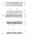
図1は、転写シートAの一実施態様を示す断面図である。図1において、1は基材シート、2は白金含有触媒層(撥水性の白金含有触媒層)である。 FIG. 1 is a cross-sectional view showing an embodiment of the transfer sheet A. In FIG. 1, 1 is a base material sheet, 2 is a platinum containing catalyst layer (water-repellent platinum containing catalyst layer).
図2は、転写シートBの一実施態様を示す平面図であり、図3は該転写シートBのA−A線断面図である。図4は、転写シートBの他の一実施態様を示す断面図である。図2、図3及び図4において、1は基材シート、2は白金含有触媒層、3は親水性領域、4は撥水性領域である。 FIG. 2 is a plan view showing an embodiment of the transfer sheet B, and FIG. 3 is a cross-sectional view of the transfer sheet B along the line AA. FIG. 4 is a cross-sectional view showing another embodiment of the transfer sheet B. 2, 3 and 4, 1 is a base material sheet, 2 is a platinum-containing catalyst layer, 3 is a hydrophilic region, and 4 is a water-repellent region.
図3に示される転写シートBにおいて、親水性領域3は、基材シート1と反対側の白金含有触媒層の表層部に形成されている。図4に示される転写シートBにおいて、親水性領域3は、基材シート1と反対側の白金含有触媒層の表層部から、基材シート1と接する側の白金含有触媒層の表層部までの全体に亘って形成されている。
In the transfer sheet B shown in FIG. 3, the
親水性領域と撥水性領域とを有する白金含有触媒層の形成方法について、図面を引用しつつ説明する。 A method for forming a platinum-containing catalyst layer having a hydrophilic region and a water-repellent region will be described with reference to the drawings.
図5は、本発明の親水性領域と撥水性領域とを有する白金含有触媒層の形成方法について概略を示す図面である。 FIG. 5 is a drawing schematically showing a method for forming a platinum-containing catalyst layer having a hydrophilic region and a water-repellent region according to the present invention.
図5(a)中のAは、基材シート1の一方面全体に撥水性の白金含有触媒層2が形成された本発明転写シートであり、Cは、基材5の一方面全体に光触媒層6が形成された積層体である。
A in FIG. 5A is the transfer sheet of the present invention in which the water-repellent platinum-containing
転写シートAの撥水性の白金含有触媒層側と積層体Cの光触媒層とが対面するように、転写シートAと積層体Cとを配置し、積層体Cの反対側から、フォトマスク7を介して転写シートAに向かって光照射する(図5(b))。
The transfer sheet A and the laminate C are arranged so that the water-repellent platinum-containing catalyst layer side of the transfer sheet A and the photocatalyst layer of the laminate C face each other, and the
撥水性の白金含有触媒層に、光触媒含有層を介してエネルギー照射(光照射)すると、光触媒の作用により、光照射された白金含有触媒表面層の濡れ性が変化し、該白金含有触媒層の光照射部分に親水性領域が形成される(図5(c))。 When the water-repellent platinum-containing catalyst layer is irradiated with energy (light irradiation) through the photocatalyst-containing layer, the wettability of the light-irradiated platinum-containing catalyst surface layer is changed by the action of the photocatalyst, and the platinum-containing catalyst layer A hydrophilic region is formed in the light irradiated portion (FIG. 5C).
フォトマスク7は、図5において、光を透過する部分8と光を透過しない部分9とからなっているが、図6に示すように、光を透過する層8’の一方面の一部に光遮断層9’が形成されていてもよい。
In FIG. 5, the
フォトマスク7の基材としては、公知のものを広く使用できる。フォトマスクの基材としては、例えば、ステンレス板等の金属基板をエッチングして物理的に孔を形成したもの、アルミニウム等の金属箔を積層したフィルムを部分的に打ち抜いたもの、フィルムに部分的に金属蒸着や着色を施したもの等を挙げることができる。
As a base material of the
本発明の白金含有触媒層2は、このようにして親水性領域3と撥水性領域4とが形成されている。
In the platinum-containing
光照射時の光照射条件によっては、光照射された白金含有触媒層の表面層だけでなく、白金含有触媒層内部まで濡れ性が変化し、白金含有触媒層の表面層及び内部の全体に親水性領域が形成される(図4)。 Depending on the light irradiation conditions at the time of light irradiation, the wettability changes not only to the surface layer of the platinum-containing catalyst layer irradiated with light but also to the inside of the platinum-containing catalyst layer, and the surface layer of the platinum-containing catalyst layer and the whole inside are hydrophilic. Sex regions are formed (FIG. 4).
以上のように、白金含有触媒層に光触媒が含有されていない場合、白金含有触媒層の親水性領域は、白金含有触媒層に光触媒含有層を接触させ、光触媒含有層を通じて白金含有触媒層に光照射することにより形成される。 As described above, when the photocatalyst is not contained in the platinum-containing catalyst layer, the hydrophilic region of the platinum-containing catalyst layer is brought into contact with the platinum-containing catalyst layer, and light is transmitted to the platinum-containing catalyst layer through the photocatalyst-containing layer. It is formed by irradiation.
光触媒含有層
本発明に用いられる光触媒含有層は、光触媒含有層中の光触媒が、接触する白金含有触媒層の濡れ性を変化させるような構成であれば、特に限定されるものではない。光触媒含有層は、光触媒とバインダーとから構成されているものであってもよいし、光触媒のみで構成されていてもよい。また、光触媒含有層表面の濡れ性は、親水性及び撥水性のいずれであってもよい。
Photocatalyst-containing layer The photocatalyst-containing layer used in the present invention is not particularly limited as long as the photocatalyst in the photocatalyst-containing layer changes the wettability of the platinum-containing catalyst layer in contact therewith. The photocatalyst-containing layer may be composed of a photocatalyst and a binder, or may be composed of only a photocatalyst. Moreover, the wettability of the photocatalyst containing layer surface may be either hydrophilic or water repellent.
光触媒含有層に含まれる光触媒としては、光半導体として知られる光触媒を広く使用でき、例えば、二酸化チタン(TiO2)、酸化亜鉛(ZnO)、酸化スズ(SnO2)、チタン酸ストロンチウム(SrTiO3)、酸化タングステン(WO3)、酸化ビスマス(Bi2O3)、酸化鉄(Fe2O3)等を挙げることができる。これら光触媒は、1種単独で又は2種以上を混合して使用される。 As a photocatalyst contained in the photocatalyst-containing layer, a photocatalyst known as a photosemiconductor can be widely used. For example, titanium dioxide (TiO 2 ), zinc oxide (ZnO), tin oxide (SnO 2 ), strontium titanate (SrTiO 3 ) , Tungsten oxide (WO 3 ), bismuth oxide (Bi 2 O 3 ), iron oxide (Fe 2 O 3 ), and the like. These photocatalysts are used individually by 1 type or in mixture of 2 or more types.
本発明においては、バンドギャップエネルギーが高く、化学的に安定で毒性もなく、入手が容易な二酸化チタンを好適に使用できる。 In the present invention, titanium dioxide, which has a high band gap energy, is chemically stable, has no toxicity, and is easily available, can be suitably used.
二酸化チタンには、アナターゼ型とルチル型とがあり、本発明ではいずれのタイプでも使用することができる。アナターゼ型の二酸化チタンがより好ましい。アナターゼ型二酸化チタンは励起波長が380nm以下にある。 Titanium dioxide has an anatase type and a rutile type, and any type can be used in the present invention. Anatase type titanium dioxide is more preferred. Anatase type titanium dioxide has an excitation wavelength of 380 nm or less.
このようなアナターゼ型二酸化チタンとしては、より具体的には、塩酸解膠型のアナターゼ型チタニアゾル(石原産業(株)製のSTS−02(平均粒径7nm)、石原産業(株)製のST−K01)、硝酸解膠型のアナターゼ型チタニアゾル(日産化学(株)製のTA−15(平均粒径12nm))等を挙げることができる。
As such anatase type titanium dioxide, more specifically, hydrochloric acid peptizer type anatase type titania sol (STS-02 (average particle size: 7 nm) manufactured by Ishihara Sangyo Co., Ltd.), ST manufactured by Ishihara Sangyo Co., Ltd. -K01), anatase-type titania sol of nitrate peptization type (TA-15 (
光触媒の粒径が小さいほど光触媒反応が効率よく行われるので、粒径の比較的小さな光触媒を用いるのが好ましい。光触媒の平均粒径は、50nm以下が好ましく、20nm以下がより好ましい。ここで、平均粒径とは、全体の粒子径に対して累積50%に相当する粒子径をいう。 Since the photocatalytic reaction is performed more efficiently as the particle size of the photocatalyst is smaller, it is preferable to use a photocatalyst having a relatively small particle size. The average particle size of the photocatalyst is preferably 50 nm or less, and more preferably 20 nm or less. Here, the average particle diameter means a particle diameter corresponding to 50% of the total particle diameter.
光触媒含有層に含まれるバインダーとしては、バインダーの主骨格が上記光触媒の光励起により分解されないような高い結合エネルギーを有するものが好ましく、例えば、上記撥水性材料として用いられるオルガノポリシロキサンと同一のものを使用できる。 The binder contained in the photocatalyst-containing layer is preferably one having a high binding energy such that the main skeleton of the binder is not decomposed by photoexcitation of the photocatalyst. For example, the same one as the organopolysiloxane used as the water-repellent material is used. Can be used.
また、バインダーとして無定形シリカ前駆体を用いることができる。無定形シリカ前駆体としては、一般式 SiX4(Xは前記に同じ)で表される珪素化合物、又はそれらの加水分解物であるシラノール、或いは、平均分子量3000以下のポリシロキサン等を好ましく例示できる。 Moreover, an amorphous silica precursor can be used as a binder. Preferred examples of the amorphous silica precursor include a silicon compound represented by the general formula SiX 4 (X is the same as above), silanol which is a hydrolyzate thereof, or polysiloxane having an average molecular weight of 3000 or less. .
一般式 SiX4 で表される珪素化合物の具体例としては、テトラメトキシシラン、テトラエトキシシラン、テトライソプロポキシシラン、テトラ−n−プロポキシシラン、テトラ−n−ブトキシシラン等が挙げられる。 Specific examples of the silicon compound represented by the general formula SiX 4 include tetramethoxysilane, tetraethoxysilane, tetraisopropoxysilane, tetra-n-propoxysilane, tetra-n-butoxysilane and the like.
バインダーを用いた場合の光触媒含有層中の光触媒の含有量は、通常5〜60重量%、好ましくは20〜40重量%の範囲である。 When the binder is used, the content of the photocatalyst in the photocatalyst-containing layer is usually 5 to 60% by weight, preferably 20 to 40% by weight.
光触媒のみからなる光触媒含有層の形成方法としては、例えば、光触媒が二酸化チタンの場合は、基材(例えば、石英ガラス、フォトマスク基板等)上に無定形チタニアを形成し、次いで焼成により結晶性チタニアに相変化させる方法等が挙げられる。無定形チタニアは、例えば四塩化チタン、硫酸チタン等のチタンの無機塩を加水分解及び脱水縮合するか、テトラメトキシチタン、テトラエトキシチタン、テトライソプロポキシチタン、テトラ−n−プロポキシチタン、テトラ−n−ブトキシチタン等の有機チタン化合物を酸存在下において加水分解及び脱水縮合することにより、製造される。この無定形チタニアは、次いで、400℃〜500℃における焼成によってアナターゼ型チタニアに、また、600℃〜700℃の焼成によってルチル型チタニアに変化する。 As a method for forming a photocatalyst-containing layer composed only of a photocatalyst, for example, when the photocatalyst is titanium dioxide, amorphous titania is formed on a base material (for example, quartz glass, photomask substrate, etc.), and then crystallized by firing. For example, a method of changing the phase to titania. Amorphous titania is obtained by, for example, hydrolyzing and dehydrating and condensing an inorganic salt of titanium such as titanium tetrachloride, titanium sulfate, tetramethoxy titanium, tetraethoxy titanium, tetraisopropoxy titanium, tetra-n-propoxy titanium, tetra-n. -Manufactured by hydrolysis and dehydration condensation of an organic titanium compound such as butoxytitanium in the presence of an acid. This amorphous titania then changes to anatase titania by baking at 400 ° C. to 500 ° C. and to rutile type titania by baking at 600 ° C. to 700 ° C.
また、光触媒のみからなる光触媒含有層は、例えば、スパッタリング法、CVD法、真空蒸着法等の真空製膜法を用いことにより形成することができる。真空製膜法により光触媒含有層を形成することにより、均一な膜で且つ光触媒のみを含有する光触媒含有層とすることが可能であり、これにより撥水性材料層上の濡れ性を均一に変化させることが可能であり、更に光触媒含有層が光触媒のみからなることから、バインダーを用いる場合と比較して撥水性材料層上の濡れ性を効率的に変化させることが可能となる。 Moreover, the photocatalyst containing layer consisting of only the photocatalyst can be formed by using a vacuum film forming method such as a sputtering method, a CVD method, or a vacuum vapor deposition method. By forming the photocatalyst-containing layer by a vacuum film forming method, it is possible to obtain a photocatalyst-containing layer that is a uniform film and contains only the photocatalyst, thereby uniformly changing the wettability on the water-repellent material layer. In addition, since the photocatalyst-containing layer is composed only of the photocatalyst, the wettability on the water-repellent material layer can be changed efficiently as compared with the case of using a binder.
光触媒及びバインダーとしてオルガノポリシロキサンを含む光触媒含有層は、光触媒及びバインダーを必要に応じて他の添加剤と共に適当な溶剤中に分散して塗布液を調製し、この塗布液を基材上に塗布することにより形成することができる。使用される溶剤としては、例えば、エタノール、イソプロパノール等のアルコール系の有機溶剤が好ましい。塗布は、スピンコート、スプレーコート、ディッブコート、ロールコート、ビードコート等の公知の塗布方法により行うことができる。 A photocatalyst-containing layer containing organopolysiloxane as a photocatalyst and a binder is prepared by dispersing the photocatalyst and binder in an appropriate solvent together with other additives as necessary, and applying this coating liquid on a substrate. Can be formed. As the solvent used, for example, alcohol-based organic solvents such as ethanol and isopropanol are preferable. The coating can be performed by a known coating method such as spin coating, spray coating, dip coating, roll coating or bead coating.
また、バインダ−として紫外線硬化型の成分を含有している場合、光触媒及びバインダーを必要に応じて他の添加剤と共に適当な溶剤中に分散して塗布液を調製し、この塗布液を基材上に塗布後、これに紫外線を照射して硬化処理を行うことにより光触媒含有層を形成することかできる。 Further, when an ultraviolet curable component is contained as a binder, a photocatalyst and a binder are dispersed in an appropriate solvent together with other additives as necessary to prepare a coating solution, and this coating solution is used as a base material. A photocatalyst containing layer can be formed by irradiating this with ultraviolet rays and applying a curing treatment after coating.
光触媒及びバインダーとして無定形シリカ前駆体を含む光触媒含有層は、光触媒の粒子と無定形シリカ前駆体とを非水性溶媒中に均一に分散させ、基材上に空気中の水分により加水分解させてシラノールを形成させた後、常温で脱水縮重合することにより光触媒含有層を形成できる。シラノールの脱水縮重合を100℃以上で行えば、シラノールの重合度を大きくでき、光触媒含有層の膜表面の強度を向上できる。 The photocatalyst-containing layer containing an amorphous silica precursor as a photocatalyst and a binder is obtained by uniformly dispersing photocatalyst particles and amorphous silica precursor in a non-aqueous solvent and hydrolyzing the substrate with moisture in the air. After the silanol is formed, the photocatalyst-containing layer can be formed by dehydration condensation polymerization at room temperature. If dehydration condensation polymerization of silanol is performed at 100 ° C. or higher, the degree of polymerization of silanol can be increased, and the strength of the film surface of the photocatalyst-containing layer can be improved.
光触媒含有層に含まれるバインダーとしては、上記で述べたバインダーを1種又は2種以上混合して使用できる。 As a binder contained in a photocatalyst content layer, the above-mentioned binder can be used 1 type or in mixture of 2 or more types.
光触媒含有層には、上記光触媒、バインダーの他に、界面活性剤を含有させることができる。界面活性剤としては、具体的には、日光ケミカルズ(株)製のNIKKOL BL、BC、BO、BBの各シリーズ等の炭化水素系の非イオン界面活性剤、デュポン社製のZONYL FSN、FSO、旭硝子(株)製サーフロンS−141、145、大日本インキ化学工業(株)製のメガファックF−141、144、ネオス(株)製のフタージェントF−200、F251、ダイキン工業(株)製のユニダインDS−401、402、スリーエム(株)製のフロラードFC−170、176等のフッ素系又はシリコーン系の非イオン界面活性剤等を挙げることかできる。また、非イオン界面活性剤の代わりに、カチオン系界面活性剤、アニオン系界面活性剤、両性界面活性剤を用いることもできる。 In addition to the photocatalyst and the binder, the photocatalyst-containing layer can contain a surfactant. Specific examples of the surfactant include hydrocarbon non-ionic surfactants such as NIKKOL BL, BC, BO, and BB series manufactured by Nikko Chemicals, ZONYL FSN, FSO, manufactured by DuPont, and the like. Asahi Glass Co., Ltd. Surflon S-141, 145, Dainippon Ink & Chemicals Co., Ltd. MegaFuck F-141, 144, Neos Co., Ltd. Footgent F-200, F251, Daikin Industries, Ltd. Fluorine-based or silicone-based nonionic surfactants such as Unidyne DS-401, 402 and Fluorard FC-170, 176 manufactured by 3M Co., Ltd. can be used. Moreover, a cationic surfactant, an anionic surfactant, and an amphoteric surfactant can also be used instead of a nonionic surfactant.
光触媒含有層には、上記の界面活性剤の他にも、ポリビニルアルコール、不飽和ポリエステル、アクリル樹脂、ポリエチレン、ジアリルフタレート、エチレンプロピレンジエンモノマー、エポキシ樹脂、フェノール樹脂、ポリウレタン、メラミン樹脂、ポリカーボネート、ポリ塩化ビニル、ポリアミド、ポリイミド、スチレンブタジエンゴム、クロロプレンゴム、ポリプロピレン、ポリブチレン、ポリスチレン、ポリ酢酸ビニル、ポリエステル、ポリブタジエン、ポリベンゾイミダゾール、ポリアクリルニトリル、ポリサルファイド、ポリイソプレン等のオリゴマーないしポリマー等を含有させることができる。 In addition to the above surfactants, the photocatalyst-containing layer includes polyvinyl alcohol, unsaturated polyester, acrylic resin, polyethylene, diallyl phthalate, ethylene propylene diene monomer, epoxy resin, phenol resin, polyurethane, melamine resin, polycarbonate, poly Containing oligomers or polymers such as vinyl chloride, polyamide, polyimide, styrene butadiene rubber, chloroprene rubber, polypropylene, polybutylene, polystyrene, polyvinyl acetate, polyester, polybutadiene, polybenzimidazole, polyacrylonitrile, polysulfide, polyisoprene, etc. Can do.
光触媒含有層が光触媒のみからなる場合は、白金含有触媒層上の濡れ性の変化効率が向上し、処理時間の短縮化等のコスト面で有利である。一方、光触媒含有層が光触媒及びバインダーを含有している場合は、光触媒含有層の形成が容易であるという利点を有する。 When the photocatalyst-containing layer is composed only of the photocatalyst, the wettability change efficiency on the platinum-containing catalyst layer is improved, which is advantageous in terms of cost such as shortening of the processing time. On the other hand, when the photocatalyst-containing layer contains a photocatalyst and a binder, the photocatalyst-containing layer can be easily formed.
光触媒含有層6は、基材5上の全面に形成されていてもよいし(図5(a))、基材1上の全面ではなく、基材5上の一部にパターン状に形成されていてもよい(図7)。
The photocatalyst-containing
この光触媒含有層のパターニング方法は、特に限定されるものではないが、例えばフォトリソグラフィー法等により行うことが可能である。 The method for patterning the photocatalyst-containing layer is not particularly limited, but can be performed by, for example, a photolithography method.
本発明では、光触媒含有層が形成される基材としてフォトマスク基材を用いてもよい。光触媒含有層が形成されたフォトマスク基材を用いると、本発明ガス拡散電極の製造工程を簡略化でき、有利である。この際に使用されるフォトマスク基材は、通常、フィルムに部分的に金属蒸着を施したものである。 In the present invention, a photomask substrate may be used as the substrate on which the photocatalyst-containing layer is formed. Use of a photomask base material on which a photocatalyst-containing layer is formed is advantageous because it can simplify the production process of the gas diffusion electrode of the present invention. The photomask substrate used at this time is usually a film obtained by partial metal deposition.
斯かるフォトマスク基材の一方面に光触媒層を形成させた積層体を、後述するように該積層体の光触媒層側を白金含有触媒層と接触させ、フォトマスク基材側からエネルギー(光)を照射すると、撥水性の白金含有触媒層を簡易に親水性領域及び撥水性領域を有する白金含有触媒層に変換することができる。 The laminated body in which the photocatalyst layer is formed on one surface of such a photomask base is brought into contact with the platinum-containing catalyst layer on the photocatalyst layer side of the laminated body as described later, and energy (light) is transmitted from the photomask base. , The water-repellent platinum-containing catalyst layer can be easily converted into a platinum-containing catalyst layer having a hydrophilic region and a water-repellent region.
光触媒含有層6が基材5上の一部にパターン状に形成されている場合には、積層体Cの基材側から基材全面に亘って光照射しても、光触媒含有層6と接する撥水性の白金含有触媒層2の部分だけ親水性領域に変換されるので、フォトマスクを使用しなくてもよい(図8)。
In the case where the photocatalyst-containing
光触媒含有層と撥水性材料層との接触
白金含有触媒層2に光触媒含有層6を接触させ、光触媒含有層側からエネルギー(光)を照射すると、白金含有触媒層の光触媒含有層と接触している部分の化学的性質が撥水性から親水性に変化する。
Contact between the photocatalyst containing layer and the water repellent material layer When the
光触媒含有層における光触媒の作用機構については、未だ解明されていないが、光の照射によって生成したキャリアが、近傍の化合物との直接反応、又は、酸素及び水の存在下で生じた活性酸素種によって、有機物の化学構造に変化を及ぼすものと考えられる。本発明においては、このキャリアが光触媒含有層と接触している白金含有触媒層中の化合物になんらかの作用をするものと推察される。 The mechanism of action of the photocatalyst in the photocatalyst-containing layer has not yet been elucidated, but the carriers generated by light irradiation may react directly with nearby compounds or by reactive oxygen species generated in the presence of oxygen and water. It is thought that it changes the chemical structure of organic matter. In the present invention, this carrier is presumed to have some action on the compound in the platinum-containing catalyst layer in contact with the photocatalyst-containing layer.
本発明においては、エネルギー照射時に光触媒含有層と撥水性の白金含有触媒層とが接触するように配置することが重要である。 In the present invention, it is important to dispose the photocatalyst containing layer and the water repellent platinum containing catalyst layer in contact with each other during energy irradiation.
本発明において、接触とは、実質的に光触媒の作用が撥水性の白金含有触媒層表面に及ぶような状態で配置された状態をいうこととし、実際に物理的に接触している状態の他、所定の間隔を隔てて光触媒含有層と撥水性の白金含有触媒層とが配置された状態をも含む概念とする。 In the present invention, the contact means a state where the action of the photocatalyst substantially extends to the surface of the water-repellent platinum-containing catalyst layer. The concept includes a state in which the photocatalyst-containing layer and the water-repellent platinum-containing catalyst layer are arranged at a predetermined interval.
ここで、上記所定の間隔としては、具体的には、通常0.2μm〜10μm、好ましくは1μm〜5μmの範囲内である。 Here, specifically, the predetermined interval is usually 0.2 μm to 10 μm, preferably 1 μm to 5 μm.
光触媒含有層と白金含有触媒層表面とを所定の間隔で離して配置することにより、酸素、水及び光触媒作用により生じた活性酸素種が脱着し易くなるので、好ましい。上記範囲より光触媒含有層と白金含有触媒層との間隔を離して配置した場合は、生じた活性酸素種が濡れ性変化層に届き難くなり、濡れ性の変化速度が遅くなる場合がある。 By disposing the photocatalyst-containing layer and the platinum-containing catalyst layer surface at a predetermined interval, it is preferable because oxygen, water, and active oxygen species generated by the photocatalytic action are easily desorbed. When the photocatalyst-containing layer and the platinum-containing catalyst layer are spaced apart from the above range, the generated active oxygen species are difficult to reach the wettability changing layer, and the wettability change rate may be slow.
本発明においては、このような接触状態は、少なくとも露光の間だけ維持されていればよい。 In the present invention, such a contact state only needs to be maintained at least during exposure.
極めて狭い間隙を均一に形成して光触媒含有層と撥水性の白金含有触媒層とを配置する方法としては、例えばスペーサを用いる方法を挙げることができる。スペーサを用いることにより、均一な間隙を形成することができると共に、スペーサが接触する部分は、光触媒の作用が白金含有触媒層表面に及ばないことから、スペーサを所望する親水性領域のパターンと同一のパターン形状とすることにより、白金含有触媒層上に所定の親水性領域パターンを形成することができる。 As a method for forming a very narrow gap uniformly and arranging the photocatalyst-containing layer and the water-repellent platinum-containing catalyst layer, for example, a method using a spacer can be mentioned. By using the spacer, a uniform gap can be formed, and the portion where the spacer contacts is the same as the pattern of the hydrophilic region where the spacer is desired because the photocatalytic action does not reach the surface of the platinum-containing catalyst layer. By adopting this pattern shape, a predetermined hydrophilic region pattern can be formed on the platinum-containing catalyst layer.
本発明においては、このようなスペーサを一つの部材として形成してもよいが、白金含有触媒層上に親水性領域を簡易に形成させる観点から、基材上に形成された光触媒含有層の表面にスペーサを形成することが好ましい。 In the present invention, such a spacer may be formed as one member, but from the viewpoint of easily forming a hydrophilic region on the platinum-containing catalyst layer, the surface of the photocatalyst-containing layer formed on the substrate. Preferably, a spacer is formed on the substrate.
スペーサは、光触媒の作用が及ばないように白金含有触媒層表面を保護する作用を有していれば足りるので、照射されるエネルギーを遮蔽する機能を有していない材料から構成されていてもよい。 Since the spacer only needs to have an action of protecting the surface of the platinum-containing catalyst layer so that the action of the photocatalyst does not reach, the spacer may be made of a material that does not have a function of shielding the irradiated energy. .
接触部分へのエネルギー照射
撥水性の白金含有触媒層と光触媒含有層とが接触している状態で、光触媒含有層側からエネルギー照射が行われる。
Energy irradiation to the contact portion Energy irradiation is performed from the photocatalyst containing layer side in a state where the water-repellent platinum-containing catalyst layer and the photocatalyst containing layer are in contact.
本発明でいうエネルギー照射(露光)とは、光触媒含有層による撥水性の白金含有触媒層表面の濡れ性を変化させることが可能ないかなるエネルギー線の照射をも含む概念であり、可視光の照射に限定されるものではない。 The energy irradiation (exposure) in the present invention is a concept including irradiation of any energy beam capable of changing the wettability of the surface of the water-repellent platinum-containing catalyst layer by the photocatalyst-containing layer. It is not limited to.
通常このような露光に用いる光の波長は、400nm以下の範囲、好ましくは380nm以下の範囲から適宜設定されるが、これに限定されるものではない。 Usually, the wavelength of light used for such exposure is appropriately set within a range of 400 nm or less, preferably 380 nm or less, but is not limited thereto.
このようなエネルギー線としては、例えば、紫外線、可視光線、赤外線の他、これらの光線よりも更に短波長又は長波長の電磁波、放射線等が挙げられる。例えば、光触媒として、アナターゼ型チタニアを用いる場合は、励起波長が380nm以下にあるので、光触媒の励起は紫外線により行うことができる。 Examples of such energy rays include ultraviolet rays, visible rays, infrared rays, electromagnetic waves having shorter wavelengths or longer wavelengths than these rays, and radiation. For example, when anatase titania is used as the photocatalyst, the excitation wavelength is 380 nm or less, so that the photocatalyst can be excited by ultraviolet rays.
露光に使用される光源としては、公知のものを広く使用でき、例えば、水銀ランプ、メタルハライドランプ、キセノンランプ、エキシマランプ、その他種々の光源を挙げることができる。 As a light source used for exposure, a well-known thing can be used widely, For example, a mercury lamp, a metal halide lamp, a xenon lamp, an excimer lamp, and other various light sources can be mentioned.
露光に際してのエネルギーの照射量は、撥水性の白金含有触媒層表面が光触媒の作用により撥水性の白金含有触媒層表面の濡れ性の変化が行われるのに十分な照射量とする。 The irradiation amount of energy at the time of exposure is set so that the wettability of the surface of the water-repellent platinum-containing catalyst layer is changed by the action of the photocatalyst.
この際、光触媒を加熱しながら露光することにより、光触媒の感度を上昇させことが可能となり、効率的な濡れ性の変化を行うことができる点で好ましい。具体的には30℃〜80℃の範囲内で加熱することが好ましい。 In this case, the photocatalyst is exposed to light while being heated, so that the sensitivity of the photocatalyst can be increased, and the wettability can be changed efficiently. Specifically, it is preferable to heat within a range of 30 ° C to 80 ° C.
使用される光触媒層が、図7に示すように基材上の一部にパターン状に形成されている場合には、これを図8に示すように白金含有触媒層2の面上に配置し、エネルギーを光触媒層を含む基材全面に亘って照射すればよい。
When the photocatalyst layer used is formed in a pattern on a part of the substrate as shown in FIG. 7, it is arranged on the surface of the platinum-containing
使用される光触媒層が、図5に示すように基材上の全面に形成されている場合には、所望の形状を有するフォトマスクを介して、エネルギーを光触媒層に照射すればよい。或いは、フォトマスクを使用することなく、エキシマ、YAG等のレーザーを用いてパターン状に描画照射することも可能である。また、その際に、必要に応じて上述した所望の形状を有するスペーサを用いてもよい。 In the case where the photocatalyst layer to be used is formed on the entire surface of the substrate as shown in FIG. 5, the photocatalyst layer may be irradiated with energy through a photomask having a desired shape. Alternatively, it is also possible to irradiate with a pattern using a laser such as an excimer or YAG without using a photomask. At that time, a spacer having the desired shape described above may be used as necessary.
エネルギーの照射方向は、上記光触媒含有層と撥水性の白金含有触媒層とが接触する部分にエネルギーが照射されるものであれば、いかなる方向から照射されてもよく、また、照射されるエネルギーも特に平行光等の平行なものに限定されない。 The direction of energy irradiation may be from any direction as long as energy is irradiated to the portion where the photocatalyst-containing layer and the water-repellent platinum-containing catalyst layer are in contact with each other. In particular, it is not limited to parallel things such as parallel light.
撥水性の白金含有触媒層に、光触媒含有層を介して光照射すると、光触媒の作用により、光照射された撥水性の白金含有触媒層表面の濡れ性が変化し、該白金含有触媒層の光照射部分に親水性領域が形成される。このようにして、親水性領域と撥水性領域とを有する白金含有触媒層が製造される。 When the water-repellent platinum-containing catalyst layer is irradiated with light through the photocatalyst-containing layer, the wettability of the surface of the water-repellent platinum-containing catalyst layer irradiated with the light is changed by the action of the photocatalyst, and the light of the platinum-containing catalyst layer is changed. A hydrophilic region is formed in the irradiated portion. In this way, a platinum-containing catalyst layer having a hydrophilic region and a water repellent region is produced.
本発明の白金含有触媒層には、複数個の親水性領域が撥水性領域を挟んで一定間隔で存在しているのが好ましい。 In the platinum-containing catalyst layer of the present invention, it is preferable that a plurality of hydrophilic regions exist at regular intervals with the water-repellent region interposed therebetween.
白金含有触媒層に光触媒が含有されていない場合、本発明の転写シートBは、例えば、
(i)基材シートの一方面上に(a)白金又は白金化合物触媒を担持した炭素粒子、(b)水素イオン伝導性高分子物質及び(c)エネルギー照射により水に対する濡れ性が撥水性から親水性に変化する物質を含有する白金含有触媒層を形成する工程、及び
(ii)白金含有触媒層に光触媒含有層を接触させ、光触媒含有層を通じて白金含有触媒層にエネルギーを照射する工程
を経て、製造される。
When the platinum-containing catalyst layer does not contain a photocatalyst, the transfer sheet B of the present invention is, for example,
(i) (a) carbon particles carrying platinum or a platinum compound catalyst on one side of the base sheet, (b) hydrogen ion conductive polymer substance, and (c) water wettability due to energy irradiation due to water repellency Forming a platinum-containing catalyst layer containing a substance that changes to hydrophilicity; and
(ii) The photocatalyst containing layer is brought into contact with the platinum containing catalyst layer, and the platinum containing catalyst layer is irradiated with energy through the photocatalyst containing layer.
白金含有触媒層に光触媒が含有されている場合
白金含有触媒層に含有される光触媒としては、上記で述べた光触媒をいずれも使用することができる。光触媒の含有量は、特に限定されるものではなく、広い範囲内から適宜選択できる。例えば、白金含有触媒層中の(c)成分である濡れ性変化物質1モルに対して、通常0.01〜4モル程度、好ましくは0.05〜2モル程度、より好ましくは0.1〜1モル程度の光触媒が含有される。
When the platinum-containing catalyst layer contains a photocatalyst As the photocatalyst contained in the platinum-containing catalyst layer, any of the photocatalysts described above can be used. The content of the photocatalyst is not particularly limited and can be appropriately selected from a wide range. For example, with respect to 1 mol of the wettability variable substance that is the component (c) in the platinum-containing catalyst layer, it is usually about 0.01 to 4 mol, preferably about 0.05 to 2 mol, more preferably 0.1 to About 1 mol of photocatalyst is contained.
白金含有触媒層に光触媒が含有されている場合、フォトマスクを介して白金含有触媒層にエネルギー(光)を照射すると、撥水性の白金含有触媒層を簡易に親水性領域及び撥水性領域を有する白金含有触媒層に変換することができる。 When the platinum-containing catalyst layer contains a photocatalyst, when the platinum-containing catalyst layer is irradiated with energy (light) through a photomask, the water-repellent platinum-containing catalyst layer easily has a hydrophilic region and a water-repellent region. It can be converted into a platinum-containing catalyst layer.
所望の形状を有するフォトマスクを使用すると、それに対応した形状の親水性領域を白金含有触媒層に形成させることができる。或いは、フォトマスクを使用することなく、エキシマ、YAG等のレーザーを用いてパターン状に描画照射することも可能である。また、その際に、必要に応じて上述した所望の形状を有するスペーサを用いてもよい。 When a photomask having a desired shape is used, a hydrophilic region having a shape corresponding to the photomask can be formed on the platinum-containing catalyst layer. Alternatively, it is also possible to irradiate with a pattern using a laser such as an excimer or YAG without using a photomask. At that time, a spacer having the desired shape described above may be used as necessary.
エネルギー照射の条件は、上記と同様でよい。 The conditions for energy irradiation may be the same as described above.
白金含有触媒層に光触媒が含有されている場合、本発明の転写シートBは、例えば、
(i)基材シートの一方面上に(a)白金又は白金化合物触媒を担持した炭素粒子、(b)水素イオン伝導性高分子物質、(c)エネルギー照射により水に対する濡れ性が撥水性から親水性に変化する物質及び(d)光触媒を含有する白金含有触媒層を形成する工程、及び
(ii)白金含有触媒層にエネルギーを照射する工程
を経て、製造される。
When the platinum-containing catalyst layer contains a photocatalyst, the transfer sheet B of the present invention is, for example,
(i) (a) carbon particles carrying platinum or a platinum compound catalyst on one side of the substrate sheet, (b) hydrogen ion conductive polymer material, (c) water wettability due to energy irradiation due to water repellency Forming a platinum-containing catalyst layer containing a substance that changes to hydrophilicity and (d) a photocatalyst; and
(ii) It is manufactured through a step of irradiating the platinum-containing catalyst layer with energy.
触媒層付き固体電解質膜
本発明の触媒層付き固体電解質膜(触媒層−電解質膜積層体)は、例えば、本発明転写シートBの触媒層面が電解質膜面に対面するように転写シートBを配置し、加圧した後、該転写シートの基材を剥離することにより製造される。この操作を2回繰り返すことにより、触媒層面が電解質膜の両面に積層された触媒層−電解質膜積層体が製造される。
Solid electrolyte membrane with catalyst layer The solid electrolyte membrane with catalyst layer (catalyst layer-electrolyte membrane laminate) of the present invention has, for example, the transfer sheet B disposed so that the catalyst layer surface of the transfer sheet B of the present invention faces the electrolyte membrane surface And after pressurizing, the substrate of the transfer sheet is peeled off. By repeating this operation twice, a catalyst layer-electrolyte membrane laminate in which the catalyst layer surface is laminated on both surfaces of the electrolyte membrane is produced.
作業性を考慮すると、触媒層面を電解質膜の両面に同時に積層するのがよい。この場合には、例えば、本発明転写シートBの触媒層面が電解質膜の両面に対面するように転写シートBを配置し、加圧した後、該転写シートの基材を剥離すればよい。 In consideration of workability, the catalyst layer surface is preferably laminated on both surfaces of the electrolyte membrane at the same time. In this case, for example, the transfer sheet B may be disposed such that the catalyst layer surface of the transfer sheet B of the present invention faces both surfaces of the electrolyte membrane, and after pressing, the substrate of the transfer sheet may be peeled off.
使用される電解質膜は、公知のものである。電解質膜の膜厚は、通常20〜250μm程度、好ましくは20〜80μm程度である。電解質膜の具体例としては、デュポン社製の「Nafion」膜、旭硝子(株)製の「Flemion」膜、旭化成(株)製の「Aciplex」膜、ゴア(Gore)社製の「Gore Select」膜等が挙げられる。 The electrolyte membrane used is a known one. The thickness of the electrolyte membrane is usually about 20 to 250 μm, preferably about 20 to 80 μm. Specific examples of electrolyte membranes include DuPont's “Nafion” membrane, Asahi Glass's “Flemion” membrane, Asahi Kasei's “Aciplex” membrane, and Gore's “Gore Select” Examples include membranes.
加圧レベルは、転写不良を避けるために、通常0.5〜20Mpa程度、好ましくは1〜10Mpa程度がよい。また、この加圧操作の際に、転写不良を避けるために、加圧面を加熱するのが好ましい。加熱温度は、電解質膜の破損、変性等を避けるために、通常200℃以下、好ましくは150℃以下がよい。 The pressure level is usually about 0.5 to 20 Mpa, preferably about 1 to 10 Mpa in order to avoid transfer failure. Further, it is preferable to heat the pressure surface during this pressure operation in order to avoid transfer failure. The heating temperature is usually 200 ° C. or lower, preferably 150 ° C. or lower, in order to avoid breakage, modification and the like of the electrolyte membrane.
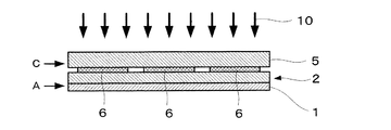
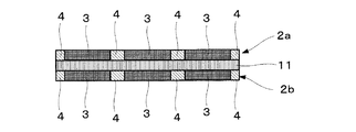
本発明の触媒層−電解質膜積層体の一例を図9に示す。また、本発明の触媒層−電解質膜積層体の他の一例を図10に示す。 An example of the catalyst layer-electrolyte membrane laminate of the present invention is shown in FIG. Another example of the catalyst layer-electrolyte membrane laminate of the present invention is shown in FIG.
本発明転写シートAを構成する白金含有触媒層に光触媒が含まれている場合、まず、転写シートAを用いて触媒層付き固体電解質膜を製造し、次いで所望形状のフォトマスク等を用いて触媒層付き固体電解質膜の両面をエネルギー照射することによっても、本発明の触媒層付き固体電解質膜を製造することができる。 When the platinum-containing catalyst layer constituting the transfer sheet A of the present invention contains a photocatalyst, first, a solid electrolyte membrane with a catalyst layer is produced using the transfer sheet A, and then the catalyst is produced using a photomask having a desired shape. The solid electrolyte membrane with a catalyst layer of the present invention can also be produced by irradiating energy on both sides of the solid electrolyte membrane with a layer.
電極−電解質膜接合体
本発明の電極−電解質膜接合体は、触媒層−電解質膜積層体の両面に電極基材を配置し、加圧することにより製造される。
Electrode-electrolyte membrane assembly The electrode-electrolyte membrane assembly of the present invention is produced by placing electrode substrates on both sides of a catalyst layer-electrolyte membrane laminate and applying pressure.
電極基材は、公知であり、燃料極、空気極を構成する各種の電極基材を使用できる。 The electrode base material is well known, and various electrode base materials constituting a fuel electrode and an air electrode can be used.
加圧レベルは、通常0.1〜100Mpa程度、好ましくは5〜15Mpa程度がよい。この加圧操作の際に加熱するのが好ましく、加熱温度は通常120〜150℃程度でよい。 The pressure level is usually about 0.1 to 100 Mpa, preferably about 5 to 15 Mpa. It is preferable to heat at the time of this pressurization operation, and heating temperature may be about 120-150 degreeC normally.
本発明の電極−電解質膜接合体の一例を図11に示す。 An example of the electrode-electrolyte membrane assembly of the present invention is shown in FIG.
燃料電池
本発明の燃料電池は、例えば、次のようにして製造される。
Fuel Cell The fuel cell of the present invention is manufactured, for example, as follows.
例えば、本発明の燃料電池は、
(1)本発明の転写シートBの触媒層面が固体電解質膜の片面又は両面に対面するように転写シートBを配置し、加圧した後、該転写シートBの基材を触媒層面から剥離することにより触媒層−電解質膜積層体を得る工程、
(2)上記(1)工程で得られる触媒層−電解質膜積層体の両面に電極基材を配置し、加圧することにより電極−電解質膜接合体を得る工程、及び
(3)上記(2)工程で得られる電極−電解質膜接合体を用いて燃料電池を得る工程
を経て製造される。
For example, the fuel cell of the present invention is
(1) The transfer sheet B is arranged so that the catalyst layer surface of the transfer sheet B of the present invention faces one or both surfaces of the solid electrolyte membrane, and after pressing, the substrate of the transfer sheet B is peeled off from the catalyst layer surface. A step of obtaining a catalyst layer-electrolyte membrane laminate by
(2) A step of obtaining an electrode-electrolyte membrane assembly by placing an electrode substrate on both sides of the catalyst layer-electrolyte membrane laminate obtained in the step (1) and applying pressure; and
(3) Manufactured through a step of obtaining a fuel cell using the electrode-electrolyte membrane assembly obtained in the step (2).
本発明は、上記電極−電解質膜接合体を組み込んだ燃料電池を提供する。 The present invention provides a fuel cell incorporating the electrode-electrolyte membrane assembly.
本発明によれば、優れた親水性及び撥水性を兼備する触媒層付き固体電解質膜を製造するための、触媒層転写シートを提供できる。 According to the present invention, a catalyst layer transfer sheet for producing a solid electrolyte membrane with a catalyst layer having both excellent hydrophilicity and water repellency can be provided.
本発明の触媒層転写シートを用いることにより、優れた親水性及び撥水性を兼備する触媒層付き固体電解質膜並びに優れた親水性及び撥水性を兼備する電極−電解質膜接合体を容易に製造することができる。 By using the catalyst layer transfer sheet of the present invention, a solid electrolyte membrane with a catalyst layer having both excellent hydrophilicity and water repellency and an electrode-electrolyte membrane assembly having both excellent hydrophilicity and water repellency are easily produced. be able to.
本発明の触媒層転写シートから製造される電極−電解質膜接合体は、優れた親水性及び撥水性を兼備し、該接合体から、所望の性能を取り出すことのできる燃料電池を製造することができる。 The electrode-electrolyte membrane assembly produced from the catalyst layer transfer sheet of the present invention has excellent hydrophilicity and water repellency, and can produce a fuel cell from which desired performance can be taken out. it can.
以下に実施例を掲げて、本発明を一層明らかにする。 The present invention will be further clarified by the following examples.
実施例1
1.濡れ性変化物質含有ペースト組成物の調製
フルオロメチルシラン(GE東芝シリコーン(株)製のTSL8233)0.4g、テトラメトキシシラン(GE東芝シリコーン(株)製のTSL8114)5g及び0.05規定塩酸2.5gを混合し、8時間攪拌した。得られた溶液をイソプロピルアルコールを用いて10倍に希釈し、濡れ性変化物質含有ペースト組成物とした。
Example 1
1. Preparation of a wettability-changing substance-containing paste composition 0.4 g of fluoromethylsilane (TSL8233 manufactured by GE Toshiba Silicone Co., Ltd.), 5 g of tetramethoxysilane (TSL8114 manufactured by GE Toshiba Silicone Co., Ltd.) and 0.05
2.白金含有触媒層の形成
カソード触媒層形成用インキ(ペースト)は、白金担持触媒(Pt:50wt%、田中貴金属工業製のTEC10E50E)10g、5wt%ナフィオン溶液(デュポン社製、溶剤プロパノール)50g、上記で調製した濡れ性変化物質含有ペースト組成物20g及びイソプロパノール(和光純薬(株)製)30gを分散機にて攪拌混合することにより調製した。
2. Formation of platinum-containing catalyst layer Cathode catalyst layer forming ink (paste) is a platinum-supported catalyst (Pt: 50 wt%, TEC10E50E manufactured by Tanaka Kikinzoku Kogyo), 10 g, a 5 wt% Nafion solution (manufactured by DuPont, solvent propanol), 50 g 20 g of the wettability changing substance-containing paste composition prepared in the above and 30 g of isopropanol (manufactured by Wako Pure Chemical Industries, Ltd.) were mixed by stirring with a disperser.
アノード触媒層形成用インキ(ペースト)は、白金−ルテニウム担持触媒(田中貴金属工業製のTEC66E50)10g、5wt%ナフィオン溶液(デュポン社製、溶剤プロパノール)50g、上記で調製した濡れ性変化物質含有ペースト組成物20g及びイソプロパノール(和光純薬(株)製)30gを分散機にて攪拌混合することにより調製した。 The anode catalyst layer forming ink (paste) was a platinum-ruthenium supported catalyst (TEC66E50 manufactured by Tanaka Kikinzoku Kogyo Co., Ltd.), 5 g Nafion solution (manufactured by DuPont, solvent propanol) 50 g, and the wettability variable substance-containing paste prepared above. 20 g of the composition and 30 g of isopropanol (manufactured by Wako Pure Chemical Industries, Ltd.) were prepared by stirring and mixing with a disperser.
ポリエチレンテレフタレートフィルム(東洋紡績製のE3120、厚さ12μm)の一方面上に、スクリーン印刷にて、カソード触媒層の乾燥後の厚さが20μmとなるようにカソード触媒層形成用インキ塗布し、100℃で10分間乾燥して、本発明のカソード触媒層転写シートAを製造した。 On one surface of a polyethylene terephthalate film (E3120 manufactured by Toyobo Co., Ltd., 12 μm thick), an ink for forming a cathode catalyst layer was applied by screen printing so that the thickness after drying of the cathode catalyst layer was 20 μm. The cathode catalyst layer transfer sheet A of the present invention was produced by drying at 10 ° C. for 10 minutes.
ポリエチレンテレフタレートフィルム(東洋紡績製のE3120、厚さ12μm)の一方面上に、スクリーン印刷にて、アノード触媒層の乾燥後の厚さが20μmとなるようにアノード触媒層形成用インキ塗布し、100℃で10分間乾燥して、本発明のアノード触媒層転写シートAを製造した。
On one surface of a polyethylene terephthalate film (E3120 manufactured by Toyobo Co., Ltd.,
3.光触媒含有層の作成
テトラメトキシシラン(GE東芝シリコーン(株)製のTSL8114)5g及び0.05規定塩酸2.5gを混合し、24時間攪拌した。得られた溶液0.1gに、光触媒無機コーティング剤(石原産業(株)製のST−K01)50gを混合し、1時間常温で撹拌した。次いでこの溶液をイソプロピルアルコールを用いて2倍に希釈し、光触媒含有層形成用組成物とした。
3. Preparation of photocatalyst containing layer 5 g of tetramethoxysilane (TSL8114 manufactured by GE Toshiba Silicone Co., Ltd.) and 2.5 g of 0.05 N hydrochloric acid were mixed and stirred for 24 hours. To 0.1 g of the obtained solution, 50 g of a photocatalytic inorganic coating agent (ST-K01 manufactured by Ishihara Sangyo Co., Ltd.) was mixed and stirred at room temperature for 1 hour. Subsequently, this solution was diluted 2 times with isopropyl alcohol to obtain a photocatalyst-containing layer forming composition.
次にフォトマスク基板(50×50mm)を用意した。このマスクは、開口率を80%とし、開口部のパターンは、パターン幅2.00mm、パターンピッチを2.25mmとした。パターンが形成されたフォトマスク基板上に、前記光触媒含有層形成用組成物をスピンコーターにより塗布し、その後、150℃で10分間の乾燥処理を行うことにより、厚さ0.15μmの光触媒含有層を形成した。 Next, a photomask substrate (50 × 50 mm) was prepared. This mask had an aperture ratio of 80%, and the pattern of the openings had a pattern width of 2.00 mm and a pattern pitch of 2.25 mm. A photocatalyst-containing layer having a thickness of 0.15 μm is formed by applying the photocatalyst-containing layer-forming composition on a photomask substrate on which a pattern has been formed using a spin coater and then performing a drying treatment at 150 ° C. for 10 minutes. Formed.
4.転写シートBの製造
前記3の光触媒含有層面と前記2で得られたカソード触媒層転写シートAのカソード触媒層面とを5μmのギャップを設けて配置し、フォトマスク側から超高圧水銀ランプ(波長365nm、30mW/cm2)にて露光した。斯くして、カソード触媒層に、上記フォトマスクのパターンと同一パターンの親水性領域が形成された転写シートB(カソード触媒層転写シートB)を製造した。
4). Production of transfer sheet B The photocatalyst-containing layer surface of 3 and the cathode catalyst layer surface of the cathode catalyst layer transfer sheet A obtained in 2 are arranged with a gap of 5 μm, and an ultrahigh pressure mercury lamp (wavelength 365 nm) is arranged from the photomask side. , 30 mW / cm 2 ). Thus, a transfer sheet B (cathode catalyst layer transfer sheet B) in which a hydrophilic region having the same pattern as the photomask pattern was formed on the cathode catalyst layer was produced.
次に、前記3の光触媒含有層面と前記2で得られたアノード触媒層転写シートAのアノード触媒層面とを5μmのギャップを設けて配置し、フォトマスク側から超高圧水銀ランプ(波長365nm、30mW/cm2)にて露光した。斯くして、アノード触媒層に、上記フォトマスクのパターンと同一パターンの親水性領域が形成された転写シートB(アノード触媒層転写シートB)を製造した。 Next, the photocatalyst-containing layer surface of 3 and the anode catalyst layer surface of the anode catalyst layer transfer sheet A obtained in 2 are disposed with a gap of 5 μm, and an ultrahigh pressure mercury lamp (wavelength 365 nm, 30 mW from the photomask side) is arranged. / Cm 2 ). Thus, a transfer sheet B (anode catalyst layer transfer sheet B) in which a hydrophilic region having the same pattern as the photomask pattern was formed on the anode catalyst layer was produced.
5.触媒層付き固体電解質膜の製造
上記で製造したアノード触媒層転写シートB及びカソード触媒層転写シートBを、水素イオン伝導性電解質膜(ナフィオン117、デュポン社製、膜厚175μm)を介して、向かい合うように配置し、温度150℃、プレス厚5Mpaにてホットプレスし、アノード触媒層転写シートB及びカソード触媒層転写シートBからポリエチレンテレフタレートを剥離して、本発明の触媒層付き固体電解質膜を製造した。
5. Production of Solid Electrolyte Membrane with Catalyst Layer The anode catalyst layer transfer sheet B and the cathode catalyst layer transfer sheet B produced above face each other through a hydrogen ion conductive electrolyte membrane (Nafion 117, manufactured by DuPont, film thickness 175 μm). And hot-pressing at a temperature of 150 ° C. and a press thickness of 5 Mpa, peeling the polyethylene terephthalate from the anode catalyst layer transfer sheet B and the cathode catalyst layer transfer sheet B, and producing the solid electrolyte membrane with the catalyst layer of the present invention did.
6.燃料電池セルの作成
上記5で得られた触媒層−電解質膜積層体の両面に、ガス拡散電極としてカーボンペーパー(TGP−H−090、東レ(株)製、厚さ275μm)を配置し、サンドイッチした後、熱プレスにて触媒層付固体電解質膜とカーボンペーパーとを接合することにより、燃料電池セルを製造した。
6). Preparation of fuel battery cells Carbon paper (TGP-H-090, manufactured by Toray Industries, Inc., thickness 275 μm) is disposed as a gas diffusion electrode on both sides of the catalyst layer-electrolyte membrane laminate obtained in 5 above, and sandwiched. After that, the fuel cell was manufactured by joining the solid electrolyte membrane with a catalyst layer and the carbon paper by hot pressing.
実施例2
1.濡れ性変化物質含有ペースト組成物の調製
実施例1で調製した濡れ性変化物質含有ペースト組成物に、酸化チタン2gを添加混合し、濡れ性変化物質含有ペースト組成物を調製した。
Example 2
1. A wettability variable material-containing paste composition prepared in Preparation Example 1 of the wettability-changeable material containing paste composition, the titanium oxide 2g added and mixed to prepare a wettability changing material-containing paste composition.
2.白金含有触媒層の形成
実施例1と同様にして、本発明の転写シートAを製造した。
2. Formation of platinum-containing catalyst layer A transfer sheet A of the present invention was produced in the same manner as in Example 1.
3.転写シートBの製造
フォトマスク基板(50×50mm)を用意した。このマスクは、開口率を80%とし、開口部のパターンは、パターン幅2.00mm、パターンピッチを2.25mmとした。パターンが形成されたフォトマスク基板と前記2で得られたカソード触媒層転写シートAのカソード触媒層面とを5μmのギャップを設けて配置し、フォトマスク側から超高圧水銀ランプ(波長365nm、30mW/cm2)にて露光した。斯くして、カソード触媒層に、上記フォトマスクのパターンと同一パターンの親水性領域が形成された転写シートB(カソード触媒層転写シートB)を製造した。
3. Production of transfer sheet B A photomask substrate (50 × 50 mm) was prepared. This mask had an aperture ratio of 80%, and the pattern of the openings had a pattern width of 2.00 mm and a pattern pitch of 2.25 mm. The photomask substrate on which the pattern is formed and the cathode catalyst layer surface of the cathode catalyst layer transfer sheet A obtained in 2 above are arranged with a gap of 5 μm, and an ultrahigh pressure mercury lamp (wavelength 365 nm, 30 mW / mm from the photomask side) is arranged. cm 2 ). Thus, a transfer sheet B (cathode catalyst layer transfer sheet B) in which a hydrophilic region having the same pattern as the photomask pattern was formed on the cathode catalyst layer was produced.
次に、上記と同じフォトマスク基板と前記2で得られたアノード触媒層転写シートAのアノード触媒層面とを5μmのギャップを設けて配置し、フォトマスク側から超高圧水銀ランプ(波長365nm、30mW/cm2)にて露光した。斯くして、アノード触媒層に、上記フォトマスクのパターンと同一パターンの親水性領域が形成された転写シートB(アノード触媒層転写シートB)を製造した。 Next, the same photomask substrate as above and the anode catalyst layer surface of the anode catalyst layer transfer sheet A obtained in 2 above are disposed with a gap of 5 μm, and an ultrahigh pressure mercury lamp (wavelength 365 nm, 30 mW from the photomask side) is arranged. / Cm 2 ). Thus, a transfer sheet B (anode catalyst layer transfer sheet B) in which a hydrophilic region having the same pattern as the photomask pattern was formed on the anode catalyst layer was produced.
4.触媒層付き固体電解質膜の製造
上記で製造したアノード触媒層転写シートB及びカソード触媒層転写シートBを、水素イオン伝導性電解質膜(ナフィオン117、デュポン社製、膜厚175μm)を介して、向かい合うように配置し、温度150℃、プレス厚5Mpaにてホットプレスし、アノード触媒層転写シートB及びカソード触媒層転写シートBからポリエチレンテレフタレートを剥離して、本発明の触媒層付き固体電解質膜を製造した。
4). Production of Solid Electrolyte Membrane with Catalyst Layer The anode catalyst layer transfer sheet B and the cathode catalyst layer transfer sheet B produced above face each other through a hydrogen ion conductive electrolyte membrane (Nafion 117, manufactured by DuPont, film thickness 175 μm). And hot-pressing at a temperature of 150 ° C. and a press thickness of 5 Mpa, peeling the polyethylene terephthalate from the anode catalyst layer transfer sheet B and the cathode catalyst layer transfer sheet B, and producing the solid electrolyte membrane with the catalyst layer of the present invention did.
5.燃料電池セルの作成
上記4で得られた触媒層−電解質膜積層体の両面に、ガス拡散電極としてカーボンペーパー(TGP−H−090、東レ(株)製、厚さ275μm)を配置し、サンドイッチした後、熱プレスにて触媒層付固体電解質膜とカーボンペーパーとを接合することにより、燃料電池セルを製造した。
5. Preparation of fuel battery cell Carbon paper (TGP-H-090, manufactured by Toray Industries, Inc., thickness 275 μm) is disposed as a gas diffusion electrode on both sides of the catalyst layer-electrolyte membrane laminate obtained in 4 above, and sandwiched. After that, the fuel cell was manufactured by joining the solid electrolyte membrane with a catalyst layer and the carbon paper by hot pressing.
比較例1
カソード触媒層形成用インキ(ペースト)及びアノード触媒層形成用インキ(ペースト)調製の際に、実施例1で調製された濡れ性変化物質含有ペースト組成物を配合しない以外は、実施例1と同様にして、燃料電池セルを製造した。
Comparative Example 1
Same as Example 1 except that the wettability changing substance-containing paste composition prepared in Example 1 is not blended when preparing the cathode catalyst layer forming ink (paste) and the anode catalyst layer forming ink (paste). Thus, a fuel cell was manufactured.
比較例2
実施例1で調製された濡れ性変化物質含有ペースト組成物に酸化チタンを配合しない以外は、実施例2と同様にして、燃料電池セルを製造した。
Comparative Example 2
A fuel cell was produced in the same manner as in Example 2 except that titanium oxide was not added to the wettability variable substance-containing paste composition prepared in Example 1.
試験例
実施例1〜2又は比較例1〜2で作成した燃料電池セルを挟み込むように、燃料供給用の流路を形成したセパレータを配置し、絶縁層を介してボルトで締め付けて評価用のスタックを作成した。次に、アノードに水素ガス、カソードに空気を供給し、初期特性を評価すると共に、1000時間の連続運転を行い、その後の電池特性と比較した。
Test Example A separator in which a fuel supply channel was formed was placed so as to sandwich the fuel battery cell created in Examples 1-2 or Comparative Examples 1-2, and was tightened with a bolt through an insulating layer for evaluation. Created a stack. Next, hydrogen gas was supplied to the anode and air was supplied to the cathode, the initial characteristics were evaluated, and a continuous operation was performed for 1000 hours, and compared with the subsequent battery characteristics.
その結果、実施例1及び実施例2で製造した燃料電池セルは、1000時間運転後の電池性能の低下が殆どなく、比較例1及び比較例2で製造した燃料電池セルに比べ良好な結果を示した。 As a result, the fuel battery cells manufactured in Example 1 and Example 2 showed almost no deterioration in battery performance after 1000 hours of operation, and better results than the fuel battery cells manufactured in Comparative Example 1 and Comparative Example 2. Indicated.
1 … 基材シート
2 … 白金含有触媒層
2a… 白金含有触媒層(カソード)
2b… 白金含有触媒層(アノード)
3 … 親水性領域
4 … 撥水性領域
5 … 基材
6 … 光触媒含有層
7 … フォトマスク
8 … 光を透過する部分
9 … 光を透過しない部分
8’… 光を透過する層
9’… 光遮断層
10… 光
11… 電解質膜
12… ガス拡散電極
DESCRIPTION OF
2b ... Platinum-containing catalyst layer (anode)
DESCRIPTION OF
Claims (12)
前記白金含有触媒層が、(a)白金又は白金化合物触媒を担持した炭素粒子、(b)水素イオン伝導性高分子物質及び(c)エネルギー照射により水に対する濡れ性が撥水性から親水性に変化する物質を含有している、
触媒層転写シート。 A catalyst layer transfer sheet in which a platinum-containing catalyst layer is formed on one side of a base sheet,
The platinum-containing catalyst layer has (a) carbon particles carrying platinum or a platinum compound catalyst, (b) a hydrogen ion conductive polymer substance, and (c) water wettability changes from water-repellent to hydrophilic by energy irradiation. Contains substances that
Catalyst layer transfer sheet.
(ii)白金含有触媒層に光触媒含有層を接触させ、光触媒含有層を通じて白金含有触媒層にエネルギーを照射する工程
を備えた、請求項5に記載の触媒層転写シートの製造方法。 (i) (a) carbon particles carrying platinum or a platinum compound catalyst on one side of the base sheet, (b) hydrogen ion conductive polymer substance, and (c) water wettability due to energy irradiation due to water repellency Forming a platinum-containing catalyst layer containing a substance that changes to hydrophilicity; and
The method for producing a catalyst layer transfer sheet according to claim 5, comprising a step of (ii) bringing the photocatalyst containing layer into contact with the platinum containing catalyst layer and irradiating the platinum containing catalyst layer with energy through the photocatalyst containing layer.
(ii)光触媒を含有する白金含有触媒層にエネルギーを照射する工程
を備えた、請求項5に記載の触媒層転写シートの製造方法。 (i) (a) carbon particles carrying platinum or a platinum compound catalyst on one side of the substrate sheet, (b) hydrogen ion conductive polymer material, (c) water wettability due to energy irradiation due to water repellency Forming a platinum-containing catalyst layer containing a substance that changes to hydrophilicity and (d) a photocatalyst; and
(ii) The method for producing a catalyst layer transfer sheet according to claim 5, comprising a step of irradiating the platinum-containing catalyst layer containing a photocatalyst with energy.
前記白金含有触媒層が、(a)白金又は白金化合物触媒を担持した炭素粒子、(b)水素イオン伝導性高分子物質及び(c)エネルギー照射により水に対する濡れ性が撥水性から親水性に変化する物質を含有している、
触媒層付き固体電解質膜。 An electrolyte membrane in which a platinum-containing catalyst layer is formed on one side or both sides of a solid electrolyte membrane,
The platinum-containing catalyst layer has (a) carbon particles carrying platinum or a platinum compound catalyst, (b) a hydrogen ion conductive polymer substance, and (c) water wettability changes from water-repellent to hydrophilic by energy irradiation. Contains substances that
Solid electrolyte membrane with catalyst layer.
Priority Applications (1)
| Application Number | Priority Date | Filing Date | Title |
|---|---|---|---|
| JP2004102856A JP4592317B2 (en) | 2004-03-31 | 2004-03-31 | Catalyst layer transfer sheet and solid electrolyte membrane with catalyst layer |
Applications Claiming Priority (1)
| Application Number | Priority Date | Filing Date | Title |
|---|---|---|---|
| JP2004102856A JP4592317B2 (en) | 2004-03-31 | 2004-03-31 | Catalyst layer transfer sheet and solid electrolyte membrane with catalyst layer |
Publications (2)
| Publication Number | Publication Date |
|---|---|
| JP2005293867A true JP2005293867A (en) | 2005-10-20 |
| JP4592317B2 JP4592317B2 (en) | 2010-12-01 |
Family
ID=35326591
Family Applications (1)
| Application Number | Title | Priority Date | Filing Date |
|---|---|---|---|
| JP2004102856A Expired - Fee Related JP4592317B2 (en) | 2004-03-31 | 2004-03-31 | Catalyst layer transfer sheet and solid electrolyte membrane with catalyst layer |
Country Status (1)
| Country | Link |
|---|---|
| JP (1) | JP4592317B2 (en) |
Cited By (4)
| Publication number | Priority date | Publication date | Assignee | Title |
|---|---|---|---|---|
| WO2009051368A3 (en) * | 2007-10-16 | 2009-07-16 | Lg Chemical Ltd | Cathode for fuel cell having two kinds of water-repellency and method of preparing the same and membrane electrode assembly and fuel cell comprising the same |
| JP2011505677A (en) * | 2007-12-28 | 2011-02-24 | エルジー・ケム・リミテッド | Fuel cell electrode having two kinds of hydrophilicity, method for producing the same, membrane electrode assembly including the same, and fuel cell |
| US8057960B2 (en) * | 2009-04-28 | 2011-11-15 | Panasonic Corporation | Electrode for fuel cells and method for manufacturing the same, and fuel cell using the same |
| JP2012232428A (en) * | 2011-04-28 | 2012-11-29 | Toray Ind Inc | Method for manufacturing laminate |
Citations (3)
| Publication number | Priority date | Publication date | Assignee | Title |
|---|---|---|---|---|
| JP2002093433A (en) * | 2000-09-12 | 2002-03-29 | Toto Ltd | Solid polymer fuel cell |
| JP2003077480A (en) * | 2001-08-31 | 2003-03-14 | Mitsubishi Electric Corp | Fuel cell |
| JP2005216764A (en) * | 2004-01-30 | 2005-08-11 | Dainippon Printing Co Ltd | Catalyst layer transfer sheet |
-
2004
- 2004-03-31 JP JP2004102856A patent/JP4592317B2/en not_active Expired - Fee Related
Patent Citations (3)
| Publication number | Priority date | Publication date | Assignee | Title |
|---|---|---|---|---|
| JP2002093433A (en) * | 2000-09-12 | 2002-03-29 | Toto Ltd | Solid polymer fuel cell |
| JP2003077480A (en) * | 2001-08-31 | 2003-03-14 | Mitsubishi Electric Corp | Fuel cell |
| JP2005216764A (en) * | 2004-01-30 | 2005-08-11 | Dainippon Printing Co Ltd | Catalyst layer transfer sheet |
Cited By (9)
| Publication number | Priority date | Publication date | Assignee | Title |
|---|---|---|---|---|
| WO2009051368A3 (en) * | 2007-10-16 | 2009-07-16 | Lg Chemical Ltd | Cathode for fuel cell having two kinds of water-repellency and method of preparing the same and membrane electrode assembly and fuel cell comprising the same |
| JP2011501357A (en) * | 2007-10-16 | 2011-01-06 | エルジー・ケム・リミテッド | Cathode electrode for fuel cell having two types of water repellency, method for producing the same, membrane electrode assembly including the same, and fuel cell |
| US8460836B2 (en) | 2007-10-16 | 2013-06-11 | Lg Chem, Ltd. | Cathode for fuel cell |
| CN101821880B (en) * | 2007-10-16 | 2014-04-30 | Lg化学株式会社 | Cathode for fuel cell having two kinds of water-repellency and method of preparing the same and membrane electrode assembly and fuel cell comprising the same |
| US9059470B2 (en) | 2007-10-16 | 2015-06-16 | Lg Chem, Ltd. | Method of preparing cathode for fuel having two kinds of water-repellency |
| JP2011505677A (en) * | 2007-12-28 | 2011-02-24 | エルジー・ケム・リミテッド | Fuel cell electrode having two kinds of hydrophilicity, method for producing the same, membrane electrode assembly including the same, and fuel cell |
| US8057960B2 (en) * | 2009-04-28 | 2011-11-15 | Panasonic Corporation | Electrode for fuel cells and method for manufacturing the same, and fuel cell using the same |
| US20120082918A1 (en) * | 2009-04-28 | 2012-04-05 | Panasonic Corporation | Electrode for fuel cells and method for manufacturing the same, and fuel cell using the same |
| JP2012232428A (en) * | 2011-04-28 | 2012-11-29 | Toray Ind Inc | Method for manufacturing laminate |
Also Published As
| Publication number | Publication date |
|---|---|
| JP4592317B2 (en) | 2010-12-01 |
Similar Documents
| Publication | Publication Date | Title |
|---|---|---|
| EP1403949B1 (en) | Catalyst-coated ionomer membrane with protective film layer and membrane-electrode-assembly made thereof | |
| CN101523650B (en) | Membrane electrode assembly for polymer electrolyte fuel cell and polymer electrolyte fuel cell | |
| KR20050083660A (en) | Fuel cell electrode | |
| EP1868258B1 (en) | A membrane-electrode assembly for a fuel cell and a fuel cell system including the same | |
| JP5151217B2 (en) | Fuel cell | |
| KR20230065232A (en) | Membrane-seal assembly | |
| CN101385174A (en) | Membrane catalyst layer assembly, membrane electrode assembly, and polymer electrolyte fuel cell | |
| JP5286887B2 (en) | Membrane / electrode assembly with reinforcing sheet for polymer electrolyte fuel cell and method for producing the same | |
| JP4592317B2 (en) | Catalyst layer transfer sheet and solid electrolyte membrane with catalyst layer | |
| JP4457267B2 (en) | Gas diffusion electrode and fuel cell | |
| JP4457269B2 (en) | Catalyst layer transfer sheet | |
| JP2003151580A (en) | Inorganic electrolyte membrane and inorganic electrolyte membrane fuel cell | |
| CN1776942A (en) | Electrode and membrane electrode assembly of fuel cell and fuel cell system including same | |
| KR102158547B1 (en) | Membrane-seal assembly | |
| JP4457268B2 (en) | Solid electrolyte membrane and fuel cell | |
| US7582373B2 (en) | Electrolyte film and fuel cell | |
| KR102110843B1 (en) | Process | |
| JP2009295597A (en) | Catalyst layer transfer sheet | |
| JP2010010140A (en) | Gas diffusion electrode and fuel cell | |
| JP2006294294A (en) | Separator for polymer electrolyte fuel cell and method for producing the same | |
| JP2009295596A (en) | Solid electrolyte film and fuel cell | |
| CN1713423A (en) | Electrode for fuel cell, preparation method thereof, membrane electrode assembly and fuel cell system comprising same | |
| JP2006086037A (en) | Fuel cell electrode catalyst and fuel cell electrode catalyst layer using the same | |
| JP4682629B2 (en) | Electrolyte membrane for polymer electrolyte fuel cell and membrane / electrode assembly for polymer electrolyte fuel cell | |
| JP4062133B2 (en) | Method for producing gas diffusion layer of membrane-electrode assembly, membrane-electrode assembly, and fuel cell |
Legal Events
| Date | Code | Title | Description |
|---|---|---|---|
| A621 | Written request for application examination |
Free format text: JAPANESE INTERMEDIATE CODE: A621 Effective date: 20070309 |
|
| A977 | Report on retrieval |
Free format text: JAPANESE INTERMEDIATE CODE: A971007 Effective date: 20091106 |
|
| A131 | Notification of reasons for refusal |
Free format text: JAPANESE INTERMEDIATE CODE: A131 Effective date: 20091209 |
|
| A601 | Written request for extension of time |
Free format text: JAPANESE INTERMEDIATE CODE: A601 Effective date: 20100205 |
|
| A602 | Written permission of extension of time |
Free format text: JAPANESE INTERMEDIATE CODE: A602 Effective date: 20100210 |
|
| A521 | Request for written amendment filed |
Free format text: JAPANESE INTERMEDIATE CODE: A523 Effective date: 20100305 |
|
| A521 | Request for written amendment filed |
Free format text: JAPANESE INTERMEDIATE CODE: A821 Effective date: 20100309 |
|
| TRDD | Decision of grant or rejection written | ||
| A01 | Written decision to grant a patent or to grant a registration (utility model) |
Free format text: JAPANESE INTERMEDIATE CODE: A01 Effective date: 20100907 |
|
| A01 | Written decision to grant a patent or to grant a registration (utility model) |
Free format text: JAPANESE INTERMEDIATE CODE: A01 |
|
| A61 | First payment of annual fees (during grant procedure) |
Free format text: JAPANESE INTERMEDIATE CODE: A61 Effective date: 20100914 |
|
| FPAY | Renewal fee payment (event date is renewal date of database) |
Free format text: PAYMENT UNTIL: 20130924 Year of fee payment: 3 |
|
| R150 | Certificate of patent or registration of utility model |
Free format text: JAPANESE INTERMEDIATE CODE: R150 |
|
| LAPS | Cancellation because of no payment of annual fees |