JP2005293707A - Optical pickup device - Google Patents
Optical pickup device Download PDFInfo
- Publication number
- JP2005293707A JP2005293707A JP2004106700A JP2004106700A JP2005293707A JP 2005293707 A JP2005293707 A JP 2005293707A JP 2004106700 A JP2004106700 A JP 2004106700A JP 2004106700 A JP2004106700 A JP 2004106700A JP 2005293707 A JP2005293707 A JP 2005293707A
- Authority
- JP
- Japan
- Prior art keywords
- objective lens
- liquid crystal
- pickup device
- optical pickup
- electrode pattern
- Prior art date
- Legal status (The legal status is an assumption and is not a legal conclusion. Google has not performed a legal analysis and makes no representation as to the accuracy of the status listed.)
- Pending
Links
Images

Landscapes
- Liquid Crystal (AREA)
- Optical Head (AREA)
Abstract
Description
本発明は、光ピックアップ装置に関する。 The present invention relates to an optical pickup device.
近年、光ピックアップ装置において、光ディスクに記録された情報の再生や光ディスクに対する情報の記録用の光源として使用されるレーザ光源の短波長化が進み、例えば、青紫色半導体レーザや、第2高調波発生を利用して赤外半導体レーザの波長変換を行う青紫色SHGレーザ等の波長405nmのレーザ光源が実用化されつつある。
これら青紫色レーザ光源を使用すると、DVD(デジタルバーサタイルディスク)と同じ開口数(NA)の対物レンズを使用する場合で、直径12cmの光ディスクに対して、15〜20GBの情報の記録が可能となり、対物レンズのNAを0.85にまで高めた場合には、直径12cmの光ディスクに対して、23〜25GBの情報の記録が可能となる。以下、本明細書では、青紫色レーザ光源を使用する光ディスク及び光磁気ディスクを総称して「高密度光ディスク」という。
In recent years, in optical pickup devices, the laser light source used as a light source for reproducing information recorded on an optical disk and recording information on the optical disk has been shortened. For example, a blue-violet semiconductor laser and second harmonic generation A laser light source having a wavelength of 405 nm, such as a blue-violet SHG laser, which converts the wavelength of an infrared semiconductor laser using the laser is being put into practical use.
When these blue-violet laser light sources are used, 15 to 20 GB of information can be recorded on an optical disk having a diameter of 12 cm when an objective lens having the same numerical aperture (NA) as that of a DVD (digital versatile disk) is used. When the NA of the objective lens is increased to 0.85, 23 to 25 GB of information can be recorded on an optical disk having a diameter of 12 cm. Hereinafter, in this specification, an optical disk and a magneto-optical disk using a blue-violet laser light source are collectively referred to as a “high density optical disk”.
高密度光ディスク/DVD/CD(コンパクトディスク)のいずれか2種類或いは3種類の光ディスク間で互換性を維持しながら適切に情報を記録/再生できるようにする技術として、従来より、例えば、DVD用の光学系とCD用の光学系を備え、光ディスクの種類に応じて光学系を選択的に切り替えるDVD/CD用の光ヘッド装置が知られている(例えば、特許文献1参照)。
また、高密度光ディスクを含む複数の光ディスク間で互換性を有する光ピックアップ装置では、各光ディスクの基板厚の差に起因した球面収差が発生し、また、光ディスクが多層構造を持つ場合には、記録/再生時における層間のフォーカスジャンプに起因した球面収差が発生するので、光学系中に配置したビームエキスパンダーを光軸方向に移動させることで光束の発散角を適宜変更し、これら球面収差を補正する技術が知られている。
In addition, in an optical pickup device having compatibility between a plurality of optical disks including a high-density optical disk, spherical aberration due to a difference in substrate thickness of each optical disk occurs, and when the optical disk has a multilayer structure, recording is performed. / Spherical aberration due to the focus jump between layers during reproduction occurs, so the beam expander arranged in the optical system is moved in the direction of the optical axis to appropriately change the divergence angle of the light beam and correct these spherical aberrations. Technology is known.
ところが、上記特許文献1には、DVD/CD用の2つの対物レンズを用いてこれら光ディスク間での互換性を達成させるための技術が開示されているのみであり、高密度光ディスクを含む複数の光ディスク間で互換性を達成すべく、上述のような球面収差の補正手段を、2つの対物レンズを持つ光ピックアップ装置に設ける技術に関しては開示されていない。
また、上述したような、ビームエキスパンダーによる球面収差の補正は、ビームエキスパンダーを移動させるためのスペースやアクチュエータが必要となることから、近年の光ピックアップ装置の小型化・薄型化の要求に反することになってしまう。
However, Patent Document 1 only discloses a technique for achieving compatibility between these optical disks by using two objective lenses for DVD / CD, and a plurality of techniques including a high-density optical disk are disclosed. In order to achieve compatibility between optical discs, there is no disclosure regarding a technique for providing a spherical aberration correcting unit as described above in an optical pickup device having two objective lenses.
Further, the correction of spherical aberration by the beam expander as described above requires a space and an actuator for moving the beam expander, which is contrary to the recent demand for downsizing and thinning the optical pickup device. turn into.
本発明の課題は、上述の問題を考慮したものであり、複数の光ディスク間で互換性を持つと共に小型化・薄型化を達成した光ピックアップ装置を提供することである。 SUMMARY OF THE INVENTION An object of the present invention is to provide an optical pickup device that takes into account the above-described problems and that is compatible with a plurality of optical discs and that has been reduced in size and thickness.
本明細書においては、情報の記録/再生用の光源として、青紫色半導体レーザや青紫色SHGレーザを使用する光ディスクを総称して「高密度光ディスクHD」といい、NA0.85の対物光学系により情報の記録/再生を行い、保護層の厚さが0.1mm程度である規格の光ディスク(例えば、ブルーレイディスクBD)の他に、NA0.65乃至0.67の対物光学系により情報の記録/再生を行い、保護層の厚さが0.6mm程度である規格の光ディスク(例えば、HD DVD)も含むものとする。また、このような保護層をその情報記録面上に有する光ディスクの他に、情報記録面上に数〜数十nm程度の厚さの保護膜を有する光ディスクや、保護層或いは保護膜の厚さが0の光ディスクも含むものとする。また、本明細書においては、高密度光ディスクには、情報の記録/再生用の光源として、青紫色半導体レーザや青紫色SHGレーザを使用する光磁気ディスクも含まれるものとする。
本明細書においては、DVDとは、DVD−ROM、DVD−Video、DVD−Audio、DVD−RAM、DVD−R、DVD−RW、DVD+R、DVD+RW等のDVD系列の光ディスクの総称であり、CDとは、CD−ROM、CD−Audio、CD−Video、CD−R、CD−RW等のCD系列の光ディスクの総称である。
In this specification, an optical disk that uses a blue-violet semiconductor laser or a blue-violet SHG laser as a light source for recording / reproducing information is generically referred to as a “high-density optical disk HD”, and has an NA 0.85 objective optical system. Information is recorded / reproduced, and in addition to a standard optical disc (for example, Blu-ray Disc BD) having a protective layer thickness of about 0.1 mm, information recording / reproduction is performed by an objective optical system with NA of 0.65 to 0.67. It also includes an optical disc (for example, HD DVD) that is reproduced and has a protective layer thickness of about 0.6 mm. In addition to an optical disk having such a protective layer on its information recording surface, an optical disk having a protective film with a thickness of about several to several tens of nanometers on the information recording surface, the thickness of the protective layer or protective film It also includes an optical disc with 0. In this specification, the high-density optical disk includes a magneto-optical disk that uses a blue-violet semiconductor laser or a blue-violet SHG laser as a light source for recording / reproducing information.
In this specification, DVD is a general term for DVD optical discs such as DVD-ROM, DVD-Video, DVD-Audio, DVD-RAM, DVD-R, DVD-RW, DVD + R, DVD + RW, and the like. Is a generic term for CD-series optical disks such as CD-ROM, CD-Audio, CD-Video, CD-R, CD-RW and the like.
以上の課題を解決するために、請求項1記載の発明は、第1光源から出射される第1光束を第1情報記録媒体の情報記録面上に集光させる第1対物レンズと、第2光源から出射される第2光束を第2情報記録媒体の情報記録面上に集光させる第2対物レンズとの少なくとも2つの対物レンズと、前記第1光束を反射して前記第1対物レンズに入射させる反射面と、前記第2光束を反射して前記第2対物レンズに入射させる反射面との少なくとも2つの反射面を有する立上げミラーと、球面収差を補正するための液晶機構とを備えることを特徴とする。 In order to solve the above problems, the invention according to claim 1 is characterized in that a first objective lens that condenses the first light beam emitted from the first light source on the information recording surface of the first information recording medium; At least two objective lenses, a second objective lens for condensing the second light beam emitted from the light source on the information recording surface of the second information recording medium, and reflecting the first light beam to the first objective lens A rising mirror having at least two reflecting surfaces; a reflecting surface to be incident; a reflecting surface that reflects the second light flux and makes it incident on the second objective lens; and a liquid crystal mechanism for correcting spherical aberration. It is characterized by that.
請求項1に記載の発明によれば、液晶機構を用いて球面収差を補正するので、例えば、光学系中に配置したビームエキスパンダーを移動させることにより球面収差を補正する場合と比較して、ビームエキスパンダー用のスペースやアクチュエータが不要となり、光ピックアップ装置の小型化・薄型化を実現できる。 According to the first aspect of the invention, since the spherical aberration is corrected using the liquid crystal mechanism, the beam aberration is corrected as compared with the case where the spherical aberration is corrected by moving the beam expander disposed in the optical system, for example. The space for the expander and the actuator are not required, and the optical pickup device can be made smaller and thinner.
請求項2記載の発明は、請求項1に記載の光ピックアップ装置において、前記液晶機構は、電圧の印加により透過する前記第1光束及び前記第2光束に対して位相変化を生じせしめる液晶層と、前記液晶層に電圧を印加するための電極層とから構成され、前記電極層が、前記第1対物レンズの入射面側に配置される光軸を中心とした同心円状の第1電極パターンと、前記第2対物レンズの入射面側に配置される光軸を中心とした同心円状の第2電極パターンとを備えることを特徴とする。 According to a second aspect of the present invention, in the optical pickup device according to the first aspect, the liquid crystal mechanism includes a liquid crystal layer that causes a phase change with respect to the first light flux and the second light flux that are transmitted by application of a voltage. An electrode layer for applying a voltage to the liquid crystal layer, and the electrode layer is a concentric first electrode pattern centered on the optical axis disposed on the incident surface side of the first objective lens; And a concentric second electrode pattern centered on the optical axis disposed on the incident surface side of the second objective lens.
請求項3記載の発明は、請求項2に記載の光ピックアップ装置において、前記第1電極パターンに供給する電圧と前記第2電極パターンに供給する電圧とを独立して制御することを特徴とする。 According to a third aspect of the present invention, in the optical pickup device according to the second aspect, the voltage supplied to the first electrode pattern and the voltage supplied to the second electrode pattern are controlled independently. .
請求項3に記載の発明によれば、第1電極パターンと第2電極パターンに対する供給電圧を独立して制御することにより、第1電極パターンを通過する光束の球面収差補正と第2電極パターンを通過する光束の球面収差補正を独立して行なうことが可能となり、電力を効率良く利用することができる。 According to the third aspect of the present invention, the spherical aberration correction of the light beam passing through the first electrode pattern and the second electrode pattern are controlled by independently controlling the supply voltage to the first electrode pattern and the second electrode pattern. It is possible to independently correct the spherical aberration of the passing light beam, and the power can be used efficiently.
請求項4記載の発明は、請求項2に記載の光ピックアップ装置において、前記第1電極パターンに供給する電圧と前記第2電極パターンに供給する電圧とを一体に制御することを特徴とする。 According to a fourth aspect of the present invention, in the optical pickup device according to the second aspect, a voltage supplied to the first electrode pattern and a voltage supplied to the second electrode pattern are integrally controlled.
請求項4に記載の発明によれば、第1電極パターンと第2電極パターンに対する配線を共通化し、第1電極パターンに供給する電圧と第2電極パターンに供給する電圧とを一体に制御することにより、液晶機構の部品点数を削減できる。 According to the fourth aspect of the present invention, the wiring for the first electrode pattern and the second electrode pattern is shared, and the voltage supplied to the first electrode pattern and the voltage supplied to the second electrode pattern are integrally controlled. Thus, the number of parts of the liquid crystal mechanism can be reduced.
請求項5記載の発明は、請求項1〜4のいずれか一項に記載の光ピックアップ装置において、前記第1対物レンズ及び前記第2対物レンズと、前記液晶機構とが保持部材を介して一体化されていることを特徴とする。
請求項6記載の発明は、請求項5に記載の光ピックアップ装置において、
前記保持部材が、前記液晶機構の中心を、前記第1対物レンズと前記第2対物レンズの少なくとも一方の光軸上に一致させた状態で保持することを特徴とする。
According to a fifth aspect of the present invention, in the optical pickup device according to any one of the first to fourth aspects, the first objective lens, the second objective lens, and the liquid crystal mechanism are integrated via a holding member. It is characterized by that.
The invention according to claim 6 is the optical pickup device according to claim 5,
The holding member holds the liquid crystal mechanism in a state where the center of the liquid crystal mechanism is aligned with at least one optical axis of the first objective lens and the second objective lens.
請求項7記載の発明は、請求項5又は6に記載の光ピックアップ装置において、前記第1対物レンズ及び前記第2対物レンズと、前記液晶機構と、開口絞りとが保持部材を介して一体化されていることを特徴とする。
請求項8記載の発明は、請求項7に記載の光ピックアップ装置において、前記保持部材が、前記液晶機構の中心と前記開口絞りの中心とを、前記第1対物レンズと前記第2対物レンズの少なくとも一方の光軸上に一致させた状態で保持することを特徴とする。
請求項5〜8のいずれか一項に記載の発明のように、保持部材が、第1対物レンズ及び第2対物レンズの光軸上に、液晶機構の中心、更には開口絞りの中心を一致させた状態で保持することにより、これら各部材の位置決めを保持部材を利用して容易に行なうことができるとともに、サーボ時における中心軸ずれを防止できる。
According to a seventh aspect of the present invention, in the optical pickup device according to the fifth or sixth aspect, the first objective lens, the second objective lens, the liquid crystal mechanism, and an aperture stop are integrated via a holding member. It is characterized by being.
According to an eighth aspect of the present invention, in the optical pickup device according to the seventh aspect, the holding member includes a center of the liquid crystal mechanism and a center of the aperture stop, and the first objective lens and the second objective lens. It is characterized in that it is held in a state of being aligned on at least one of the optical axes.
As in the invention according to any one of claims 5 to 8, the holding member coincides with the center of the liquid crystal mechanism and further the center of the aperture stop on the optical axes of the first objective lens and the second objective lens. By holding in this state, each of these members can be easily positioned using the holding member, and the center axis can be prevented from shifting during servo.
請求項9記載の発明は、請求項7又は8に記載の光ピックアップ装置において、前記保持部材には、前記液晶機構、前記開口絞り、前記第1対物レンズ及び前記第2対物レンズの順に保持されていることを特徴とする。
請求項9に記載の発明のように、保持部材が、液晶機構、開口絞り、第1対物レンズ及び第2対物レンズの順に保持することにより、電極層が保持部材から露出することになり、電極層に対する配線作業が容易となる。
According to a ninth aspect of the present invention, in the optical pickup device according to the seventh or eighth aspect, the holding member holds the liquid crystal mechanism, the aperture stop, the first objective lens, and the second objective lens in this order. It is characterized by.
As in the ninth aspect of the invention, the holding member holds the liquid crystal mechanism, the aperture stop, the first objective lens, and the second objective lens in this order, so that the electrode layer is exposed from the holding member. Wiring work for the layer becomes easy.
本発明によれば、複数の光ディスク間で互換性を持つと共に小型化・薄型化を達成した光ピックアップ装置を得られる。 According to the present invention, it is possible to obtain an optical pickup device that is compatible with a plurality of optical discs and that has been reduced in size and thickness.
本発明を実施するための最良の形態について、図面を参照しつつ説明する。
[第1の実施の形態]
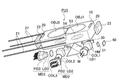
図1は、高密度光ディスクHDとDVDとCDとの何れに対しても適切に情報の記録/再生を行える光ピックアップ装置PU1、2PU1の構成を概略的に示す図である。図示は省略するが、高密度光ディスクHDの光学的仕様は、波長λ1=408nm、保護層の厚さt1=0.0875mm、開口数NA1=0.85であり、DVDの光学的仕様は、波長λ2=658nm、保護層の厚さt2=0.6mm、開口数NA2=0.60であり、CDの光学的仕様は、波長λ3=785nm、保護層の厚さt3=1.2mm、開口数NA3=0.45である。但し、波長、保護層の厚さ、及び開口数の組合せはこれに限られない。
The best mode for carrying out the present invention will be described with reference to the drawings.
[First embodiment]
FIG. 1 is a diagram schematically showing the configuration of optical pickup devices PU1 and PU2 capable of appropriately recording / reproducing information on any of high-density optical disc HD, DVD, and CD. Although not shown, the optical specifications of the high-density optical disc HD are the wavelength λ1 = 408 nm, the protective layer thickness t1 = 0.0875 mm, the numerical aperture NA1 = 0.85, and the optical specification of the DVD is the wavelength λ2 = 658 nm, protective layer thickness t2 = 0.6 mm, numerical aperture NA2 = 0.60, CD optical specifications are wavelength λ3 = 785 nm, protective layer thickness t3 = 1.2 mm, numerical aperture NA3 = 0.45. However, the combination of the wavelength, the thickness of the protective layer, and the numerical aperture is not limited to this.
光ピックアップ装置PU1は、高密度光ディスクHDに対して情報の記録/再生を行う場合に発光され408nmのレーザ光束(第1光束)を射出する青紫色半導体レーザLD1(第1光源)、DVDに対して情報の記録/再生を行う場合に発光され658nmのレーザ光束(第2光束)を射出する赤色半導体レーザLD2(第2光源)と光検出器PD2とが一体化されたDVD用モジュールMD2、CDに対して情報の記録/再生を行う場合に発光され785nmのレーザ光束(第3光束)を射出する赤外半導体レーザLD3(第3光源)と光検出器PD3とが一体化されたCD用モジュールMD3、高密度光ディスク用コリメータCOL1、DVD用コリメータCOL2、CD用コリメータCOL3、偏光ビームスプリッタPBS、ハーフミラーHM、立上げミラーM、高密度光ディスクHD用の第1対物レンズOBJ1、DVD/CD共用の第2対物レンズOBJ2、保持部材10、マグネット20、ワイヤー21、コイル23、モニターPD(フォトダイオード)30、シリンドリカルレンズ31、高密度光ディスクHD用の光検出器40、液晶機構50、開口絞り60等から概略構成されている。
The optical pickup device PU1 emits a 408 nm laser beam (first beam) and emits a 408 nm laser beam (first beam) when recording / reproducing information on the high-density optical disk HD. A DVD module MD2 and CD in which a red semiconductor laser LD2 (second light source) that emits light and emits a 658 nm laser beam (second beam) and a photodetector PD2 are integrated when information is recorded / reproduced. Module for CD in which an infrared semiconductor laser LD3 (third light source) that emits a 785 nm laser beam (third beam) and a photodetector PD3 are integrated when information is recorded / reproduced with respect to MD3, high-density optical disc collimator COL1, DVD collimator COL2, CD collimator COL3, polarization beam splitter PBS, Her Mirror HM, rising mirror M, first objective lens OBJ1 for high density optical disk HD, second objective lens OBJ2 for DVD / CD,
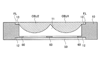
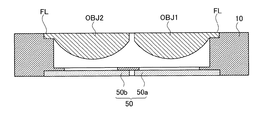
図2に示すように、第1対物レンズOBJ1及び第2対物レンズOBJ2の出射面の周縁には、径方向に延出したフランジ部FLが形成されていると共に、第1対物レンズOBJ1と第2対物レンズOBJ2とはその一部において連続するように一体成形されている。
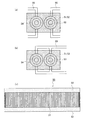
液晶機構50は、球面収差を補正するために設けられるものであり、図3に示すように、電圧の印加により透過する第1〜第3光束に対して位相変化を生じせしめる液晶層51と、液晶層51に電圧を印加するための互いに対向する電極層52とから構成されている。
As shown in FIG. 2, a flange portion FL extending in the radial direction is formed on the periphery of the emission surface of the first objective lens OBJ1 and the second objective lens OBJ2, and the first objective lens OBJ1 and the second objective lens OBJ1 The objective lens OBJ2 is integrally molded so as to be continuous with a part thereof.
The
液晶層51は、第1対物レンズOBJ1の入射面側に配置される同心円状の第1電極パターン53と、第2対物レンズOBJ2の入射面側に配置される同心円状の第2電極パターン54とを備えており、電源(図示略)から各電極パターンに対して電圧を供給することにより、液晶層51中の液晶素子の配向状態が変化し、透過する光束に対して所定の位相を付加させるようになっている。
The
電源と各電極パターンとを図3(a)のように独立した配線55を用いて接続することにより、第1電極パターン53と第2電極パターン54に対する供給電圧を独立して制御することが可能となるので、第1電極パターン53を通過する光束(第1光束)の球面収差補正と第2電極パターン54を通過する光束(第2光束及び第3光束)の球面収差補正を独立して行なうことが可能となり、また、電力を効率よく利用することができる。
また、図3(b)のような第1電極パターン53と第2電極パターン54に対する配線55を共通化することにより、液晶機構50の部品点数を削減できる。
By connecting the power source and each electrode pattern using
Further, by sharing the
保持部材10は、長手方向に開口11を有する矩形状の部材であり、開口11の内面には、高密度光ディスクの開口数に対応した開口絞り60とDVDの開口数に対応した開口絞り60とが同一平面上に取り付けられている。
また、保持部材10の一方の面(光源側の面)に設けた凹部12には液晶機構50が嵌合しており、その他方の面(光ディスク側の面)に設けた凹部13には、第1対物レンズOBJ1及び第2対物レンズOBJ2のフランジ部FLが嵌合している。これにより、高密度光ディスク用の開口絞り60の中心及び第1電極パターン53の中心を第1対物レンズOBJ1の光軸上に一致させ、DVD用の開口絞り60の中心及び第2電極パターン54の中心を第2対物レンズOBJ2の光軸上に一致させた状態で固定することが可能となり、サーボ時における中心軸ずれを防止できる。
尚、ここで、「光軸上に一致」とは、光学的性能を満足するように一致させた状態であれば良く、実質的な一致を意味するものであって、完全に一致するもののみを指すものではない。
The holding
In addition, the
Here, “matching on the optical axis” may be in a state of matching so as to satisfy the optical performance, and means substantial matching, and only matching perfectly. It does not point to.
また、保持部材10が光源側から、液晶機構50、開口絞り60、第1対物レンズOBJ1及び第2対物レンズOBJ2の順に保持することにより、電極層52が保持部材10から露出することになり、電極層52に対する配線作業が容易となる。
液晶機構50により補正することになる球面収差の発生原因としては、例えば、青紫色半導体レーザLD1の製造誤差による波長ばらつき、温度変化に伴う第1対物レンズOBJ1及び第2対物レンズOBJ2の屈折率変化や屈折率分布の変化、光ディスクが2層ディスクや4層ディスク等の多層ディスクである場合の記録/再生時における層間のフォーカスジャンプ、保護層の製造誤差による厚みばらつきや厚み分布のばらつき等によるものが挙げられる。
Further, the holding
The cause of the occurrence of spherical aberration to be corrected by the
このように、液晶機構50により球面収差を補正することにより、例えば、光学系中に配置したビームエキスパンダーを移動させることにより球面収差を補正する場合と比較して、ビームエキスパンダー用のスペースやアクチュエータが不要となり、光ピックアップ装置PU1の小型化・薄型化を実現できる。
Thus, by correcting the spherical aberration by the
マグネット20、ワイヤー21及びコイル23は第1対物レンズOBJ1及び第2対物レンズOBJ2等を保持した状態の保持部材10を駆動させるためのアクチュエータを構成するものであり、本実施の形態においてはムービングマグネット方式のアクチュエータを用いている。ワイヤー21は保持部材10を支持すると共に電極層52に印加する電気信号伝送のために使われる。なお、図4のように、電気信号を2つ伝送できるように1つのワイヤー21に導線21aを2つあるいはそれ以上作成してもよい。
The
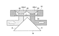
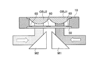
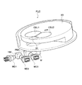
図1及び図5に示すように、立上げミラーMは、稜線を挟んで隣合う2面の反射面Rを持つ三角柱形状であり、第1〜第3光束は反射面Rにおいてその進路が変更され、第1対物レンズOBJ1又は第2対物レンズOBJ2に入射することになる。このように、1つの立上げミラーMに複数の反射面Rを設ける、つまり、第1〜第3光束用の立上げミラーMを共通化することにより、例えば図6に示すように、第1光束専用の立上げミラーM1と第2光束及び第3光束共用の立上げミラーM2を光学系中にそれぞれ配置する場合と比較して、光ピックアップ装置PU1の小型化・薄型化を実現できる。
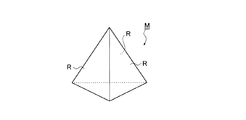
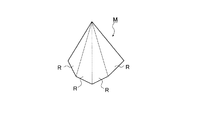
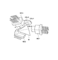
立上げミラーMの形状としては、三角柱以外にも、図7に示すような三角錐、図8に示すような多角錐或いは多角柱など、反射面Rとして利用可能な少なくとも2平面を有する多面体であればよい。
As shown in FIGS. 1 and 5, the rising mirror M has a triangular prism shape having two reflecting surfaces R that are adjacent to each other with a ridge line in between, and the course of the first to third light beams is changed on the reflecting surface R. Then, the light enters the first objective lens OBJ1 or the second objective lens OBJ2. Thus, by providing a plurality of reflecting surfaces R on one rising mirror M, that is, by sharing the rising mirror M for the first to third light beams, for example, as shown in FIG. Compared with the case where the rising mirror M1 dedicated to the light beam and the rising mirror M2 shared with the second light beam and the third light beam are arranged in the optical system, the optical pickup device PU1 can be made smaller and thinner.
The rising mirror M may be a polyhedron having at least two planes that can be used as the reflecting surface R, such as a triangular pyramid as shown in FIG. 7, a polygonal pyramid or a polygonal column as shown in FIG. I just need it.
光ピックアップ装置PU1において、高密度光ディスクHDに対して情報の記録/再生を行う場合には、まず、青紫色半導体レーザLD1を発光させる。青紫色半導体レーザLD1から射出された発散光束は、高密度光ディスク用コリメータCOL1を経て略平行光束とされた後、ハーフミラーHMにより分岐され、一方の光束はモニターPD30に入射してレーザー出射パワーの検出が行われる。
また、他方の光束は三角柱形状の立上げミラーMの反射面Rで反射することによりその進路が変更され、第1電極パターン53を通過する際に所定の位相が付加され、開口絞り60を通過する際にその光束径が規制され、第1対物レンズOBJ1によって高密度光ディスクHDの保護層を介して情報記録面上に球面収差が補正された状態で集光する。
When recording / reproducing information with respect to the high-density optical disk HD in the optical pickup device PU1, first, the blue-violet semiconductor laser LD1 is caused to emit light. The divergent light beam emitted from the blue-violet semiconductor laser LD1 is converted into a substantially parallel light beam through the high-density optical disk collimator COL1, and then branched by the half mirror HM. One light beam is incident on the monitor PD30 and has a laser output power. Detection is performed.
Further, the other light beam is reflected by the reflecting surface R of the triangular prism-shaped rising mirror M, so that the path is changed, and a predetermined phase is added when passing through the
第1対物レンズOBJ1は、その周辺に配置されたアクチュエータによってフォーカシングやトラッキングを行う。情報記録面で情報ピットにより変調された反射光束は、再び第1対物レンズOBJ1、開口絞り60、液晶機構50を透過し、立上げミラーMで反射された後、ハーフミラーHMで分岐され、シリンドリカルレンズ31を通過して高密度光ディスクHD用の光検出器40の受光面上に収束する。そして、高密度光ディスクHD用の光検出器40の出力信号を用いて高密度光ディスクHDに記録された情報を読み取ることができる。
The first objective lens OBJ1 performs focusing and tracking by an actuator disposed around the first objective lens OBJ1. The reflected light beam modulated by the information pits on the information recording surface again passes through the first objective lens OBJ1, the
光ピックアップ装置PU1において、DVDに対して情報の記録/再生を行う場合には、DVD用モジュールMD2を作動させて赤色半導体レーザLD2を発光させる。赤色半導体レーザLD2から射出された発散光束は、その偏光方向が偏光ビームスプリッタPBSにより反射されるようにS偏光とされており、DVD用コリメータCOL2を経て略平行光束とされた後、偏光ビームスプリッタPBSで反射され、立上げミラーMの反射面Rで反射することによりその進路が変更され、第2電極パターン54を通過する際に所定の位相が付加され、開口絞り60を通過する際にその光束径が規制され、第2対物レンズOBJ2によってDVDの保護層を介して情報記録面上に球面収差が補正された状態で集光する。
In the optical pickup device PU1, when recording / reproducing information with respect to a DVD, the DVD module MD2 is operated to emit the red semiconductor laser LD2. The divergent light beam emitted from the red semiconductor laser LD2 is S-polarized so that the polarization direction is reflected by the polarization beam splitter PBS, and after being converted into a substantially parallel light beam through the DVD collimator COL2, the polarization beam splitter Reflected by the PBS and reflected by the reflecting surface R of the rising mirror M, the path is changed, a predetermined phase is added when passing through the
第2対物レンズOBJ2は、その周辺に配置されたアクチュエータによってフォーカシングやトラッキングを行う。情報記録面で情報ピットにより変調された反射光束は、再び第2対物レンズOBJ2、開口絞り60、液晶機構50を透過した後、立上げミラーMで反射して、偏光ビームスプリッタPBSで反射した後、DVD用コリメータCOL2を経てDVD用モジュールMD2の光検出器PD2の受光面上に収束する。そして、光検出器PD2の出力信号を用いてDVDに記録された情報を読み取ることができる。
The second objective lens OBJ2 performs focusing and tracking by an actuator disposed around the second objective lens OBJ2. The reflected light beam modulated by the information pits on the information recording surface is again transmitted through the second objective lens OBJ2, the
光ピックアップ装置PU1において、CDに対して情報の記録/再生を行う場合には、CD用モジュールMD3を作動させて赤外半導体レーザLD3を発光させる。赤外半導体レーザLD3から射出された発散光束は、その偏光方向が偏光ビームスプリッタPBSを透過するようにP偏光とされており、CD用コリメータCOL3を経て略平行光束とされた後、偏光ビームスプリッタPBSを透過し、立上げミラーMの反射面Rで反射することによりその進路が変更される。CD用の第3光束は収差補正の必要度が低いので、必要に応じて第2電極パターン54を通過する際に所定の位相が付加され、開口絞り60を通過し、第2対物レンズOBJ2によってCDの保護層を介して情報記録面上に収差が補正された状態で集光する。
In the optical pickup device PU1, when recording / reproducing information with respect to a CD, the CD module MD3 is operated to cause the infrared semiconductor laser LD3 to emit light. The divergent light beam emitted from the infrared semiconductor laser LD3 is P-polarized so that its polarization direction is transmitted through the polarization beam splitter PBS, and after being converted into a substantially parallel light beam through the CD collimator COL3, the polarization beam splitter The path is changed by passing through the PBS and reflecting by the reflecting surface R of the rising mirror M. Since the third light flux for CD has a low degree of necessity for aberration correction, a predetermined phase is added when passing through the
第2対物レンズOBJ2は、その周辺に配置されたアクチュエータによってフォーカシングやトラッキングを行う。情報記録面で情報ピットにより変調された反射光束は、再び第2対物レンズOBJ2、開口絞り60、液晶機構50を透過した後、立上げミラーMで反射して、偏光ビームスプリッタPBSを透過した後、CD用コリメータCOL3を経てCD用モジュールMD3の光検出器PD3の受光面上に収束する。そして、光検出器PD3の出力信号を用いてCDに記録された情報を読み取ることができる。
The second objective lens OBJ2 performs focusing and tracking by an actuator disposed around the second objective lens OBJ2. The reflected light beam modulated by the information pits on the information recording surface is again transmitted through the second objective lens OBJ2, the
[第2の実施の形態]
図9は、高密度光ディスクHDとDVDとCDとの何れに対しても適切に情報の記録/再生を行える光ピックアップ装置PU2の構成を概略的に示す図である。なお、以下の説明において、上記第1の実施の形態と同一の構成となる部分に関しては同一の符号を付し、その説明を省略する。
[Second Embodiment]
FIG. 9 is a diagram schematically showing a configuration of an optical pickup device PU2 capable of appropriately recording / reproducing information for any of the high density optical disc HD, DVD, and CD. In the following description, the same reference numerals are given to portions having the same configuration as the first embodiment, and the description thereof is omitted.
光ピックアップ装置PU2は、青紫色半導体レーザLD1(第1光源)、赤色半導体レーザLD2(第2光源)、赤外半導体レーザLD3(第3光源)、高密度光ディスク用コリメータCOL1、DVD用コリメータCOL2、CD用コリメータCOL3、第1〜第3ハーフミラーHM1〜HM3、立上げミラーM、高密度光ディスクHD用の第1対物レンズOBJ1、DVD/CD共用の第2対物レンズOBJ2、保持部材10、コイル(図示略)、ワイヤー21、CD用モニターPD70、DVD用モニターPD71、高密度光ディスク用モニターPD72、高密度光ディスクHD用の光検出器40、DVD/CD共用の光検出器41、液晶機構50、開口絞り60等から概略構成されている。
The optical pickup device PU2 includes a blue-violet semiconductor laser LD1 (first light source), a red semiconductor laser LD2 (second light source), an infrared semiconductor laser LD3 (third light source), a high-density optical disc collimator COL1, a DVD collimator COL2, CD collimator COL3, first to third half mirrors HM1 to HM3, rising mirror M, first objective lens OBJ1 for high-density optical disk HD, second objective lens OBJ2 for DVD / CD sharing, holding
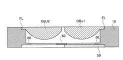
本実施の形態においては、図10に示すように、第1対物レンズOBJ1及び第2対物レンズOBJ2の出射面の周縁には、径方向に延出したフランジ部FLが形成されていると共に、第1対物レンズOBJ1と第2対物レンズOBJ2とは別体に成形されている。
また、本実施の形態においては、第1対物レンズOBJ1の入射面側に配置される高密度光ディスク専用の液晶機構50aと、第2対物レンズOBJ2の入射面側に配置されるDVD/CD専用の液晶機構50bとが別体に配置されており、高密度光ディスク専用の液晶機構50aには第1電極パターン53が配置されており、DVD/CD専用の液晶機構50bには第2電極パターン54が配置されている。これにより、各液晶機構50の表面に対して、透過する光束の波長に対応したARコート(Anti Refledion Coating)を塗布することが可能となり、また、透過する光束の波長に対応した透過率の高い液晶層51を選択できる。
また、図9に示すように、三角柱形状の立上げミラーMは、その最も対物レンズOBJ1、OBJ2に近い稜線Lの部分がカットされた形状となっており、立上げミラーMと保持部材10との間隔を近づけて、光ピックアップ装置PU2の薄型化・小型化に寄与すると共に、フォーカス時の可動範囲を広げている。
In the present embodiment, as shown in FIG. 10, a flange portion FL extending in the radial direction is formed on the periphery of the emission surface of the first objective lens OBJ1 and the second objective lens OBJ2, and The first objective lens OBJ1 and the second objective lens OBJ2 are molded separately.
In the present embodiment, the
As shown in FIG. 9, the triangular prism-shaped rising mirror M has a shape in which the portion of the ridge line L closest to the objective lenses OBJ1 and OBJ2 is cut, and the rising mirror M and the holding
コイル及びワイヤー21は第1対物レンズOBJ1及び第2対物レンズOBJ2等を保持した状態の保持部材10を駆動させるためのアクチュエータを構成するものであり、本実施の形態においてはいわゆるムービングコイル方式のアクチュエータを用いている。1つのワイヤー21には電気信号を2つ伝送できるように図4のように導線21aが2つ存在する。これにより、4ワイヤーによるフォーカス制御信号、トラック制御信号、液晶駆動信号の同時駆動を可能とする。なお、更に多くの信号を伝送するために、1つのワイヤー21に2つ以上の導線21aを作成してもよい。
The coil and
光ピックアップ装置PU2において、高密度光ディスクHDに対して情報の記録/再生を行う場合には、青紫色半導体レーザLD1を発光させる。青紫色半導体レーザLD1から射出された発散光束は、高密度光ディスク用コリメータCOL1を経て略平行光束とされた後、第1ハーフミラーHMにより分岐され、一方の光束は高密度光ディスク用モニターPD72に入射してレーザー出射パワーの検出が行われる。
また、他方の光束は立上げミラーMの反射面Rで反射することによりその進路が変更され、第1電極パターン53を通過する際に所定の位相が付加され、開口絞り60を通過する際にその光束径が規制され、第1対物レンズOBJ1によって高密度光ディスクHDの保護層を介して情報記録面上に収差が補正された状態で集光する。
第1対物レンズOBJ1は、その周辺に配置されたアクチュエータによってフォーカシングやトラッキングを行う。情報記録面で情報ピットにより変調された反射光束は、再び第1対物レンズOBJ1、開口絞り60、液晶機構50を透過し、立上げミラーMで反射した後、第1ハーフミラーHM1を通過して高密度光ディスクHD用の光検出器40の受光面上に収束する。そして、高密度光ディスクHD用の光検出器40の出力信号を用いて高密度光ディスクHDに記録された情報を読み取ることができる。
In the optical pickup device PU2, when recording / reproducing information with respect to the high density optical disk HD, the blue-violet semiconductor laser LD1 is caused to emit light. The divergent light beam emitted from the blue-violet semiconductor laser LD1 is converted into a substantially parallel light beam through the high-density optical disk collimator COL1, and then branched by the first half mirror HM. One light beam enters the high-density optical disk monitor PD72. Then, the laser emission power is detected.
The other light beam is reflected by the reflecting surface R of the rising mirror M to change its path, and a predetermined phase is added when passing through the
The first objective lens OBJ1 performs focusing and tracking by an actuator disposed around the first objective lens OBJ1. The reflected light beam modulated by the information pits on the information recording surface again passes through the first objective lens OBJ1, the
光ピックアップ装置PU2において、DVDに対して情報の記録/再生を行う場合には、赤色半導体レーザLD2を発光させる。赤色半導体レーザLD2から射出された発散光束は、DVD用コリメータCOL2を経て略平行光束とされた後、第2ハーフミラーHM2により分岐され、一方の光束はDVD用モニターPD71に入射してレーザー出射パワーの検出が行われる。
また、他方の光束は立上げミラーMの反射面Rで反射することによりその進路が変更され、第2電極パターン54を通過する際に所定の位相が付加され、開口絞り60を通過する際にその光束径が規制され、第2対物レンズOBJ2によってDVDの保護層を介して情報記録面上に収差が補正された状態で集光する。
In the optical pickup device PU2, when recording / reproducing information with respect to a DVD, the red semiconductor laser LD2 is caused to emit light. The divergent light beam emitted from the red semiconductor laser LD2 is converted into a substantially parallel light beam through the DVD collimator COL2, and then branched by the second half mirror HM2. One light beam is incident on the DVD monitor PD71 and is emitted from the laser. Is detected.
The other light beam is reflected by the reflecting surface R of the rising mirror M to change its path, and a predetermined phase is added when passing through the
第2対物レンズOBJ2は、その周辺に配置されたアクチュエータによってフォーカシングやトラッキングを行う。情報記録面で情報ピットにより変調された反射光束は、再び第2対物レンズOBJ2、開口絞り60、液晶機構50を透過し、立上げミラーMで反射した後、第2及び第1ハーフミラーHM2及びHM1通過してDVD/CD共用の光検出器41の受光面上に収束する。そして、DVD/CD共用の光検出器41の出力信号を用いてDVDに記録された情報を読み取ることができる。
The second objective lens OBJ2 performs focusing and tracking by an actuator disposed around the second objective lens OBJ2. The reflected light flux modulated by the information pits on the information recording surface is transmitted again through the second objective lens OBJ2, the
光ピックアップ装置PU2において、CDに対して情報の記録/再生を行う場合には、赤外半導体レーザLD3を発光させる。赤外半導体レーザLD3から射出された発散光束は、CD用コリメータCOL3を経て略平行光束とされた後、第3ハーフミラーHM3により分岐され、一方の光束はCD用モニターPD70に入射してレーザー出射パワーの検出が行われる。
また、他方の光束は第1及び第2ハーフミラーHM1及びHM2を通過して、立上げミラーMの反射面Rで反射することによりその進路が変更される。CD用の第3光束は収差補正の必要度が低いので、必要に応じて第2電極パターン54を通過する際に所定の位相が付加され、開口絞り60を通過し、第2対物レンズOBJ2によってCDの保護層を介して情報記録面上に収差が補正された状態で集光する。
In the optical pickup device PU2, when recording / reproducing information with respect to a CD, the infrared semiconductor laser LD3 is caused to emit light. The divergent light beam emitted from the infrared semiconductor laser LD3 is converted into a substantially parallel light beam through the CD collimator COL3 and then branched by the third half mirror HM3. One light beam is incident on the CD monitor PD70 and emitted from the laser beam. Power detection is performed.
The other light beam passes through the first and second half mirrors HM1 and HM2 and is reflected by the reflecting surface R of the rising mirror M, so that the course of the light beam is changed. Since the third light flux for CD has a low degree of necessity for aberration correction, a predetermined phase is added when passing through the
第2対物レンズOBJ2は、その周辺に配置されたアクチュエータによってフォーカシングやトラッキングを行う。情報記録面で情報ピットにより変調された反射光束は、再び第2対物レンズOBJ2、開口絞り60、液晶機構50を透過し、立上げミラーMで反射した後、第2及び第1ハーフミラーHM通過してDVD/CD共用の光検出器41の受光面上に収束する。そして、DVD/CD共用の光検出器41の出力信号を用いてCDに記録された情報を読み取ることができる。
The second objective lens OBJ2 performs focusing and tracking by an actuator disposed around the second objective lens OBJ2. The reflected light beam modulated by the information pits on the information recording surface again passes through the second objective lens OBJ2, the
なお、上記実施の形態においては、第1対物レンズOBJ1を高密度光ディスクHD専用、第2対物レンズOBJ2をDVD/CD共用としたが、これに限らず、例えば、第1対物レンズOBJ1を高密度光ディスクHD/DVD共用、第2対物レンズOBJ2をCD専用としたり、第1対物レンズOBJ1を高密度光ディスクHD/CD共用、第2対物レンズOBJ2をDVD専用とするなど、使用する対物レンズと光ディスクの組み合わせは適宜変更可能である。また、これら光ディスク以外に光磁気ディスク等に適用することも可能である。
また、上述のように、高密度光ディスクとしては、ブルーレイディスクBDやHD DVD等が挙げられ、例えば、第1対物レンズOBJ1をHD DVD/DVD共用、第2対物レンズOBJ2をブルーレイディスクBD/CD共用としたり、第1対物レンズOBJ1をHD DVD/ブルーレイディスクBD共用、第2対物レンズOBJ2をDVD/CD共用としたり、第1対物レンズOBJ1をHD DVD/CD共用、第2対物レンズOBJ2をブルーレイディスクBD/DVD共用とするなど、適宜変更可能である。
In the above embodiment, the first objective lens OBJ1 is dedicated to the high-density optical disc HD, and the second objective lens OBJ2 is used for DVD / CD. However, the present invention is not limited to this. For example, the first objective lens OBJ1 is the high-density optical disc. The optical disk HD / DVD is shared, the second objective lens OBJ2 is dedicated to CD, the first objective lens OBJ1 is shared with high-density optical disk HD / CD, and the second objective lens OBJ2 is dedicated to DVD. Combinations can be changed as appropriate. In addition to these optical disks, the present invention can also be applied to magneto-optical disks.
As described above, examples of the high-density optical disc include a Blu-ray Disc BD and HD DVD. For example, the first objective lens OBJ1 is used for HD DVD / DVD sharing, and the second objective lens OBJ2 is used for Blu-ray Disc BD / CD sharing. The first objective lens OBJ1 is used for HD DVD / Blu-ray disc BD, the second objective lens OBJ2 is used for DVD / CD, the first objective lens OBJ1 is used for HD DVD / CD, and the second objective lens OBJ2 is used for Blu-ray disc. It can be changed as appropriate, such as sharing BD / DVD.
また、上記実施の形態においては、液晶層51が、第1対物レンズOBJ1の入射面側に配置される第1電極パターン53と、第2対物レンズOBJ2の入射面側に配置される第2電極パターン54とを備えるものとしたが、一般的に、高密度光ディスクに利用する第1光束に関する収差補正が特に必要となるため、図11に示すように、液晶機構50を、高密度光ディスク専用の第1対物レンズOBJ1側にのみ配置し、第1電極パターン53で第1光束の球面収差を補正し、第2光束及び第3光束に対しては液晶機構50を用いた球面収差補正を行なわない構成としてもよい。この場合、液晶機構50の構成を簡略化することができ、光ピックアップ装置PU2の部品点数を削減することができる。また、液晶の使用体積の減少や液晶の電極パターンのシンプル化によるコスト削減を達成できる。
In the above embodiment, the
また、図12に示すように、円盤状の保持部材80が光ピックアップ装置PU3本体側にその中心回りに回転可能に支持されており、保持部材80が、高密度光ディスク/DVD共用の第1対物レンズOBJ1と、第1対物レンズOBJ1側にのみ配置された液晶機構50と、CD専用の第2対物レンズOBJ2を保持する構成としてもよい。この場合、使用する光ディスクの種類に応じて保持部材80を回転させて、第1対物レンズOBJ1と第2対物レンズOBJ2とを切り替えることになる。
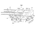
また、上記実施の形態では、光ピックアップ装置PU1、PU2が高密度光ディスクHD専用の第1対物レンズOBJ1とDVD/CD共用の第2対物レンズOBJ2を備える構成としたが、これに限らず、例えば図13に示すように、高密度光ディスクHD専用の第1対物レンズOBJ1、DVD専用の第2対物レンズOBJ2、CD専用の第3対物レンズを円盤状の保持部材10が支持する構成としたり、一体に成形された第1〜第3対物レンズを円盤状の保持部材10が支持する構成としてもよく、この場合、図7に示したような三角錐形状の立上げミラーMの3つの面を反射面Rとし、各面に対して1種類の光束を入射させればよい。
このように、2つ、或いは3つ以上の反射面Rを持つ立上げミラーMを利用することで、1つの反射面Rに対して独立した1つの光学系を組むことが可能となり、例えば図13のように非常にシンプルな光学部品構成でCD、DVD、高密度光ディスクHDの互換光ピックアップ装置を実現でき、光ピックアップ装置の小型・薄型化に貢献できる。なお、図12及び図13中の符号MD1は、青紫色半導体レーザLD1と光検出器とを一体化した高密度光ディスク用モジュールを指す。
また、1つの反射面Rに対して独立した1つもしくは2つ以上の光学系を組めることは、上記のような光ディスク互換用の光ピックアップ装置PU1、PU2だけでなく、例えば、CD/DVD、高密度光ディスクHD、MOのように、光ディスク系と光磁気ディスク系が混在した今までに無い小型薄型光ピックアップ装置を容易に実現可能である。つまり、上述のように、対物レンズを複数の光ディスク間で共用できるように設計することにより、1つの光ピックアップ装置中に組み込む互換数(例えば、CD、DVD、高密度光ディスクHD、MO等の光学系の数)を増やすことができるという利点がある。
Also, as shown in FIG. 12, a disk-shaped holding
In the above embodiment, the optical pickup devices PU1 and PU2 are configured to include the first objective lens OBJ1 dedicated to the high-density optical disk HD and the second objective lens OBJ2 shared with DVD / CD. As shown in FIG. 13, the disk-shaped holding
In this way, by using the rising mirror M having two, or three or more reflecting surfaces R, it becomes possible to form one independent optical system for one reflecting surface R. For example, FIG. As shown in FIG. 13, an optical pickup device compatible with CD, DVD, and high-density optical disc HD can be realized with a very simple optical component configuration, which can contribute to the reduction in size and thickness of the optical pickup device. 12 and 13 indicates a high-density optical disk module in which the blue-violet semiconductor laser LD1 and the photodetector are integrated.
In addition, one or two or more independent optical systems can be assembled with respect to one reflecting surface R in addition to the optical pickup devices PU1 and PU2 compatible with the optical disc as described above, for example, CD / DVD, Like the high-density optical disks HD and MO, it is possible to easily realize an unprecedented small and thin optical pickup device in which an optical disk system and a magneto-optical disk system are mixed. That is, as described above, by designing the objective lens so that it can be shared among a plurality of optical discs, a compatible number (for example, an optical disc such as a CD, a DVD, a high-density optical disc HD, or an MO) can be incorporated into one optical pickup device. There is an advantage that the number of systems) can be increased.
L 稜線
LD1 青紫色半導体レーザ
LD2 赤色半導体レーザ
LD3 赤外半導体レーザ
M ミラー
OBJ1 第1対物レンズ
OBJ2 第2対物レンズ
PU1 光ピックアップ装置
PU2 光ピックアップ装置
PU3 光ピックアップ装置
R 反射面
10 保持部材
50 液晶機構
51 液晶層
52 電極層
53 第1電極パターン
54 第2電極パターン
55 配線
80 保持部材
L Ridge line LD1 Blue-violet semiconductor laser LD2 Red semiconductor laser LD3 Infrared semiconductor laser M Mirror OBJ1 First objective lens OBJ2 Second objective lens PU1 Optical pickup device PU2 Optical pickup device PU3 Optical pickup device R
Claims (9)
Priority Applications (1)
| Application Number | Priority Date | Filing Date | Title |
|---|---|---|---|
| JP2004106700A JP2005293707A (en) | 2004-03-31 | 2004-03-31 | Optical pickup device |
Applications Claiming Priority (1)
| Application Number | Priority Date | Filing Date | Title |
|---|---|---|---|
| JP2004106700A JP2005293707A (en) | 2004-03-31 | 2004-03-31 | Optical pickup device |
Publications (1)
| Publication Number | Publication Date |
|---|---|
| JP2005293707A true JP2005293707A (en) | 2005-10-20 |
Family
ID=35326476
Family Applications (1)
| Application Number | Title | Priority Date | Filing Date |
|---|---|---|---|
| JP2004106700A Pending JP2005293707A (en) | 2004-03-31 | 2004-03-31 | Optical pickup device |
Country Status (1)
| Country | Link |
|---|---|
| JP (1) | JP2005293707A (en) |
Cited By (7)
| Publication number | Priority date | Publication date | Assignee | Title |
|---|---|---|---|---|
| JP2007052858A (en) * | 2005-08-18 | 2007-03-01 | Fujitsu Ltd | Optical disk device |
| WO2007037135A1 (en) * | 2005-09-27 | 2007-04-05 | Konica Minolta Opto, Inc. | Optical pickup and optical information recording medium recorder/reproducer |
| WO2007055166A1 (en) * | 2005-11-08 | 2007-05-18 | Konica Minolta Opto, Inc. | Optical pickup device |
| WO2007055167A1 (en) * | 2005-11-08 | 2007-05-18 | Konica Minolta Opto, Inc. | Optical pickup device |
| WO2007069612A1 (en) * | 2005-12-14 | 2007-06-21 | Matsushita Electric Industrial Co., Ltd. | Optical head and optical information device |
| JP2008070628A (en) * | 2006-09-14 | 2008-03-27 | Citizen Holdings Co Ltd | Liquid crystal optical element and optical pickup |
| US7796477B2 (en) * | 2004-12-16 | 2010-09-14 | Sony Corporation | Optical pick-up device having object lenses for correcting comatic aberration |
-
2004
- 2004-03-31 JP JP2004106700A patent/JP2005293707A/en active Pending
Cited By (8)
| Publication number | Priority date | Publication date | Assignee | Title |
|---|---|---|---|---|
| US7796477B2 (en) * | 2004-12-16 | 2010-09-14 | Sony Corporation | Optical pick-up device having object lenses for correcting comatic aberration |
| JP2007052858A (en) * | 2005-08-18 | 2007-03-01 | Fujitsu Ltd | Optical disk device |
| WO2007037135A1 (en) * | 2005-09-27 | 2007-04-05 | Konica Minolta Opto, Inc. | Optical pickup and optical information recording medium recorder/reproducer |
| WO2007055166A1 (en) * | 2005-11-08 | 2007-05-18 | Konica Minolta Opto, Inc. | Optical pickup device |
| WO2007055167A1 (en) * | 2005-11-08 | 2007-05-18 | Konica Minolta Opto, Inc. | Optical pickup device |
| WO2007069612A1 (en) * | 2005-12-14 | 2007-06-21 | Matsushita Electric Industrial Co., Ltd. | Optical head and optical information device |
| US8144564B2 (en) | 2005-12-14 | 2012-03-27 | Panasonic Corporation | Optical head and optical information device |
| JP2008070628A (en) * | 2006-09-14 | 2008-03-27 | Citizen Holdings Co Ltd | Liquid crystal optical element and optical pickup |
Similar Documents
| Publication | Publication Date | Title |
|---|---|---|
| JP2001209966A (en) | Optical pickup | |
| KR20060003176A (en) | Optical pickup and optical recording and / or reproducing apparatus employing the same | |
| JP2004295983A (en) | Optical head, and optical recording/reproducing device using the same | |
| US20050163015A1 (en) | Optical pickup and recording/reproducing apparatus | |
| CN101165788B (en) | Optical pickup and optical disk drive | |
| JPWO2008075573A1 (en) | Optical element for optical pickup device, optical pickup device, and method of assembling optical pickup device | |
| JP2005032286A (en) | Optical pickup device and optical disk device | |
| KR100509493B1 (en) | Compatible optical pickup | |
| JP2000030288A (en) | Optical pickup element | |
| JP2005293707A (en) | Optical pickup device | |
| JP2005293686A (en) | Optical pickup device | |
| JP4507536B2 (en) | Optical pickup device | |
| JP2007026540A (en) | Optical pickup device and optical information processing device | |
| KR100803592B1 (en) | Compatible optical pickups and optical recording and / or reproducing apparatus employing the same | |
| KR100546351B1 (en) | Compatible optical pickups and optical recording and / or reproducing apparatus employing the same | |
| JP4176070B2 (en) | Optical disc pickup control apparatus and optical disc pickup control method | |
| JP2006147075A (en) | Optical head and optical information recording / reproducing apparatus using the same | |
| JP2009116982A (en) | Information recording / reproducing device | |
| JP5018646B2 (en) | Optical pickup device and optical disk device | |
| CN100394482C (en) | Optical pickup and optical disc drive | |
| JP4640524B2 (en) | Optical disk device | |
| JP4640525B2 (en) | Optical pickup device | |
| JPH10233026A (en) | Optical pickup and optical disk device | |
| JP2007141284A (en) | Optical pickup | |
| JP5339209B2 (en) | Optical pickup device and prism |
Legal Events
| Date | Code | Title | Description |
|---|---|---|---|
| A621 | Written request for application examination |
Free format text: JAPANESE INTERMEDIATE CODE: A621 Effective date: 20070312 |
|
| A977 | Report on retrieval |
Free format text: JAPANESE INTERMEDIATE CODE: A971007 Effective date: 20090303 |
|
| A131 | Notification of reasons for refusal |
Free format text: JAPANESE INTERMEDIATE CODE: A131 Effective date: 20090310 |
|
| A02 | Decision of refusal |
Free format text: JAPANESE INTERMEDIATE CODE: A02 Effective date: 20090630 |