JP2005293691A - Tape cartridge - Google Patents

Tape cartridge Download PDF

Info

Publication number
JP2005293691A
JP2005293691A JP2004105421A JP2004105421A JP2005293691A JP 2005293691 A JP2005293691 A JP 2005293691A JP 2004105421 A JP2004105421 A JP 2004105421A JP 2004105421 A JP2004105421 A JP 2004105421A JP 2005293691 A JP2005293691 A JP 2005293691A
Authority
JP
Japan
Prior art keywords
tape
reel
magnetic
hub
magnetic member
Prior art date
Legal status (The legal status is an assumption and is not a legal conclusion. Google has not performed a legal analysis and makes no representation as to the accuracy of the status listed.)
Pending
Application number
JP2004105421A
Other languages
Japanese (ja)
Inventor
Shuichi Kikuchi
修一 菊地
Kazuo Sasaki
一雄 佐々木
Hitomi Chiba
ひとみ 千葉
Current Assignee (The listed assignees may be inaccurate. Google has not performed a legal analysis and makes no representation or warranty as to the accuracy of the list.)
Sony Corp
Original Assignee
Sony Corp
Priority date (The priority date is an assumption and is not a legal conclusion. Google has not performed a legal analysis and makes no representation as to the accuracy of the date listed.)
Filing date
Publication date
Application filed by Sony Corp filed Critical Sony Corp
Priority to JP2004105421A priority Critical patent/JP2005293691A/en
Publication of JP2005293691A publication Critical patent/JP2005293691A/en
Pending legal-status Critical Current

Links

Images

Landscapes

  • Winding Of Webs (AREA)

Abstract

【課題】 ハブ(テープリール)の回転速度の高速化に対応でき、低コストで生産性に優れたテープカートリッジを提供する。
【解決手段】 磁気テープが巻装されカートリッジケースに回転可能に収容されたハブ57(テープリール56)の内部に、リール回転駆動軸81に磁気吸着する磁性部材76を収納する収納部77を形成する。これにより、テープリール56の回転時、ハブ57に内装された磁性部材76がリール回転駆動軸81上端の永久磁石に磁気吸着して、テープリール56とリール回転駆動軸81との密着状態を保持し、高速回転時における安定性を向上させる。この場合、磁性部材76はハブ57に内装された構成であるので、防錆や脱落等の製品管理負担を削減でき、テープリールを低コストに、かつ生産性高く製造することができる。
【選択図】 図13
PROBLEM TO BE SOLVED: To provide a tape cartridge which can cope with an increase in the rotation speed of a hub (tape reel) and is excellent in productivity at low cost.
A storage portion 77 for storing a magnetic member 76 that is magnetically attracted to a reel rotation drive shaft 81 is formed inside a hub 57 (tape reel 56) wound around a magnetic tape and rotatably accommodated in a cartridge case. To do. As a result, when the tape reel 56 rotates, the magnetic member 76 housed in the hub 57 is magnetically attracted to the permanent magnet at the upper end of the reel rotation drive shaft 81, and the close contact state between the tape reel 56 and the reel rotation drive shaft 81 is maintained. And improve the stability during high-speed rotation. In this case, since the magnetic member 76 is built in the hub 57, the product management burden such as rust prevention and dropping off can be reduced, and the tape reel can be manufactured at low cost and with high productivity.
[Selection] FIG.

Description

本発明は、テープ状記録媒体としての磁気テープが巻装されたハブをカートリッジケースに回転可能に収納してなるテープカートリッジに関し、更に詳しくは、磁気テープの安定した高速走行性を得ることができるテープカートリッジに関する。   The present invention relates to a tape cartridge in which a hub around which a magnetic tape as a tape-shaped recording medium is wound is rotatably housed in a cartridge case, and more specifically, stable high-speed running performance of the magnetic tape can be obtained. The present invention relates to a tape cartridge.

従来より、磁気テープは、情報信号、楽音信号あるいは映像信号等を記録する情報信号記録媒体として、オーディオテープレコーダ、ビデオテープレコーダあるいは情報処理装置の外部記憶装置等の磁気記録再生装置に用いられており、テープリールに巻回されて使用されている。   Conventionally, magnetic tape has been used as an information signal recording medium for recording information signals, music signals, video signals, etc., in magnetic recording / reproducing devices such as audio tape recorders, video tape recorders, or external storage devices of information processing devices. It is wound on a tape reel and used.

図21は、従来より公知のテープカートリッジの第1の構成例であり、上シェル102と下シェル103とを互いに結合してなるカートリッジケース104の内部に、磁気テープ105が巻装された一対のテープリール106,106を回転可能に収納した、いわゆる2リールタイプのテープカートリッジ101の構成を示している。   FIG. 21 is a first configuration example of a conventionally known tape cartridge, and a pair of magnetic tapes 105 wound around a cartridge case 104 formed by coupling an upper shell 102 and a lower shell 103 to each other. 2 shows a configuration of a so-called two-reel type tape cartridge 101 in which tape reels 106 and 106 are rotatably stored.

一方、図22は、従来より公知のテープカートリッジの第2の構成例であり、上シェル112と下シェル113とを互いに結合してなるカートリッジケース114の内部に、磁気テープ115が巻装された単一のテープリール116を回転可能に収納した、いわゆる1リール(単リール)タイプのテープカートリッジ111の構成を示している。   On the other hand, FIG. 22 is a second configuration example of a conventionally known tape cartridge, in which a magnetic tape 115 is wound inside a cartridge case 114 in which an upper shell 112 and a lower shell 113 are coupled to each other. A configuration of a so-called one reel (single reel) type tape cartridge 111 in which a single tape reel 116 is rotatably stored is shown.

上記いずれのタイプのテープリール106,116も、磁気テープ105,115の巻芯部となるハブ106A,116Aと、このハブの下端に形成された円盤状の下フランジ106B,116Bと、ハブの上端に接合された円盤状の上フランジ106C,116Cとで構成されている。なお、これら上下フランジを備えないでハブ単体で磁気テープを巻装するタイプのテープカートリッジも、例えばDDS/DATカセット等のように知られている。   Any of the above types of tape reels 106 and 116 includes hubs 106A and 116A that serve as cores of the magnetic tapes 105 and 115, disk-like lower flanges 106B and 116B formed at the lower ends of the hubs, and upper ends of the hubs. The disc-shaped upper flanges 106C and 116C are joined to each other. Incidentally, a tape cartridge of a type in which a magnetic tape is wound with a single hub without providing these upper and lower flanges is also known, for example, as a DDS / DAT cassette.

これらのテープカートリッジ101,111においては、テープリール106,116をカートリッジケース104,114の内部で回転させて磁気テープ105,115を走行させるようにしている。テープリール106,116の回転駆動は、従来より、テープカートリッジ101,111が装着される記録再生装置のリール回転駆動軸によって行われている。   In these tape cartridges 101 and 111, the tape reels 106 and 116 are rotated inside the cartridge cases 104 and 114 so that the magnetic tapes 105 and 115 run. Conventionally, the tape reels 106 and 116 are rotationally driven by a reel rotational drive shaft of a recording / reproducing apparatus to which the tape cartridges 101 and 111 are mounted.

例えば、第1のテープカートリッジ101におけるテープリール106の下面中央部には、図23に示すように、記録再生装置のリール回転駆動軸107が挿通されるリール孔108Aが設けられている。このリール孔108Aは、筒状に形成されたハブ106Aの内周面に相当する。そして、リール孔108Aの内周面から径内方に突出形成されたチャッキングギヤ108に、リール回転駆動軸107の先端外周面に放射状に形成された係合突起109が係合することによって、リール回転駆動軸107の回転駆動力がテープリール106に伝達される構成とされている。   For example, at the center of the lower surface of the tape reel 106 in the first tape cartridge 101, as shown in FIG. 23, a reel hole 108A through which the reel rotation drive shaft 107 of the recording / reproducing apparatus is inserted is provided. The reel hole 108A corresponds to the inner peripheral surface of the hub 106A formed in a cylindrical shape. Then, the engaging projections 109 formed radially on the outer peripheral surface of the tip end of the reel rotation drive shaft 107 are engaged with the chucking gear 108 formed to protrude radially inward from the inner peripheral surface of the reel hole 108A. The rotation driving force of the reel rotation driving shaft 107 is transmitted to the tape reel 106.

一方、第2のテープカートリッジ111におけるテープリール116にあっては、その下面中央部に、図24に示すように、記録再生装置のリール回転駆動軸117と係合する環状のチャッキングギヤ118が設けられている。このチャッキングギヤ118の形成領域は、筒状に形成されたハブ116Aの底部領域に相当する。そして、このチャッキングギヤ118に、リール回転駆動軸117の先端に環状に形成された係合突起119が係合することによって、リール回転駆動軸117の回転駆動力がテープリール116に伝達される構成とされている。   On the other hand, the tape reel 116 in the second tape cartridge 111 has an annular chucking gear 118 that engages with the reel rotation drive shaft 117 of the recording / reproducing apparatus, as shown in FIG. Is provided. The formation region of the chucking gear 118 corresponds to the bottom region of the hub 116A formed in a cylindrical shape. Then, the chucking gear 118 is engaged with an engagement protrusion 119 formed in an annular shape at the tip of the reel rotation drive shaft 117, whereby the rotation drive force of the reel rotation drive shaft 117 is transmitted to the tape reel 116. It is configured.

特開2002−304865号公報JP 2002-304865 A

ところで、磁気テープ記録再生装置においては、磁気テープに記録された情報信号の高速アクセスを可能とするために、巻戻し動作あるいは高速送り動作に際しては、通常の磁気テープの走行速度に対して数倍ものスピード(例えば数メートル/秒)で磁気テープを走行させている。
特に、近年においては、1巻のカートリッジに数百ギガバイトもの情報を記録できるテープカートリッジも開発されており、アクセス速度向上のために磁気テープの走行スピードは更に高速化されている(例えば数十メートル/秒)。
By the way, in the magnetic tape recording / reproducing apparatus, in order to enable high-speed access of information signals recorded on the magnetic tape, the rewinding operation or the high-speed feeding operation is several times the normal traveling speed of the magnetic tape. The magnetic tape is running at a high speed (for example, several meters / second).
In particular, in recent years, tape cartridges capable of recording hundreds of gigabytes of information on one cartridge have been developed, and the traveling speed of magnetic tape has been further increased (for example, several tens of meters) in order to improve access speed. / Sec).

このように、高速で回転されるテープリールにおいては、その回転時、テープリールとリール回転駆動軸とが精度良く係合される必要があり、かつ、係合後及び回転駆動中にあっては、テープリールとリール回転駆動軸とが相互に密着し自由に挿脱したり揺動することなく、その密着状態を保持する必要がある。   As described above, in a tape reel rotated at high speed, the tape reel and the reel rotation drive shaft need to be accurately engaged during the rotation, and after the engagement and during rotation drive, The tape reel and the reel rotation drive shaft need to be kept in close contact with each other without being freely inserted and removed or swinging.

しかしながら、従来のテープカートリッジにおいては、テープリールとリール回転駆動軸との間を強固に密着させる手段を有していないので、テープリールとリール回転駆動軸との間の軸心位置のバラツキや、テープリールとリール回転駆動軸との間の係合のバラツキ等に起因して発生するテープリールの軸振れ、面振れ、周振れ等により、磁気テープの安定した高速走行性を確保することが難しいと共に、アクセス速度向上のための磁気テープの更なる高速回転化に対応することができないという問題がある。   However, in the conventional tape cartridge, since there is no means for firmly adhering between the tape reel and the reel rotation drive shaft, the variation in the axial center position between the tape reel and the reel rotation drive shaft, It is difficult to ensure a stable high-speed running property of the magnetic tape due to the tape reel shaft runout, surface runout, circumferential runout, etc. caused by variations in the engagement between the tape reel and the reel rotation drive shaft. At the same time, there is a problem that the magnetic tape cannot be further rotated at a higher speed for improving the access speed.

また、テープリールとリール回転駆動軸とが強固に密着されていないと、テープリールの回転駆動時において、テープリールの駆動方向の変化すなわち巻取りから巻出し(又はその逆)の駆動切替があった場合、記録再生装置内における磁気テープの位置等に変化が生じ、高精度なテープ走行が阻害されてしまうことになる。   Further, if the tape reel and the reel rotation drive shaft are not firmly adhered, there is a change in the tape reel drive direction, that is, drive switching from winding to unwinding (or vice versa) when the tape reel is driven to rotate. In this case, a change occurs in the position of the magnetic tape in the recording / reproducing apparatus, and high-accuracy tape running is obstructed.

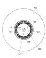
なお、上記特許文献1には、テープリールの下面中央部にリール回転駆動軸の先端に磁気吸着する磁性金属板を配置することにより、テープリールとリール回転駆動軸との密着を図る構成が開示されている。図25に示すように、この種のテープリール120は、下フランジの下面中央部に、磁性材料でなる環状の金属プレート122をインサート成形により外装してなるもので、金属プレート122の外周側には、リール回転駆動軸と係合するチャッキングギヤ121が略環状に形成され、金属プレート122の内周縁部122aには、テープリール120に対する当該金属プレート122の位置決め用の突起124が当接している。また、金属プレート122の面内複数箇所には、当該金属プレート122の脱落防止用の抜け止め部123が貫通形成されている。   Patent Document 1 discloses a configuration in which a magnetic metal plate that is magnetically attracted to the tip of the reel rotation drive shaft is disposed at the center of the lower surface of the tape reel so as to closely contact the tape reel and the reel rotation drive shaft. Has been. As shown in FIG. 25, this type of tape reel 120 is formed by inserting an annular metal plate 122 made of a magnetic material at the center of the lower surface of the lower flange by insert molding. The chucking gear 121 that engages with the reel rotation drive shaft is formed in a substantially annular shape, and the protrusion 124 for positioning the metal plate 122 with respect to the tape reel 120 abuts on the inner peripheral edge 122a of the metal plate 122. Yes. In addition, the metal plate 122 is formed with through holes 123 that prevent the metal plate 122 from dropping out at a plurality of locations in the surface of the metal plate 122.

上記特許文献1の構成では、テープリール120の回転時における重心バランスを確保するため、金属プレート122はテープリール120の下面中央部に対して高精度に取り付けられる必要がある。そのために金属プレート122の内周側を開口させ、これに位置決め用突起124を当接させて、テープリール120に対する金属プレート122の高精度な位置決めを確保している。しかしながら、磁力が最も強く出現する金属プレート122の中心部を位置決めのために開口させざるを得ない構成であるので、リール回転駆動軸との磁気吸着作用を有効に活用しているとは言い難く、テープリールの回転速度の更なる高速化に対応できなくなる。   In the configuration of Patent Document 1, the metal plate 122 needs to be attached to the center portion of the lower surface of the tape reel 120 with high accuracy in order to ensure the balance of the center of gravity when the tape reel 120 rotates. For this purpose, the inner peripheral side of the metal plate 122 is opened, and the positioning projection 124 is brought into contact therewith, so that the metal plate 122 can be positioned with high accuracy with respect to the tape reel 120. However, since the central portion of the metal plate 122 where the magnetic force appears most strongly has to be opened for positioning, it is difficult to say that the magnetic attraction action with the reel rotation drive shaft is effectively utilized. It becomes impossible to cope with further increase in the rotation speed of the tape reel.

また、テープリール120の下面中央部に磁性金属プレート122をインサート成形により一体化する従来の構成においては、テープリール120からの金属プレート122の脱落防止対策が必須となる。従って、テープリールの高速回転化に対応するためには、金属プレートの抜け止め構造がより一層重要な設計課題となると同時に、更に高い信頼性が要求されることになり、これが原因でテープリールの生産性及び製造コストが悪化するおそれがある。更に、金属プレート122が全体的にテープリール120の下面に露出しているため、防錆処理が必須となり、これが原因でテープリール及びテープカートリッジの高コスト化を引き起こしている。   Further, in the conventional configuration in which the magnetic metal plate 122 is integrated with the center portion of the lower surface of the tape reel 120 by insert molding, measures to prevent the metal plate 122 from falling off the tape reel 120 are essential. Therefore, in order to cope with the high-speed rotation of the tape reel, the metal plate retaining structure becomes an even more important design issue, and at the same time, higher reliability is required. Productivity and manufacturing cost may be deteriorated. Furthermore, since the metal plate 122 is entirely exposed on the lower surface of the tape reel 120, rust prevention treatment is essential, which causes an increase in the cost of the tape reel and the tape cartridge.

本発明は上述の問題に鑑みてなされ、ハブ(テープリール)の回転速度の更なる高速化にも十分に対応でき、低コストで生産性に優れたテープカートリッジを提供することを課題とする。   The present invention has been made in view of the above-described problems, and an object of the present invention is to provide a tape cartridge that can sufficiently cope with a further increase in the rotation speed of a hub (tape reel) and that is low in cost and excellent in productivity.

以上の課題を解決するに当たり、本発明のテープカートリッジは、カートリッジケースと、磁気テープが巻装されカートリッジケースに回転可能に収容されたハブと、記録再生装置の回転駆動軸に磁気吸着する磁性部材と、ハブの内部に形成され上記磁性部材が収納される収納部とを備えている。   In solving the above problems, the tape cartridge of the present invention includes a cartridge case, a hub around which a magnetic tape is wound and rotatably accommodated in the cartridge case, and a magnetic member that is magnetically attracted to the rotation drive shaft of the recording / reproducing apparatus. And a storage portion that is formed inside the hub and stores the magnetic member.

本発明では、記録再生装置の回転駆動軸に磁気吸着する磁性部材を、ハブの内部に形成した収納部に内装させる構成としたことにより、ハブとリール回転駆動軸とを精度良く係合させ、かつ、係合後及び回転駆動中にあっては、ハブとリール回転駆動軸との間を強固に密着させ、自由に挿脱したり揺動することなくその密着状態を保持することができるようになり、ハブ回転速度の更なる高速化にも十分に対応することが可能となると共に、ハブの駆動方向が変化した場合にも、高精度なテープ走行性を確保することができる。   In the present invention, the magnetic member that is magnetically attracted to the rotation drive shaft of the recording / reproducing apparatus is configured to be housed in the housing portion formed inside the hub, so that the hub and the reel rotation drive shaft are accurately engaged, In addition, after the engagement and during the rotation drive, the hub and the reel rotation drive shaft are firmly brought into close contact so that the contact state can be maintained without being freely inserted / removed or swung. Accordingly, it is possible to sufficiently cope with further increase in the hub rotation speed, and it is possible to ensure highly accurate tape running even when the driving direction of the hub is changed.

また、上記磁性部材をハブの内部の収納部に収納させる構成であるので、当該磁性部材のハブからの脱落防止対策を別途要することなく高い信頼性をもってテープカートリッジを構成することができる。更に、ハブに対する磁性部材の位置決め機構も特別要することなく構成できるので、磁気吸着力を向上させて、ハブ回転速度の高速化に至っても、ハブと回転駆動軸との密着力を確保し、ハブの安定した回転駆動を実現できる。更に又、磁性部材がハブに内装される構成であるので、磁性部材に対する防錆処理は特別要求されず、また、磁性部材に高い品質が要求されることもないので、テープカートリッジを安価に製造することが可能となる。   Further, since the magnetic member is housed in the housing portion inside the hub, the tape cartridge can be constructed with high reliability without requiring a separate measure for preventing the magnetic member from falling off the hub. In addition, since the magnetic member positioning mechanism with respect to the hub can be configured without any special requirement, the magnetic attraction force can be improved and the contact force between the hub and the rotary drive shaft can be secured even if the hub rotation speed is increased. Stable rotation drive can be realized. Furthermore, since the magnetic member is built in the hub, no special anti-rust treatment is required for the magnetic member, and high quality is not required for the magnetic member. It becomes possible to do.

なお、本発明において「ハブ」とは、磁気テープの巻芯部を意味し、この巻芯部のみで構成される形態は勿論、巻芯部の上端及び/又は下端から径外方へ延在するフランジが形成されてなるリール(テープリール)としての形態も、本発明の適用範囲内である。   In the present invention, the “hub” means the core portion of the magnetic tape, and of course, it is composed of only the core portion and extends outward from the upper end and / or lower end of the core portion. A form as a reel (tape reel) formed with a flange to be formed is also within the scope of application of the present invention.

以上のように、本発明のテープカートリッジによれば、記録再生装置の回転駆動軸と磁気吸着させる磁性部材をハブに内装させる構成としたので、磁性部材の脱落及び回転駆動軸との密着力低下の懸念を払拭して、ハブの高速回転化に十分に対応することが可能となり、これにより磁気テープの高速走行時の安定性の向上を図ることができる。更に、低コストかつ生産性高くテープカートリッジを製造することが可能となる。   As described above, according to the tape cartridge of the present invention, the magnetic member to be magnetically attracted to the rotational drive shaft of the recording / reproducing apparatus is built in the hub, so that the magnetic member is detached and the adhesion to the rotational drive shaft is reduced. Therefore, it is possible to sufficiently cope with the high-speed rotation of the hub, thereby improving the stability of the magnetic tape during high-speed running. Furthermore, it becomes possible to manufacture a tape cartridge with low cost and high productivity.

以下、本発明の実施の形態について図面を参照して説明する。   Hereinafter, embodiments of the present invention will be described with reference to the drawings.

(第1の実施の形態)
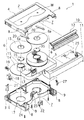
図1は本発明の第1の実施の形態によるテープカートリッジ1の構成を示す分解斜視図である。テープカートリッジ1は、例えば合成樹脂材料でなる上シェル2と下シェル3とを互いに結合してなるカートリッジケース4の内部に、テープ状記録媒体としての磁気テープ5を巻装した一対のテープリール6,6を左右に離間して回転可能に収納して構成されている。
(First embodiment)
FIG. 1 is an exploded perspective view showing the configuration of the tape cartridge 1 according to the first embodiment of the present invention. The tape cartridge 1 includes a pair of tape reels 6 in which a magnetic tape 5 as a tape-shaped recording medium is wound inside a cartridge case 4 formed by coupling an upper shell 2 and a lower shell 3 made of, for example, a synthetic resin material. , 6 are configured to be housed so as to be rotatable apart from each other on the left and right.

カートリッジケース4の前部には、前方及び上下に開放されるテープローディング用の空間部(マウス部)7が形成されている。磁気テープ5は、この空間部を横切るように、カートリッジケース4の前部から突出形成された一対の角筒状のテープ引出し部8,8間に架け渡されることによって構成され、空間部7を区画し、その下シェル3側にはテープ走行領域を構成するテープガイド9,9がそれぞれ設けられている。   In the front part of the cartridge case 4, a tape loading space (mouse part) 7 that is opened forward and vertically is formed. The magnetic tape 5 is constructed by being bridged between a pair of rectangular tube-shaped tape drawer portions 8 and 8 that are formed so as to protrude from the front portion of the cartridge case 4 so as to cross the space portion. The tape guides 9 and 9 constituting the tape running area are provided on the lower shell 3 side.

空間部7を横切る磁気テープ5は、非使用時、リッド構体10により覆われており、磁気テープ5への塵埃の付着や手指の接触による油脂等の付着が防止されるようになっている。リッド構体10は、磁気テープ5の前面側を覆うフロントリッド11と、磁気テープ5の背面側を覆うバックリッド12との組合せ体で構成されている。フロントリッド11は、その両端内面側に突出形成された回動軸25のまわりに回動可能とされ、カートリッジ非使用時はリッドスプリング26の付勢力により空間部7を閉塞すると共に、リッドロック部材27によって不用意な開放動作が規制される。   The magnetic tape 5 traversing the space 7 is covered with the lid structure 10 when not in use, so that adhesion of dust to the magnetic tape 5 and adhesion of oils and fats due to finger contact are prevented. The lid structure 10 includes a combination of a front lid 11 that covers the front side of the magnetic tape 5 and a back lid 12 that covers the back side of the magnetic tape 5. The front lid 11 is rotatable around a rotation shaft 25 that is formed to project from the inner surfaces of both ends. When the cartridge is not used, the space portion 7 is closed by the urging force of the lid spring 26 and a lid lock member is provided. 27 regulates an inadvertent opening operation.

一対のテープリール6,6はそれぞれ上フランジ13と下フランジ14との接合体でなり、下フランジ14には、磁気テープ5の巻芯部を構成するハブ15が一体形成されている。磁気テープ5は、各テープリール6,6のハブ15に対して、磁性面を外向きに透明なリーダーテープLTを介してクランパ16により一体化されている。   Each of the pair of tape reels 6 and 6 is a joined body of an upper flange 13 and a lower flange 14, and a hub 15 that forms a core portion of the magnetic tape 5 is integrally formed on the lower flange 14. The magnetic tape 5 is integrated with the hub 15 of each of the tape reels 6 and 6 by a clamper 16 via a leader tape LT that is transparent with the magnetic surface facing outward.

カートリッジケース4の内部には、更に、リールロック部材18、リールロックスプリング19、一対のリールスプリング20,20、セイフティタブ21、ランプキャップ22等が収納され、上シェル2の内面部には透明材料でなる窓部材Wが接合されている。   The cartridge case 4 further contains a reel lock member 18, a reel lock spring 19, a pair of reel springs 20, 20, a safety tab 21, a lamp cap 22, etc., and a transparent material on the inner surface of the upper shell 2. The window member W which consists of is joined.

リールロック部材18は、テープカートリッジ1の非使用時、リールロックスプリング19の付勢力を受けて、テープリール6,6(下フランジ14,14)の外周面に形成されているギヤに係合してテープリール6,6の回転を規制し、カートリッジケース4の内部における磁気テープ5の弛みを防止する。   When the tape cartridge 1 is not used, the reel lock member 18 receives a biasing force of the reel lock spring 19 and engages with a gear formed on the outer peripheral surface of the tape reels 6 and 6 (lower flanges 14 and 14). Thus, the rotation of the tape reels 6 and 6 is restricted, and the slack of the magnetic tape 5 inside the cartridge case 4 is prevented.

リールスプリング20,20は、上シェル2の内面側に取り付けられており、テープリール6,6の上面中央部に突設されたバネ受け部6aを押圧している。そして、非使用時にはテープリール6,6を下シェル3側に押し付けて当該テープリール6,6のガタツキを抑える。また、カートリッジ使用時においては、テープリール6,6をリール回転駆動軸に押し付けて当該テープリール6,6の回転の安定化を図る。   The reel springs 20, 20 are attached to the inner surface side of the upper shell 2 and press the spring receiving portions 6 a protruding from the center of the upper surface of the tape reels 6, 6. When not in use, the tape reels 6 and 6 are pressed against the side of the lower shell 3 to suppress backlash of the tape reels 6 and 6. When the cartridge is used, the tape reels 6 and 6 are pressed against the reel rotation drive shaft to stabilize the rotation of the tape reels 6 and 6.

セイフティタブ21は、磁気テープ5に記録された情報の誤消去や誤記録を防止するためのもので、カートリッジケース4の背面側において記録可能位置と記録不可能位置との間をスライド自在に組み込まれている。   The safety tab 21 is for preventing erroneous erasure and erroneous recording of information recorded on the magnetic tape 5 and is slidably incorporated between a recordable position and a non-recordable position on the back side of the cartridge case 4. It is.

ランプキャップ22は、記録再生装置の内部においてカートリッジケース4の前面側中央の筒状部23に挿入されるテープ検出用の発光体を覆う透明な部材であり、発光体からの照射光をテープ引出し部8,8の外面に設けられた検出窓24へ導く機能を有する。   The lamp cap 22 is a transparent member that covers the light emitter for tape detection inserted into the cylindrical portion 23 at the center of the front side of the cartridge case 4 inside the recording / reproducing apparatus, and draws the irradiation light from the light emitter to the tape. It has a function of leading to the detection window 24 provided on the outer surface of the portions 8 and 8.

次に、テープリール6の詳細について図2〜図5を参照して説明する。
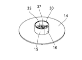
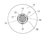
ここで、図2はテープリール6の上フランジ13を取り外して見たときの斜視図、図3は、テープリール6を下フランジ側から見た斜視図、図4はリール回転駆動軸33と係合しているテープリール6の側断面図、図5はテープリール6の上フランジ13を取り外して見たときの平面図である。
Next, details of the tape reel 6 will be described with reference to FIGS.
2 is a perspective view of the tape reel 6 when the upper flange 13 is removed, FIG. 3 is a perspective view of the tape reel 6 viewed from the lower flange side, and FIG. FIG. 5 is a plan view when the tape reel 6 is viewed with the upper flange 13 removed.

上述のように、テープリール6は、上フランジ13、下フランジ14及びハブ15で構成されている。これら上フランジ13、下フランジ14及びハブ15は、それぞれ、ポリカーボネート(PC)樹脂、ポリスチレン(PS)樹脂、ポリアセタール(POM)樹脂、アクリロニトリルスチロール(AS)樹脂等の合成樹脂材料で形成できるが、これ以外に、アルミニウムあるいはチタン、マグネシウム等の金属材料や、鉄あるいは磁性ステンレス鋼(SUS430等)といった磁性材料等で構成することもできる。   As described above, the tape reel 6 includes the upper flange 13, the lower flange 14, and the hub 15. The upper flange 13, the lower flange 14 and the hub 15 can be made of a synthetic resin material such as polycarbonate (PC) resin, polystyrene (PS) resin, polyacetal (POM) resin, acrylonitrile styrene (AS) resin, etc. In addition, it can be made of a metal material such as aluminum, titanium or magnesium, or a magnetic material such as iron or magnetic stainless steel (SUS430 or the like).

また、本実施の形態において、ハブ15は、下フランジ14とは一体的に形成され、上フランジ13とは、ハブ15の上端に形成された溶着リブ30を介しての超音波接合等により一体化されているが、勿論、これらを別部材で構成してもよい。特に、下フランジ14を磁性材料で形成することにより、後述するようにリール回転駆動軸より発生する磁界を遮蔽して磁気テープ5に対する磁気的な影響を回避することができる。この場合、下フランジ14は、金属材料等の薄板を円盤状に打抜き形成したり型成形で構成できる。また、上記磁性材料は、合成樹脂材料中に磁性金属フィラーを含有させた複合材料や、表面に磁性層を形成したものでもよい。   In the present embodiment, the hub 15 is formed integrally with the lower flange 14, and the upper flange 13 is integrally formed by ultrasonic bonding or the like via a welding rib 30 formed at the upper end of the hub 15. Of course, these may be constituted by separate members. In particular, by forming the lower flange 14 of a magnetic material, it is possible to shield a magnetic field generated from the reel rotation drive shaft and avoid magnetic influence on the magnetic tape 5 as will be described later. In this case, the lower flange 14 can be formed by stamping or forming a thin plate of a metal material or the like into a disk shape. The magnetic material may be a composite material in which a magnetic metal filler is contained in a synthetic resin material or a magnetic layer formed on the surface.

テープリール6の下面中央部には、記録再生装置側のリール回転駆動軸33と係合するチャッキングギヤ31が駆動係合部として形成されている。チャッキングギヤ31は、ハブ15の底部外面側に形成されており、リール回転駆動軸33の先端と係合し、当該リール回転駆動軸33の回転駆動力がこれらチャッキングギヤ31との係合機構を介してテープリール6に伝達されるようになっている。   A chucking gear 31 that engages with the reel rotation drive shaft 33 on the recording / reproducing apparatus side is formed as a drive engagement portion at the center of the lower surface of the tape reel 6. The chucking gear 31 is formed on the bottom outer surface side of the hub 15 and is engaged with the tip of the reel rotation drive shaft 33, and the rotation driving force of the reel rotation drive shaft 33 is engaged with these chucking gears 31. It is transmitted to the tape reel 6 through a mechanism.

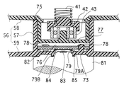
テープリール6とリール回転駆動軸33との間の密着性を高めるため、テープリール6には、リール回転駆動軸33に対して磁気吸着する磁性部材35が設けられている(図4,図5)。一方、リール回転駆動軸33の先端には、上記磁性部材35に磁気吸着力を発生させる永久磁石34が組み込まれている。   In order to improve the adhesion between the tape reel 6 and the reel rotation drive shaft 33, the tape reel 6 is provided with a magnetic member 35 that is magnetically attracted to the reel rotation drive shaft 33 (FIGS. 4 and 5). ). On the other hand, a permanent magnet 34 for generating a magnetic attractive force on the magnetic member 35 is incorporated at the tip of the reel rotation drive shaft 33.

従って、テープリール6とリール回転駆動軸33とが精度良く係合し、係合後及び回転駆動中にあっては、テープリール6とリール回転駆動軸33との間が強固に密着して、自由に挿脱したり揺動することなくその密着状態が保持される。これにより、テープリール6とリール回転駆動軸33との間の軸心位置のバラツキや、テープリール6とリール回転駆動軸33との間の係合のバラツキ等に起因して発生するテープリール6の軸振れ、面振れ、周振れ等を防止して、磁気テープ5の安定した高速走行性を確保することができる共に、アクセス速度向上のため、テープリール6の更なる高速回転化にも十分に対応することが可能となる。   Therefore, the tape reel 6 and the reel rotation drive shaft 33 are engaged with each other with high precision, and the tape reel 6 and the reel rotation drive shaft 33 are in close contact with each other after the engagement and during the rotation drive. The close contact state is maintained without being freely inserted and removed or rocked. As a result, the tape reel 6 generated due to variations in the axial center position between the tape reel 6 and the reel rotation drive shaft 33, variations in engagement between the tape reel 6 and the reel rotation drive shaft 33, and the like. Can prevent the shaft runout, surface runout, and circumferential runout of the magnetic tape 5 to ensure stable high-speed running performance, and at the same time, the tape reel 6 can be rotated at a higher speed to improve the access speed. It becomes possible to cope with.

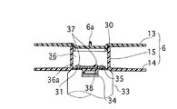
図4及び図5に示したように、磁性部材35は、ハブ15に内装されている。ハブ15は筒状を有し、ハブ15の内部には、磁性部材35を収納する収納部36が形成されている。収納部36の底部36aは平坦で、ここにハブ15の内径よりも小径な円盤状の磁性部材35が載置されている。特に本実施の形態では、図5に示すように、ハブ15の周面に形成されたクランパ16組込用の凹所32にほぼ内接する大きさに、磁性部材35の外径が設定されている。   As shown in FIGS. 4 and 5, the magnetic member 35 is built in the hub 15. The hub 15 has a cylindrical shape, and a housing portion 36 for housing the magnetic member 35 is formed inside the hub 15. The bottom portion 36 a of the storage portion 36 is flat, and a disk-like magnetic member 35 having a smaller diameter than the inner diameter of the hub 15 is placed thereon. In particular, in the present embodiment, as shown in FIG. 5, the outer diameter of the magnetic member 35 is set to a size almost inscribed in the recess 32 for assembling the clamper 16 formed on the peripheral surface of the hub 15. Yes.

これにより、テープリール6の回転時における遠心力及びイナーシャ(慣性)の影響を小さくすることが可能となるので、これに起因するテープリール6の回転振動を低く抑えることが可能となり、高速信頼性を高くすることができる。また、磁性部材35とリール回転駆動軸33との間に形成される磁界を、ハブ15に巻装されている磁気テープ5から遠ざけることができるので、磁気テープ5が受ける磁気的影響を抑止できる。   This makes it possible to reduce the influence of centrifugal force and inertia (inertia) during the rotation of the tape reel 6, so that it is possible to suppress the rotational vibration of the tape reel 6 resulting from this, and high speed reliability. Can be high. Further, since the magnetic field formed between the magnetic member 35 and the reel rotation drive shaft 33 can be kept away from the magnetic tape 5 wound around the hub 15, the magnetic influence on the magnetic tape 5 can be suppressed. .

ここで、磁性部材35は、鉄や磁性ステンレス鋼(例えばSUS430)、珪素鋼板、パーマロイ等の軟磁気特性を有する強磁性材料で形成され、打抜きプレス等の機械加工により容易に製造できる。また、例えばNiめっき等、防錆等のための特殊な表面処理は必要に応じて省略でき、厳しい寸法精度も必要とされないので、低コストに製造できる。更に、磁性部材35の面内中央部に位置決めのための加工を必要としないので、磁性部材35の中央部に出現する強力な磁気吸着力を有効に活用することが可能となり、高速走行時におけるテープリール6とリール回転駆動軸33との密着性を高めて磁気テープ5の走行安定性の向上を図ることができる。   Here, the magnetic member 35 is formed of a ferromagnetic material having soft magnetic properties such as iron, magnetic stainless steel (for example, SUS430), a silicon steel plate, and permalloy, and can be easily manufactured by machining such as a punching press. In addition, special surface treatment for rust prevention such as Ni plating can be omitted as necessary, and strict dimensional accuracy is not required, so that it can be manufactured at low cost. Furthermore, since no positioning process is required at the central portion of the magnetic member 35, it is possible to effectively utilize the strong magnetic attractive force that appears at the central portion of the magnetic member 35. It is possible to improve the running stability of the magnetic tape 5 by improving the adhesion between the tape reel 6 and the reel rotation drive shaft 33.

なお、磁性部材35は円盤状に限らず、多角形状でもよい。また、磁性部材35は板状に限らず、例えばブロック状のものも適用可能であるが、テープリール6の安定した回転姿勢を確保するために、テープリール6の重心位置はなるべく低くなるように構成されているのが好ましい。   The magnetic member 35 is not limited to a disk shape, and may be a polygonal shape. In addition, the magnetic member 35 is not limited to a plate shape, and for example, a block shape can be applied. However, in order to ensure a stable rotation posture of the tape reel 6, the position of the center of gravity of the tape reel 6 is made as low as possible. Preferably, it is configured.

磁性部材35は、図4に示すように、収納部36の底部36aにかしめ固定することができる。この場合、収納部36の底部36aに、かしめ固定用の複数本の突起37を立設し、これに対応して、磁性部材35には、突起37が挿通される孔38を貫通形成しておく。そして、磁性部材35を収納部36に収納する際、孔38に突起37を挿通させ、磁性部材35の上面から突出した突起37の先端に例えば超音波振動を付与して溶融拡径させることにより、磁性部材35を収納部底部36aへ固着できる。   As shown in FIG. 4, the magnetic member 35 can be caulked and fixed to the bottom portion 36 a of the storage portion 36. In this case, a plurality of caulking fixing projections 37 are provided upright on the bottom portion 36a of the storage portion 36, and correspondingly, the magnetic member 35 is formed with a hole 38 through which the projection 37 is inserted. deep. When the magnetic member 35 is stored in the storage portion 36, the protrusion 37 is inserted into the hole 38, and, for example, ultrasonic vibration is applied to the tip of the protrusion 37 protruding from the upper surface of the magnetic member 35 to melt and expand the diameter. The magnetic member 35 can be fixed to the storage portion bottom 36a.

なお、かしめ用の突起37は、テープリール6の回転軸の軸心を中心とする同一円周上に配置形成する。これにより、テープリール6の回転時における動的安定性(ダイナミックバランス)を確保して、高速信頼性を確保することができる。   The caulking projections 37 are arranged and formed on the same circumference centered on the axis of the rotation axis of the tape reel 6. Thereby, the dynamic stability (dynamic balance) at the time of rotation of the tape reel 6 is ensured, and high-speed reliability can be ensured.

収納部36における磁性部材35の支持は、上記かしめ固定に限らず、例えば図6に示すように、収納部36の底部36aに載置されている磁性部材35の上面と対向する姿勢保持体39を上フランジ13の中央部内面に設け、この姿勢保持体39と磁性部材35との当接作用によって、磁性部材35の横臥姿勢を保持するようにしてもよい。   The support of the magnetic member 35 in the storage portion 36 is not limited to the above-described caulking, and for example, as shown in FIG. 6, a posture holding body 39 that faces the upper surface of the magnetic member 35 placed on the bottom portion 36 a of the storage portion 36. May be provided on the inner surface of the central portion of the upper flange 13, and the recumbent posture of the magnetic member 35 may be held by the contact action of the posture holding body 39 and the magnetic member 35.

姿勢保持体39は、環状の連続した又は非連続のリブ体や突起、ボス等で構成することができる。また、磁性部材35との当接位置は、磁性部材35の上面であれば特に限定されず、周縁部や内央部であってもよい。更に、定常状態において、姿勢保持体39と磁性部材35とは互いに当接していなくてもよく、これらの間に一定の隙間が形成されていてもよい。   The posture holding body 39 can be configured by an annular continuous or non-continuous rib body, protrusion, boss, or the like. Further, the contact position with the magnetic member 35 is not particularly limited as long as it is the upper surface of the magnetic member 35, and may be a peripheral edge portion or an inner central portion. Further, in a steady state, the posture holding body 39 and the magnetic member 35 do not have to be in contact with each other, and a certain gap may be formed between them.

このように、磁性部材35をハブ15の内部の収納部36に内装させる構成とすることにより、ハブ15に対する磁性部材35の位置決め保持が容易となり、従来のように磁性部材の中心部に開口を形成する必要もない。従って、最も強く磁力が出現する磁性部材35の中心部をリール回転駆動軸との主要磁気吸着部として構成できるので、テープリール6とリール回転駆動軸との間の強固な密着状態を確保することができる。   As described above, by arranging the magnetic member 35 in the housing portion 36 inside the hub 15, the magnetic member 35 can be easily positioned and held with respect to the hub 15, and an opening is formed in the central portion of the magnetic member as in the prior art. There is no need to form. Accordingly, since the central portion of the magnetic member 35 where the magnetic force appears most strongly can be configured as the main magnetic attracting portion with the reel rotation drive shaft, it is possible to secure a strong contact state between the tape reel 6 and the reel rotation drive shaft. Can do.

ところで、図7に示すように、テープリールの下フランジ41を例えば磁性部材35と同様な磁性材料で構成するようにすれば、リール回転駆動軸に設けられた永久磁石と、リールハブ15に巻装された磁気テープとの間を磁気的に遮蔽して、磁気テープに対する磁力の影響を排除しながら、リールハブ15の安定した保持力を発揮できる。   As shown in FIG. 7, if the lower flange 41 of the tape reel is made of, for example, a magnetic material similar to the magnetic member 35, the permanent magnet provided on the reel rotation drive shaft and the reel hub 15 are wound. A stable holding force of the reel hub 15 can be exhibited while magnetically shielding between the magnetic tape and the magnetic tape so as to eliminate the influence of the magnetic force on the magnetic tape.

この下フランジ41をリールハブ15の下端へ接合する方法としては、例えば、リールハブ15下端の外径をあらかじめ下フランジ41の内径よりも若干小さく形成しておき、下フランジ41の内周部へリールハブ15の下端を挿着後、当該リールハブ15の下端をかしめ具を用いて溶融拡径させた溶着部15pによって、下フランジ41とリールハブ15との一体化を図ることができる。   As a method of joining the lower flange 41 to the lower end of the reel hub 15, for example, the outer diameter of the lower end of the reel hub 15 is formed in advance slightly smaller than the inner diameter of the lower flange 41, and the reel hub 15 is connected to the inner peripheral portion of the lower flange 41. After the lower end of the reel hub 15 is inserted, the lower flange 41 and the reel hub 15 can be integrated by the welded portion 15p in which the lower end of the reel hub 15 is melted and expanded by using a caulking tool.

以上のように構成される本実施の形態のテープカートリッジ1においては、記録再生装置へ装着されると、リッド構体10が回動して空間部7が開放されると共に、リールロック部材18によるテープリール6,6の回転規制が解除されて、カートリッジケース4の内部においてテープリール6,6が回転可能な状態とされる。そして、テープリール6,6の各々のチャッキングギヤ31にリール回転駆動軸33が係合すると共に、空間部7を介して磁気テープ5がローディングされ、テープリール6,6の回転による磁気テープ5の送り動作あるいは巻戻し動作が行われる。   In the tape cartridge 1 of the present embodiment configured as described above, when mounted on the recording / reproducing apparatus, the lid structure 10 is rotated to open the space 7 and the tape by the reel lock member 18 is used. The restriction on the rotation of the reels 6 and 6 is released, and the tape reels 6 and 6 are allowed to rotate inside the cartridge case 4. The reel rotation drive shaft 33 engages with the chucking gears 31 of the tape reels 6 and 6, and the magnetic tape 5 is loaded through the space 7, and the magnetic tape 5 is rotated by the rotation of the tape reels 6 and 6. The feed operation or rewind operation is performed.

本実施の形態では、テープリール6のハブ15の底部内面に、リール回転駆動軸33の永久磁石34へ磁気吸着する磁性部材35が収納配置されているので、テープリール6とリール回転駆動軸33との間の密着力が向上し、高速回転駆動時におけるテープリール6の浮上、揺動を回避して安定した回転姿勢を保持でき、磁気テープ5の高速走行時の安定性を向上させることができる。   In the present embodiment, the magnetic member 35 that magnetically attracts the permanent magnet 34 of the reel rotation drive shaft 33 is housed and disposed on the inner surface of the bottom portion of the hub 15 of the tape reel 6, so that the tape reel 6 and the reel rotation drive shaft 33 are accommodated. The adhesive force between the magnetic tape 5 and the magnetic tape 5 can be kept stable by avoiding the floating and swinging of the tape reel 6 during high-speed rotation driving, and the stability of the magnetic tape 5 during high-speed running can be improved. it can.

また、リール回転駆動軸33と磁気吸着する磁性部材35は、テープリール6のハブ15の収納部36に内装された構成であるので、磁性部材35がテープリール6から分離、脱落するといった懸念を解消できる。また、外部からの衝撃を直接磁性部材35が受けない構成なので、磁性部材35の錆、傷、摩耗等に対する考慮も特に必要なく、磁性部材35を安価に、生産性高く、作製できるようになる。   In addition, since the reel rotation drive shaft 33 and the magnetic member 35 that magnetically attracts are configured in the housing portion 36 of the hub 15 of the tape reel 6, there is a concern that the magnetic member 35 may be separated from the tape reel 6 and dropped off. Can be resolved. In addition, since the magnetic member 35 is not directly subjected to external impact, there is no particular need to consider rust, scratches, wear, etc. of the magnetic member 35, and the magnetic member 35 can be manufactured at low cost and with high productivity. .

(第2の実施の形態)
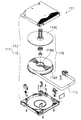
図8は、本発明の第2の実施の形態によるテープカートリッジ51の構成を示す分解斜視図である。テープカートリッジ51は、例えば合成樹脂材料でなる上シェル52と下シェル53とを互いに結合することにより形成されるカートリッジケース54に、テープ状記録媒体として磁気テープ55が巻装された単一のテープリール56を回転可能に収納して構成されている。
(Second Embodiment)
FIG. 8 is an exploded perspective view showing the configuration of the tape cartridge 51 according to the second embodiment of the present invention. The tape cartridge 51 is a single tape in which a magnetic tape 55 is wound as a tape-like recording medium on a cartridge case 54 formed by joining an upper shell 52 and a lower shell 53 made of, for example, a synthetic resin material. The reel 56 is configured to be rotatably accommodated.

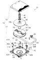
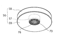
テープリール56は、磁気テープ55の巻芯部を構成するハブ57と、上フランジ58と、下フランジ59とでなる。テープリール56は、上フランジ58の中央部の凹所58a内に配置されたベアリング43を覆うベアリングキャップ42と上シェル52の内面中央部との間に設けられたリールスプリング41によって、下シェル53側に押し付けられている。磁気テープ55は、ハブ57に対して、磁性面を内向きにして巻装されている。なお、テープリール56の構成の詳細については後述する。   The tape reel 56 includes a hub 57 that constitutes a core portion of the magnetic tape 55, an upper flange 58, and a lower flange 59. The tape reel 56 is formed in a lower shell 53 by a reel spring 41 provided between a bearing cap 42 that covers a bearing 43 disposed in a recess 58 a in the central portion of the upper flange 58 and an inner surface central portion of the upper shell 52. It is pressed to the side. The magnetic tape 55 is wound around the hub 57 with the magnetic surface facing inward. Details of the configuration of the tape reel 56 will be described later.

テープカートリッジ51の非使用時においては、リールロックスプリング60A,60Bによって付勢された一対のリールロック部材61A,61Bにより、テープリール56が回転不可能とされている。リールロックスプリング60A,60B及びリールロック部材61A,61Bはそれぞれ、下シェル53の内面に立設された支持軸62A,62Bに回転可能に取り付けられている。   When the tape cartridge 51 is not used, the tape reel 56 cannot be rotated by the pair of reel lock members 61A and 61B biased by the reel lock springs 60A and 60B. The reel lock springs 60A and 60B and the reel lock members 61A and 61B are rotatably attached to support shafts 62A and 62B provided upright on the inner surface of the lower shell 53, respectively.

また、このテープカートリッジ51の非使用時において、磁気テープ55はテープリール56に完全に巻き取られた状態にある。磁気テープ55の繰出し端部には透明なリーダーテープ63が接合されている。リーダーテープ63の先端部は、上シェル52と下シェル53との結合時にカートリッジケース54の正面に形成されるテープ引出し用の開口部64をカートリッジケース54の内方側から閉塞するように配置されるリーダーブロック65の一側面に対し、クランパ66を介して接続されている。リーダーブロック65は、略コの字形状のリーダーブロックバネ67に弾性的に支持された状態で開口部64内方に位置決めされている。   When the tape cartridge 51 is not used, the magnetic tape 55 is completely wound on the tape reel 56. A transparent leader tape 63 is joined to the feeding end of the magnetic tape 55. The leading end portion of the leader tape 63 is disposed so as to close the tape drawing opening 64 formed on the front surface of the cartridge case 54 from the inner side of the cartridge case 54 when the upper shell 52 and the lower shell 53 are coupled. The reader block 65 is connected to one side surface via a clamper 66. The leader block 65 is positioned inside the opening 64 while being elastically supported by a substantially U-shaped leader block spring 67.

また、カートリッジテープ接触防止ピン68は、カートリッジケース54から引き出される磁気テープ55が開口部64の縁部に直接接触するのを防止するように、当該開口部64の縁部に直立状態で配置されている。これにより、磁気テープ55は、そのテープ幅より若干大きめの軸長を有するカートリッジテープ接触防止ピン68によるテープガイド作用を受け、開口部64の縁部における上シェル52と下シェル53との突合せ結合部への接触による損傷が防止される。   The cartridge tape contact prevention pin 68 is arranged in an upright state at the edge of the opening 64 so as to prevent the magnetic tape 55 drawn from the cartridge case 54 from coming into direct contact with the edge of the opening 64. ing. As a result, the magnetic tape 55 receives a tape guide action by the cartridge tape contact prevention pin 68 having an axial length slightly larger than the tape width, and the butt coupling between the upper shell 52 and the lower shell 53 at the edge of the opening 64. Damage due to contact with the parts is prevented.

なお、このテープカートリッジ51においては、磁気テープ20への誤記録、誤消去を防止するためのセイフティタブ69と、磁気テープ55に記録されている内容に関する情報を記録したメモリ基板70と、テープエンド検出用の透明な窓部材71A,71B等がそれぞれ設けられている。   In this tape cartridge 51, a safety tab 69 for preventing erroneous recording and erroneous erasure on the magnetic tape 20, a memory substrate 70 on which information relating to the contents recorded on the magnetic tape 55 is recorded, a tape end Transparent window members 71A, 71B and the like for detection are provided.

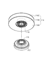
次に、テープリール56の詳細について図9〜図13を参照して説明する。   Next, details of the tape reel 56 will be described with reference to FIGS.

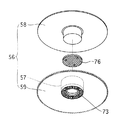
ここで、図9はテープリール56を下フランジ59側から見たときの斜視図、図10は同分解斜視図、図11はテープリール56の側断面図、図12はテープリール56の上フランジを取り外して見たときの要部平面図、図13はテープリール56の回転駆動時における要部断面図である。   9 is a perspective view when the tape reel 56 is viewed from the lower flange 59 side, FIG. 10 is an exploded perspective view thereof, FIG. 11 is a side sectional view of the tape reel 56, and FIG. 12 is an upper flange of the tape reel 56. FIG. 13 is a cross-sectional view of the main part when the tape reel 56 is driven to rotate.

上述のように、テープリール56は、ハブ57、上フランジ58及び下フランジ59で構成されている。これらハブ57、上フランジ58及び下フランジ59は、それぞれ、ポリカーボネート(PC)樹脂、ポリスチレン(PS)樹脂、ポリアセタール(POM)樹脂、アクリロニトリルスチロール(AS)樹脂等の合成樹脂材料で形成できるが、これ以外に、アルミニウムあるいはチタン、マグネシウム等の金属材料や、鉄あるいは磁性ステンレス鋼(SUS430等)といった磁性材料等で構成することもできる。   As described above, the tape reel 56 includes the hub 57, the upper flange 58, and the lower flange 59. The hub 57, the upper flange 58, and the lower flange 59 can be formed of a synthetic resin material such as polycarbonate (PC) resin, polystyrene (PS) resin, polyacetal (POM) resin, acrylonitrile styrene (AS) resin. In addition, it can be made of a metal material such as aluminum, titanium or magnesium, or a magnetic material such as iron or magnetic stainless steel (SUS430 or the like).

また、本実施の形態において、ハブ57は、下フランジ59とは一体的に形成され、上フランジ58とは、ハブ57の上端に形成された溶着リブ75を介しての超音波接合等により一体化されているが、勿論、これらを別部材で構成してもよい。特に、下フランジ59を磁性材料で形成することにより、後述するようにリール回転駆動軸より発生する磁界を遮蔽して磁気テープ55に対する磁気的な影響を回避することができる。この場合、下フランジ59は、金属材料等の薄板を円盤状に打抜き形成したり型成形で構成できる。また、上記磁性材料は、合成樹脂材料中に磁性金属フィラーを含有させた複合材料や、表面に磁性層を形成したものでもよい。   In the present embodiment, the hub 57 is formed integrally with the lower flange 59, and the upper flange 58 is integrated by ultrasonic bonding or the like via a welding rib 75 formed at the upper end of the hub 57. Of course, these may be constituted by separate members. In particular, by forming the lower flange 59 from a magnetic material, it is possible to shield a magnetic field generated from the reel rotation drive shaft and avoid magnetic influence on the magnetic tape 55 as will be described later. In this case, the lower flange 59 can be formed by stamping or forming a thin plate of a metal material or the like into a disk shape. The magnetic material may be a composite material in which a magnetic metal filler is contained in a synthetic resin material or a magnetic layer formed on the surface.

テープリール56の下面中央部には、記録再生装置側のリール回転駆動軸81の先端に放射状に形成された係合突起82と係合するチャッキングギヤ73が、駆動係合部として形成されている。チャッキングギヤ73は、ハブ57の底部外面側に形成されており、リール回転駆動軸81の回転駆動力がこれらチャッキングギヤ73と係合突起82との係合機構を介してテープリール56に伝達されるようになっている。   A chucking gear 73 that engages with engagement protrusions 82 formed radially at the tip of the reel rotation drive shaft 81 on the recording / reproducing apparatus side is formed as a drive engagement portion at the center of the lower surface of the tape reel 56. Yes. The chucking gear 73 is formed on the bottom outer surface side of the hub 57, and the rotational driving force of the reel rotation drive shaft 81 is applied to the tape reel 56 via the engagement mechanism between the chucking gear 73 and the engagement protrusion 82. It is to be transmitted.

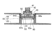
テープリール56とリール回転駆動軸81との密着性を高めるために、テープリール56には、リール回転駆動軸81に対して磁気吸着する磁性部材76が設けられている。この磁性部材76は、ハブ57に内装されている(図11)。リール回転駆動軸81の先端には、上記磁性部材76に磁気吸着力を発生させる永久磁石83が組み込まれている。   In order to improve the adhesion between the tape reel 56 and the reel rotation drive shaft 81, the tape reel 56 is provided with a magnetic member 76 that is magnetically attracted to the reel rotation drive shaft 81. The magnetic member 76 is built in the hub 57 (FIG. 11). A permanent magnet 83 for generating a magnetic attractive force on the magnetic member 76 is incorporated at the tip of the reel rotation drive shaft 81.

従って、テープリール56とリール回転駆動軸81とが精度良く係合し、係合後及び回転駆動中にあっては、テープリール56とリール回転駆動軸81との間が強固に密着して、自由に挿脱したり揺動することなくその密着状態が保持される。これにより、テープリール56とリール回転駆動軸81との間の軸心位置のバラツキや、テープリール56とリール回転駆動軸81との間の係合のバラツキ等に起因して発生するテープリール56の軸振れ、面振れ、周振れ等を防止して、磁気テープ55の安定した高速走行性を確保することができる共に、アクセス速度向上のため、テープリール56の更なる高速回転化にも十分に対応することが可能となる。   Therefore, the tape reel 56 and the reel rotation drive shaft 81 are engaged with each other with high accuracy, and the tape reel 56 and the reel rotation drive shaft 81 are in close contact with each other after the engagement and during the rotation drive. The close contact state is maintained without being freely inserted and removed or rocked. Accordingly, the tape reel 56 generated due to variations in the axial center position between the tape reel 56 and the reel rotation drive shaft 81, variations in engagement between the tape reel 56 and the reel rotation drive shaft 81, and the like. Shaft stability, surface runout, circumferential runout, etc. can be prevented to ensure stable high speed running of the magnetic tape 55, and the tape reel 56 can be rotated at a higher speed to improve access speed. It becomes possible to cope with.

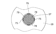
図11及び図12に示したように、磁性部材76は、ハブ57に内装されている。ハブ57は筒状を有し、ハブ57の内部には、磁性部材76を収納する収納部77が形成されている。収納部77の底部77a中央には、収納部77の内方に向かって円錐状に延在する環状の第1リブ79Aと、収納部77の外方(ハブ57の下面)に向かって直線状に延在する円環状の第2リブ79Bとが、互いに連接されてなる開口部79が形成されている。磁性部材76は、第1リブ79Aの上端と、収納部77の底部周縁に突設された段部80を介して、収納部77の底部に支持されている。   As shown in FIGS. 11 and 12, the magnetic member 76 is built in the hub 57. The hub 57 has a cylindrical shape, and a housing 77 for housing the magnetic member 76 is formed inside the hub 57. In the center of the bottom 77a of the storage portion 77, an annular first rib 79A that extends conically toward the inside of the storage portion 77, and a straight line toward the outside of the storage portion 77 (the lower surface of the hub 57). An opening 79 is formed in which an annular second rib 79 </ b> B extending in the direction is connected to each other. The magnetic member 76 is supported on the bottom portion of the storage portion 77 via the upper end of the first rib 79 </ b> A and a stepped portion 80 protruding from the periphery of the bottom portion of the storage portion 77.

磁性部材76は、ハブ57の内径よりも小径な円盤状に形成されている(図12)。特に本実施の形態では、ハブ57の内径の大きさに近接する大きさに磁性部材76の外径が設定されている。これにより、テープリール56の回転時における遠心力及びイナーシャの影響を小さくすることが可能となるので、これに起因するテープリール56の回転振動を低く抑えることが可能となり、高速信頼性を高くすることができる。また、磁性部材76とリール回転駆動軸81の永久磁石83との間に形成される磁界を、ハブ57に巻装されている磁気テープ55から遠ざけることができるので、磁気テープ55が受ける磁気的影響を抑止できる。   The magnetic member 76 is formed in a disk shape smaller in diameter than the inner diameter of the hub 57 (FIG. 12). Particularly in the present embodiment, the outer diameter of the magnetic member 76 is set to a size close to the size of the inner diameter of the hub 57. As a result, it becomes possible to reduce the influence of centrifugal force and inertia during rotation of the tape reel 56, so that the rotational vibration of the tape reel 56 caused by this can be kept low, and high speed reliability is increased. be able to. Further, since the magnetic field formed between the magnetic member 76 and the permanent magnet 83 of the reel rotation drive shaft 81 can be moved away from the magnetic tape 55 wound around the hub 57, the magnetic force received by the magnetic tape 55 is reduced. The influence can be suppressed.

磁性部材76は、鉄や磁性ステンレス鋼(例えばSUS430)、珪素鋼板、パーマロイ等の軟磁気特性を有する強磁性材料で形成され、打抜きプレス等の機械加工により容易に製造できる。また、防錆等の特殊な表面処理は必要に応じて省略でき、厳しい寸法精度も必要とされないので、低コストに製造できる。更に、磁性部材76の面内中央部に位置決めのための加工を必要としないので、磁性部材76の中央部に出現する強力な磁気吸着力を有効に活用することが可能となり、高速走行時におけるテープリール56とリール回転駆動軸81との密着性を高めて磁気テープ55の走行安定性の向上を図ることができる。   The magnetic member 76 is formed of a ferromagnetic material having soft magnetic properties such as iron, magnetic stainless steel (for example, SUS430), silicon steel plate, and permalloy, and can be easily manufactured by machining such as a punching press. Further, special surface treatment such as rust prevention can be omitted as necessary, and strict dimensional accuracy is not required, so that it can be manufactured at low cost. Furthermore, since no positioning process is required at the central portion of the magnetic member 76, it is possible to effectively utilize the strong magnetic attractive force that appears at the central portion of the magnetic member 76, and during high-speed traveling. It is possible to improve the running stability of the magnetic tape 55 by improving the adhesion between the tape reel 56 and the reel rotation drive shaft 81.

なお、磁性部材76は円盤状に限らず、多角形状でもよい。また、磁性部材76は板状に限らず、例えばブロック状のものも適用可能であるが、テープリール56の安定した回転姿勢を確保するために、テープリール56の重心位置はなるべく低くなるように構成されているのが好ましい。   The magnetic member 76 is not limited to a disk shape, and may be a polygonal shape. In addition, the magnetic member 76 is not limited to a plate shape, and a block shape, for example, can be applied. However, in order to ensure a stable rotation posture of the tape reel 56, the center of gravity of the tape reel 56 is made as low as possible. Preferably, it is configured.

磁性部材76は、図11に示すように、収納部77の底部77aにかしめ固定することができる。この場合、収納部77の底部77aに、かしめ固定用の複数本の突起78を立設し、これに対応して、磁性部材76には、突起78が挿通される孔76aを貫通形成しておく。かしめ用の突起78は、テープリール56の回転軸の軸心を中心とする同一円周上に配置形成するようにし、これによりテープリール56の回転時における動的安定性(ダイナミックバランス)を確保して、高速信頼性を確保する。そして、磁性部材76を収納部77に収納する際、孔76aに突起78を挿通させ、磁性部材76の上面から突出した突起78の先端に例えば超音波振動を付与して溶融拡径させることにより、磁性部材76を収納部底部77aへ固着できる。   As shown in FIG. 11, the magnetic member 76 can be caulked and fixed to the bottom 77 a of the storage portion 77. In this case, a plurality of caulking fixing projections 78 are erected on the bottom 77 a of the storage portion 77, and correspondingly, the magnetic member 76 has a hole 76 a through which the projection 78 is inserted. deep. The caulking projections 78 are arranged and formed on the same circumference centered on the axis of the rotation axis of the tape reel 56, thereby ensuring dynamic stability (dynamic balance) when the tape reel 56 rotates. And ensure high speed reliability. Then, when the magnetic member 76 is stored in the storage portion 77, the protrusion 78 is inserted into the hole 76a, and, for example, ultrasonic vibration is applied to the tip of the protrusion 78 protruding from the upper surface of the magnetic member 76 to melt and expand the diameter. The magnetic member 76 can be fixed to the storage portion bottom 77a.

このように、磁性部材76をハブ57の内部の収納部77に内装させる構成とすることにより、ハブ57に対する磁性部材76の位置決め保持が容易となり、従来のように磁性部材の中心部に開口を形成する必要もない。従って、最も強く磁力が出現する磁性部材76の中心部をリール回転駆動軸81との主要磁気吸着部として構成できるので、テープリール56とリール回転駆動軸81との間の強固な密着状態を確保することができる。特に本実施の形態では、磁性部材76の中心部とリール回転駆動軸81の永久磁石83とが、テープリール56の開口部79を介して直接対峙する構成であるので、両者間のスペーシングロスが低減されて磁気吸着力の向上が図られる。   As described above, by arranging the magnetic member 76 in the housing portion 77 inside the hub 57, the positioning and holding of the magnetic member 76 with respect to the hub 57 is facilitated, and an opening is formed in the central portion of the magnetic member as in the prior art. There is no need to form. Accordingly, since the central portion of the magnetic member 76 where the magnetic force appears most strongly can be configured as a main magnetic attracting portion with the reel rotation drive shaft 81, a strong contact state between the tape reel 56 and the reel rotation drive shaft 81 is ensured. can do. In particular, in the present embodiment, since the central portion of the magnetic member 76 and the permanent magnet 83 of the reel rotation drive shaft 81 directly face each other through the opening 79 of the tape reel 56, the spacing loss between them Is reduced and the magnetic attractive force is improved.

一方、リール回転駆動軸81の先端中心部には、図13に示すように、永久磁石83を内蔵し開口部79に嵌合する突出部84と、この突出部84の径外方側に形成されテープリール56下面の第2リブ79Bが係合する環状溝85とが形成されている。なお、第2リブ79Bは、本発明の「円環部」に対応している。   On the other hand, as shown in FIG. 13, at the center of the tip end of the reel rotation drive shaft 81, there is a protrusion 84 with a built-in permanent magnet 83 fitted into the opening 79, and a radially outward side of the protrusion 84. An annular groove 85 that engages with the second rib 79B on the lower surface of the tape reel 56 is formed. The second rib 79B corresponds to the “annular portion” of the present invention.

突出部84の上面は略球面状とされることにより、第2リブ79Bによるガイド作用で開口部79内に進入し易くなっている。なお、この突出部84の断面形状を、第1,第2リブ79A,79Bの内面で区画される開口部79内部の断面形状と同等に形成することも勿論可能である。   Since the upper surface of the protrusion 84 has a substantially spherical shape, it can easily enter the opening 79 by the guide action of the second rib 79B. Of course, the cross-sectional shape of the projecting portion 84 can be formed to be equal to the cross-sectional shape inside the opening 79 defined by the inner surfaces of the first and second ribs 79A and 79B.

以上のように構成される本実施の形態のテープカートリッジ51においては、記録再生装置へ挿着されると、リールロック部材61A,61Bによるテープリール56の回転規制が解除されると共に、リール回転駆動軸81がチャッキングギヤ73に係合する。そして、リーダーブロック65がローディング機構により引き出され、テープリール56の回転による磁気テープ55の送り動作あるいは巻き戻し動作が行われる。   In the tape cartridge 51 of the present embodiment configured as described above, when the tape cartridge 56 is inserted into the recording / reproducing apparatus, the rotation restriction of the tape reel 56 by the reel lock members 61A and 61B is released, and the reel rotation drive is performed. The shaft 81 engages with the chucking gear 73. Then, the leader block 65 is pulled out by the loading mechanism, and the feeding operation or the rewinding operation of the magnetic tape 55 by the rotation of the tape reel 56 is performed.

本実施の形態によれば、テープリール56の回転駆動時、突出部84の上端に埋設させた永久磁石83が、ハブ57の収納部77に内装され開口部79を介して露出する磁性部材76の下面中央部に対向し、互いに磁気吸着される。これにより、テープリール56とリール回転駆動軸81との間の密着力が向上し、高速回転駆動時におけるテープリール56の浮上、揺動を回避して安定した回転姿勢を保持でき、磁気テープ55の高速走行時の安定性を向上させることができる。   According to the present embodiment, when the tape reel 56 is driven to rotate, the permanent magnet 83 embedded in the upper end of the protrusion 84 is housed in the housing 77 of the hub 57 and exposed through the opening 79. Are opposed to each other and are magnetically attracted to each other. As a result, the adhesive force between the tape reel 56 and the reel rotation drive shaft 81 is improved, and the stable rotation posture can be maintained by avoiding the floating and swinging of the tape reel 56 during the high-speed rotation drive. The stability at the time of high speed driving can be improved.

また、環状溝85には開口部79周縁の第2リブ79Bが係合し、これにおりリール回転駆動軸81との高精度なチャッキング係合が可能となり、振れの少ない安定した回転姿勢で回転駆動力がテープリール56に伝達される。   In addition, the second rib 79B on the periphery of the opening 79 is engaged with the annular groove 85, thereby enabling high-accuracy chucking engagement with the reel rotation drive shaft 81, and with a stable rotation posture with little swing. A rotational driving force is transmitted to the tape reel 56.

更に、リール回転駆動軸81と磁気吸着する磁性部材76は、ハブ57の収納部77に内装された構成であるので、磁性部材76がテープリール56から分離、脱落するといった懸念を解消できる。また、外部からの衝撃を直接磁性部材76が受けない構成なので、磁性部材76の錆、傷、摩耗等に対する考慮も特に必要なく、磁性部材76を安価に、生産性高く、作製できるようになる。   Further, since the magnetic member 76 that is magnetically attracted to the reel rotation drive shaft 81 is built in the housing portion 77 of the hub 57, the concern that the magnetic member 76 is separated from the tape reel 56 and dropped off can be solved. In addition, since the magnetic member 76 is not directly subjected to external impact, there is no particular need to consider rust, scratches, wear, etc. of the magnetic member 76, and the magnetic member 76 can be manufactured at low cost and with high productivity. .

(第3の実施の形態)
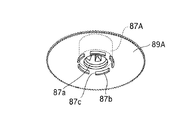
図14及び図15は、本発明の第3の実施の形態を示している。本実施の形態のテープリール86は、上述の各実施の形態と同様、テープ巻芯部を構成するハブ87、上フランジ88及び下フランジ59を備えている。本実施の形態のテープリール86は、後述するように、ハブ87の内周部に駆動係合部90を形成した、いわゆる側面チャッキング構造が採用されている。このテープリール86は、上述の2リールタイプのテープカートリッジ1及び1リールタイプのテープカートリッジ51の何れにも適用可能である。
(Third embodiment)
14 and 15 show a third embodiment of the present invention. The tape reel 86 of the present embodiment includes a hub 87, an upper flange 88, and a lower flange 59 that constitute a tape core portion, as in the above-described embodiments. As will be described later, the tape reel 86 of the present embodiment employs a so-called side chucking structure in which a drive engagement portion 90 is formed on the inner peripheral portion of the hub 87. This tape reel 86 can be applied to both the above-described two-reel type tape cartridge 1 and one-reel type tape cartridge 51.

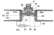
本実施の形態のテープリール86においては、リール回転駆動軸94と磁気吸着する円盤状の磁性部材91の下面周囲が、ハブ87の内部に形成された収納部92の底部92aに支持されている。即ち、収納部92の底部92aには開口部93が形成されており、この開口部93を介して、円盤状の磁性部材91の一部がテープリール86の下面から露出している。   In the tape reel 86 of the present embodiment, the periphery of the lower surface of the disk-shaped magnetic member 91 that is magnetically attracted to the reel rotation drive shaft 94 is supported by the bottom portion 92 a of the storage portion 92 formed inside the hub 87. . That is, an opening 93 is formed in the bottom 92 a of the storage portion 92, and a part of the disk-shaped magnetic member 91 is exposed from the lower surface of the tape reel 86 through the opening 93.

磁性部材91の上面周縁部は、ハブ87の上端に接合される上フランジ88の凹所88a下面から垂設された位置決め用のリブ94Aの下端と対向しており、これにより磁性部材91の横臥姿勢が保持されている。即ち、リブ94Aは、本発明の「姿勢保持体」をも兼ねた構成となっている。   The peripheral edge of the upper surface of the magnetic member 91 is opposed to the lower end of a positioning rib 94A suspended from the lower surface of the recess 88a of the upper flange 88 joined to the upper end of the hub 87. Posture is maintained. That is, the rib 94A also serves as the “posture holder” of the present invention.

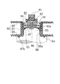
ハブ87の内周部には、リール回転駆動軸94に係合するチャッキングギヤ90が径内方へ突出形成されており、リール回転駆動軸94上端の突出部95外周面に形成されている係合突起と係合して、テープリール86へ回転駆動力が伝達されるようになっている。突出部95の上端には、磁性部材91に磁気吸着力を発生させる永久磁石96が埋設されており、テープリール86の駆動回転時、磁性部材91の中心部と近接または接触して、テープリール86とリール回転駆動軸94との密着力が高められている。   A chucking gear 90 that engages with the reel rotation drive shaft 94 is formed on the inner peripheral portion of the hub 87 so as to protrude radially inward, and is formed on the outer peripheral surface of the protrusion 95 at the upper end of the reel rotation drive shaft 94. The rotational driving force is transmitted to the tape reel 86 by engaging with the engaging protrusion. A permanent magnet 96 that generates a magnetic attraction force on the magnetic member 91 is embedded at the upper end of the protruding portion 95. When the tape reel 86 is driven to rotate, the permanent magnet 96 approaches or comes into contact with the center portion of the magnetic member 91. Adhesion between 86 and the reel rotation drive shaft 94 is enhanced.

以上のように構成される本実施の形態のテープリール86によっても、上述の各実施の形態と同様な効果を得ることができ、テープリール86とリール回転駆動軸94との密着力を高めて、テープリール86の回転姿勢の安定性を高め、磁気テープの安定した高速走行性が得られるようになっている。   Also with the tape reel 86 of the present embodiment configured as described above, the same effects as those of the above-described embodiments can be obtained, and the adhesion between the tape reel 86 and the reel rotation drive shaft 94 is increased. Further, the stability of the rotation posture of the tape reel 86 is improved, and the stable high-speed running property of the magnetic tape can be obtained.

なお、本実施の形態において、テープリール86とリール回転駆動軸94との間の適正な係合関係を得るために、ハブ87の内周部下端に「円環部」として環状の凹所87a(図14)を形成し、これにリール回転駆動軸94の突出部95の基端部周縁に形成した環状段部95a(図15)を係合させるようにしている。   In this embodiment, in order to obtain an appropriate engagement relationship between the tape reel 86 and the reel rotation drive shaft 94, an annular recess 87a is formed as an “annular portion” at the lower end of the inner peripheral portion of the hub 87. (FIG. 14) is formed, and an annular step portion 95a (FIG. 15) formed on the periphery of the base end portion of the protruding portion 95 of the reel rotation drive shaft 94 is engaged therewith.

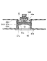
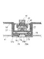
図16は、上述のテープリール86の構成の一変形例を示し、図示するテープリール86Aにおいては、そのハブ87Aの内部に形成されている収納部92の底部92aに開口部を有しておらず、上述の第1の実施の形態と同様、磁性部材91を外部へ露出しない構成とされている。この構成において、磁性部材91の上面は、上フランジ88Aの凹所88a下面に形成した姿勢保持用のリブ94Bの下端と対向されており、このリブ94Bによって磁性部材91の横臥姿勢が保持されている。   FIG. 16 shows a modification of the configuration of the tape reel 86 described above. The illustrated tape reel 86A has an opening at the bottom 92a of the storage portion 92 formed inside the hub 87A. In the same manner as in the first embodiment, the magnetic member 91 is not exposed to the outside. In this configuration, the upper surface of the magnetic member 91 is opposed to the lower end of the posture holding rib 94B formed on the lower surface of the recess 88a of the upper flange 88A, and the recumbent posture of the magnetic member 91 is held by the rib 94B. Yes.

このような構成のテープリール86Aにおいても上述と同様な効果を得ることができ、テープリール86Aとリール回転駆動軸との間の軸心位置のバラツキや、テープリール86Aとリール回転駆動軸との間の係合のバラツキ等に起因して発生するテープリール86Aの軸振れ、面振れ、周振れ等を防止して、磁気テープの安定した高速走行性を確保することができる共に、アクセス速度向上のため、テープリール86Aの更なる高速回転化にも十分に対応することが可能となる。   In the tape reel 86A having such a configuration, the same effect as described above can be obtained, and variations in the axial center position between the tape reel 86A and the reel rotation drive shaft, and between the tape reel 86A and the reel rotation drive shaft can be obtained. Prevents axial reeling, surface runout, circumferential runout, etc. of the tape reel 86A caused by variations in the engagement between them, ensuring stable high-speed running performance of the magnetic tape and improving access speed Therefore, it is possible to sufficiently cope with the further high speed rotation of the tape reel 86A.

一方、本実施の形態において、下フランジ89Aの下面には、リール回転駆動軸の上端面に係合する環状リブ87bが形成されており、上述の第2の実施の形態において説明した環状の凹所87aと協働して、テープリール86Aとリール回転駆動軸との係合のガイド作用を果たし、テープリール86Aの回転姿勢の適正化を図る構成となっている。   On the other hand, in the present embodiment, an annular rib 87b that engages with the upper end surface of the reel rotation drive shaft is formed on the lower surface of the lower flange 89A, and the annular recess described in the second embodiment described above. In cooperation with the location 87a, a guide action for engaging the tape reel 86A with the reel rotation drive shaft is achieved, and the rotation posture of the tape reel 86A is optimized.

なお、上記リブ87bは環状である場合に限らず、例えば図17に示すように、円周に沿って切欠き87cが部分的に形成されるように間欠形成すれば、リール回転駆動軸との係合時に、切欠き87cを介して環状リブ87bの内方側から外方側への空気の移動が容易となり、ハブの内周部へリール回転駆動軸を円滑に挿入することが可能となる。   The rib 87b is not limited to an annular shape. For example, as shown in FIG. 17, if the rib 87b is intermittently formed so that a notch 87c is partially formed along the circumference, the rib 87b At the time of engagement, the movement of air from the inner side to the outer side of the annular rib 87b is facilitated through the notch 87c, and the reel rotation drive shaft can be smoothly inserted into the inner peripheral portion of the hub. .

以上、本発明の各実施の形態について説明したが、勿論、本発明はこれらに限定されることなく、本発明の技術的思想に基づいて種々の変形が可能である。   As mentioned above, although each embodiment of this invention was described, of course, this invention is not limited to these, A various deformation | transformation is possible based on the technical idea of this invention.

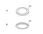
例えば以上の各実施の形態では、リール回転駆動軸と磁気吸着する磁性部材を円盤状に形成したが、これに限らず、例えば図18A,Bに示すように、中央部をドーム状に湾曲形成した磁性部材97も、本発明は適用可能である。ここで、図18Aは磁性部材97を上方側から見たときの斜視図、図18Bは磁性部材97を下方側から見たときの斜視図である。この磁性部材97のテープリールへの適用例を図19に示す。なお、図において図15に対応する部分については同一の符号を付し、その詳細な説明は省略する。   For example, in each of the above-described embodiments, the reel rotation drive shaft and the magnetic member that magnetically attracts are formed in a disk shape. However, the present invention is not limited to this. For example, as shown in FIGS. The present invention is also applicable to the magnetic member 97. Here, FIG. 18A is a perspective view when the magnetic member 97 is viewed from above, and FIG. 18B is a perspective view when the magnetic member 97 is viewed from below. An example of application of the magnetic member 97 to a tape reel is shown in FIG. In the figure, portions corresponding to those in FIG. 15 are denoted by the same reference numerals, and detailed description thereof is omitted.

このように、リール回転駆動軸94の突出部95上端を覆うような、上面が凸なるドーム状に磁性部材97を形成することによって、突出部95の頂部に配置された永久磁石96との間で発生する磁力を磁性部材97の中心部に集中させることが可能となる。これにより、テープリール86とリール回転駆動軸94の密着性をより向上させることができると共に、ハブ87に巻装されている磁気テープに対するテープリール86とリール回転駆動軸94との間の吸着磁界からの保護効果をも高めることができる。   As described above, the magnetic member 97 is formed in a dome shape having a convex upper surface so as to cover the upper end of the protruding portion 95 of the reel rotation drive shaft 94, so that the permanent magnet 96 disposed on the top portion of the protruding portion 95 is formed. It is possible to concentrate the magnetic force generated at the center of the magnetic member 97. As a result, the adhesion between the tape reel 86 and the reel rotation drive shaft 94 can be further improved, and the magnetic field attracted between the tape reel 86 and the reel rotation drive shaft 94 with respect to the magnetic tape wound around the hub 87. The protective effect from can also be enhanced.

また、以上の第1の実施の形態では、いわゆる2リールタイプのテープカートリッジにおいて、リール回転駆動軸と係合するチャッキングギヤをテープリールのハブ底部下面に形成した例について説明したが、勿論、これに限らず、例えば上述の第3の実施の形態のように、ハブの内周部にチャッキングギヤを形成した側面チャッキング構造のテープリールを適用することも可能である。   In the first embodiment described above, in the so-called two-reel type tape cartridge, an example in which the chucking gear that engages with the reel rotation drive shaft is formed on the bottom surface of the hub bottom of the tape reel has been described. For example, a tape reel having a side chucking structure in which a chucking gear is formed on the inner peripheral portion of the hub can be applied as in the above-described third embodiment.

また、上述の第2の実施の形態及び第3の実施の形態に示したテープリール対して、図7を参照して説明したように、下フランジ41を磁性金属板で形成する例も適用可能である。第2の実施の形態に磁性金属製の下フランジ41を適用した例を図20に示す。図において、上述の第2の実施の形態と対応する部分については同一の符号を付し、その詳細な説明は省略する。本例においても、ハブ57の下端をかしめ溶融させた溶着部57pによって、ハブ57と下フランジ41の一体化が図られている。   Further, as described with reference to FIG. 7, the example in which the lower flange 41 is formed of a magnetic metal plate can be applied to the tape reels shown in the second and third embodiments. It is. An example in which a magnetic metal lower flange 41 is applied to the second embodiment is shown in FIG. In the figure, portions corresponding to those of the second embodiment described above are denoted by the same reference numerals, and detailed description thereof is omitted. Also in this example, the hub 57 and the lower flange 41 are integrated by the welded portion 57p in which the lower end of the hub 57 is caulked and melted.

本発明の第1の実施の形態によるテープカートリッジ1の構成を示す分解斜視図である。It is a disassembled perspective view which shows the structure of the tape cartridge 1 by the 1st Embodiment of this invention. 図1のテープカートリッジに適用されるテープリールの上フランジを取り外して見たときの斜視図である。It is a perspective view when the upper flange of the tape reel applied to the tape cartridge of FIG. 1 is removed and viewed. 同テープリール6の下フランジ側から見たときの斜視図である。FIG. 3 is a perspective view when viewed from the lower flange side of the tape reel 6. 同テープリール6の側断面図である。3 is a side sectional view of the tape reel 6. FIG. 同テープリールの上フランジを取り外して見たときの平面図である。It is a top view when the upper flange of the tape reel is removed and viewed. 同テープリールの構成の一変形例を示す側断面図である。It is a sectional side view which shows the modification of a structure of the same tape reel. 同テープリールの構成の他の変形例を示す側断面図である。It is side sectional drawing which shows the other modification of the structure of the same tape reel. 本発明の第2の実施の形態によるテープカートリッジ51の構成を示す分解斜視図である。It is a disassembled perspective view which shows the structure of the tape cartridge 51 by the 2nd Embodiment of this invention. 図8のテープカートリッジに適用されるテープリール56の下フランジ側から見たときの斜視図である。It is a perspective view when it sees from the lower flange side of the tape reel 56 applied to the tape cartridge of FIG. テープリール56の分解斜視図である。2 is an exploded perspective view of a tape reel 56. FIG. テープリール56の側断面図である。3 is a side sectional view of the tape reel 56. FIG. 同テープリールの上フランジを取り外して見たときの平面図である。It is a top view when the upper flange of the tape reel is removed and viewed. テープリール56の回転駆動時における側断面図である。FIG. 6 is a side sectional view of the tape reel 56 when it is rotationally driven. 本発明の第3の実施の形態によるテープリール86の構成を示す側断面図である。It is a sectional side view which shows the structure of the tape reel 86 by the 3rd Embodiment of this invention. テープリールの回転駆動時における側断面図である。It is a sectional side view at the time of the rotational drive of a tape reel. 同テープリールの構成の一変形例を示す側断面図である。It is a sectional side view which shows the modification of a structure of the same tape reel. 同テープリールの構成の他の変形例を示す斜視図である。It is a perspective view which shows the other modification of a structure of the same tape reel. 磁性部材の構成の変形例を示す斜視図である。It is a perspective view which shows the modification of a structure of a magnetic member. 図18に示した磁性部材が適用されたテープリールの回転駆動時における側断面図である。It is a sectional side view at the time of the rotational drive of the tape reel to which the magnetic member shown in FIG. 18 was applied. 第2の実施の形態におけるテープリールの構成の一変形例を示す側断面図である。It is a sectional side view which shows one modification of the structure of the tape reel in 2nd Embodiment. 従来のテープカートリッジの第1の構成例を示す分解斜視図である。It is a disassembled perspective view which shows the 1st structural example of the conventional tape cartridge. 従来のテープカートリッジの第2の構成例を示す分解斜視図である。It is a disassembled perspective view which shows the 2nd structural example of the conventional tape cartridge. 従来の第1の構成例におけるテープリール及びこれを回転駆動するリール回転駆動軸との関係を示す斜視図である。It is a perspective view which shows the relationship between the tape reel in the conventional 1st structural example, and the reel rotation drive shaft which rotationally drives this. 従来の第2の構成例におけるテープリール及びこれを回転駆動するリール回転駆動軸との関係を示す斜視図である。It is a perspective view which shows the relationship between the tape reel in the conventional 2nd structural example, and the reel rotational drive shaft which rotationally drives this. 磁性金属プレートをハブの下面に外装した従来のテープリールの裏面図である。It is a back view of the conventional tape reel which coat | covered the magnetic metal plate on the lower surface of the hub.

符号の説明Explanation of symbols

1,51…テープカートリッジ、2,52…上シェル、3,53…下シェル、4,54…カートリッジケース、5,55…磁気テープ、6,56,86,86A…テープリール、13,58,88,88A…上フランジ、14,59,89,89A…下フランジ、15,57,87,87A…ハブ、31,73,90…チャッキングギヤ(駆動係合部)、35,76,91,97…磁性部材、36,77,92…収納部、81,94…リール回転駆動軸、79,93…開口部、83,96…永久磁石。   DESCRIPTION OF SYMBOLS 1,51 ... Tape cartridge, 2,52 ... Upper shell, 3,53 ... Lower shell, 4,54 ... Cartridge case, 5,55 ... Magnetic tape, 6, 56, 86, 86A ... Tape reel, 13, 58, 88, 88A ... upper flange, 14, 59, 89, 89A ... lower flange, 15, 57, 87, 87A ... hub, 31, 73, 90 ... chucking gear (drive engagement portion), 35, 76, 91, 97: Magnetic member, 36, 77, 92: Storage portion, 81, 94: Reel rotation drive shaft, 79, 93: Opening portion, 83, 96: Permanent magnet.

Claims (11)

カートリッジケースと、
磁気テープが巻装され前記カートリッジケースに回転可能に収容されたハブと、
記録再生装置の回転駆動軸に磁気吸着する磁性部材と、
前記ハブの内部に形成され前記磁性部材が収納される収納部とを備えた
ことを特徴とするテープカートリッジ。
A cartridge case,
A hub wound with a magnetic tape and rotatably accommodated in the cartridge case;
A magnetic member that is magnetically attracted to the rotational drive shaft of the recording / reproducing apparatus;
A tape cartridge comprising: a housing portion formed inside the hub and housing the magnetic member.
前記ハブの底部又は内周部には、前記回転駆動軸と係合される駆動係合部が設けられている
ことを特徴とする請求項1に記載のテープカートリッジ。
The tape cartridge according to claim 1, wherein a drive engagement portion that is engaged with the rotation drive shaft is provided at a bottom portion or an inner peripheral portion of the hub.
前記磁性部材は、前記ハブの外径よりも小径の円盤状である
ことを特徴とする請求項1に記載のテープカートリッジ。
The tape cartridge according to claim 1, wherein the magnetic member has a disk shape having a smaller diameter than the outer diameter of the hub.
前記磁性部材は、前記収納部の底部で支持されている
ことを特徴とする請求項1に記載のテープカートリッジ。
The tape cartridge according to claim 1, wherein the magnetic member is supported by a bottom portion of the storage portion.
前記磁性部材は、前記収納部の底部にかしめ固定されている
ことを特徴とする請求項4に記載のテープカートリッジ。
The tape cartridge according to claim 4, wherein the magnetic member is fixed by caulking to a bottom portion of the storage portion.
前記収納部には、前記底部に載置されている磁性部材の上面と対向する姿勢保持体が挿入されている
ことを特徴とする請求項4に記載のテープカートリッジ。
The tape cartridge according to claim 4, wherein a posture holding body facing the upper surface of the magnetic member placed on the bottom portion is inserted into the storage portion.
前記ハブの少なくとも下端周縁には、径外方へ延在するフランジが設けられており、前記フランジが磁性材料を含んでなる
ことを特徴とする請求項1に記載のテープカートリッジ。
The tape cartridge according to claim 1, wherein a flange extending radially outward is provided at least at a peripheral edge of the lower end of the hub, and the flange includes a magnetic material.
前記収納部の底部中央には、前記磁性部材を部分的に露出させる開口部が形成されている
ことを特徴とする請求項4に記載のテープカートリッジ。
The tape cartridge according to claim 4, wherein an opening that partially exposes the magnetic member is formed in the center of the bottom of the storage portion.
前記ハブの底部又は内周部には、前記回転駆動軸と係合される円環部が設けられている
ことを特徴とする請求項2に記載のテープカートリッジ。
The tape cartridge according to claim 2, wherein an annular portion that is engaged with the rotation drive shaft is provided at a bottom portion or an inner peripheral portion of the hub.
前記円環部は、前記回転駆動軸側に突出する円環状のリブでなると共に、その一部には切欠きが形成されている
ことを特徴とする請求項9に記載のテープカートリッジ。
10. The tape cartridge according to claim 9, wherein the annular portion is formed of an annular rib protruding toward the rotation drive shaft, and a notch is formed in a part thereof.
前記磁性部材は、ドーム状に形成されている
ことを特徴とする請求項1に記載のテープカートリッジ。
The tape cartridge according to claim 1, wherein the magnetic member is formed in a dome shape.
JP2004105421A 2004-03-31 2004-03-31 Tape cartridge Pending JP2005293691A (en)

Priority Applications (1)

Application Number Priority Date Filing Date Title
JP2004105421A JP2005293691A (en) 2004-03-31 2004-03-31 Tape cartridge

Applications Claiming Priority (1)

Application Number Priority Date Filing Date Title
JP2004105421A JP2005293691A (en) 2004-03-31 2004-03-31 Tape cartridge

Publications (1)

Publication Number Publication Date
JP2005293691A true JP2005293691A (en) 2005-10-20

Family

ID=35326465

Family Applications (1)

Application Number Title Priority Date Filing Date
JP2004105421A Pending JP2005293691A (en) 2004-03-31 2004-03-31 Tape cartridge

Country Status (1)

Country Link
JP (1) JP2005293691A (en)

Cited By (3)

* Cited by examiner, † Cited by third party
Publication number Priority date Publication date Assignee Title
JP2008041129A (en) * 2006-08-02 2008-02-21 Hitachi Maxell Ltd Tape cartridge and tape reel drive structure and tape drive
JP2008041221A (en) * 2006-08-10 2008-02-21 Tdk Corp Information medium
US8564907B2 (en) 2007-05-01 2013-10-22 Sony Corporation Position determining member to align a magnetic tape cartridge in a magnetic recording and reproducing apparatus

Cited By (4)

* Cited by examiner, † Cited by third party
Publication number Priority date Publication date Assignee Title
JP2008041129A (en) * 2006-08-02 2008-02-21 Hitachi Maxell Ltd Tape cartridge and tape reel drive structure and tape drive
JP2008041221A (en) * 2006-08-10 2008-02-21 Tdk Corp Information medium
US7775472B2 (en) 2006-08-10 2010-08-17 Tdk Corporation Information medium
US8564907B2 (en) 2007-05-01 2013-10-22 Sony Corporation Position determining member to align a magnetic tape cartridge in a magnetic recording and reproducing apparatus

Similar Documents

Publication Publication Date Title
JP4782026B2 (en) Tape reel manufacturing method and machine reel manufacturing method
JP4805232B2 (en) reel
JP3978787B2 (en) Disk storage
JP2009211743A (en) Tape reel, tape cartridge, and tape drive system
JP2005293691A (en) Tape cartridge
JP2007299437A (en) Reel and recording tape cartridge
JP4315762B2 (en) Recording tape cartridge
US11217278B2 (en) Tape cartridge including reel lock member
JP4846749B2 (en) Recording tape cartridge
JP4102849B1 (en) Recording tape cartridge
JP2005317153A (en) Tape cartridge
JPH1196717A (en) Magnetic tape cartridge
JP3839741B2 (en) Recording tape cartridge
JP2009076160A (en) Magnetic tape cartridge
JP4141163B2 (en) Recording tape cartridge
JP2005050486A (en) Recording tape cartridge
JP4091162B2 (en) Magnetic tape cartridge
JP4790503B2 (en) Reel and recording tape cartridge
JP2016062633A (en) Metal plate and recording tape cartridge
JP2000048529A (en) Magnetic tape cartridge
JPH11213614A (en) Magnetic tape cartridge
JP2006053963A (en) Tape cartridge
JP2000067560A (en) Magnetic tape cartridge
JP2003228953A (en) Recording tape cartridge
JPH11213612A (en) Magnetic tape cartridge