JP2005293680A - Content cue position control method, content cue position control device and content cue position control program - Google Patents
Content cue position control method, content cue position control device and content cue position control program Download PDFInfo
- Publication number
- JP2005293680A JP2005293680A JP2004104567A JP2004104567A JP2005293680A JP 2005293680 A JP2005293680 A JP 2005293680A JP 2004104567 A JP2004104567 A JP 2004104567A JP 2004104567 A JP2004104567 A JP 2004104567A JP 2005293680 A JP2005293680 A JP 2005293680A
- Authority
- JP
- Japan
- Prior art keywords
- content
- position control
- time stamp
- search
- speed
- Prior art date
- Legal status (The legal status is an assumption and is not a legal conclusion. Google has not performed a legal analysis and makes no representation as to the accuracy of the status listed.)
- Granted
Links
- 238000000034 method Methods 0.000 title claims description 53
- 238000001514 detection method Methods 0.000 claims description 28
- 238000010586 diagram Methods 0.000 description 2
- 230000007704 transition Effects 0.000 description 2
- 238000006243 chemical reaction Methods 0.000 description 1
- 230000003247 decreasing effect Effects 0.000 description 1
- 238000005259 measurement Methods 0.000 description 1
- 230000002250 progressing effect Effects 0.000 description 1
- 230000008929 regeneration Effects 0.000 description 1
- 238000011069 regeneration method Methods 0.000 description 1
Images
Landscapes
- Signal Processing For Digital Recording And Reproducing (AREA)
- Indexing, Searching, Synchronizing, And The Amount Of Synchronization Travel Of Record Carriers (AREA)
- Television Signal Processing For Recording (AREA)
Abstract
Description
本発明は、コンテンツの頭出位置を制御するためのコンテンツ頭出位置制御方法、コンテンツ頭出位置制御装置及びコンテンツ頭出位置制御プログラムに関し、特に、ハードディスクドライブ、DVD(Digital Versatile Disc)又はビデオテープレコーダ等に記録されたコンテンツをサーチ再生した後に通常再生、スロー再生、静止画再生等のサーチ再生とは異なる第2の再生モードで再生する場合に、第2の再生モードにおける再生の頭出位置を制御するためのコンテンツ頭出位置制御方法、コンテンツ頭出位置制御装置及びコンテンツ頭出位置制御プログラムに関する。 The present invention relates to a content cue position control method, a content cue position control device, and a content cue position control program for controlling a cue position of content, and in particular, a hard disk drive, a DVD (Digital Versatile Disc) or a video tape. When the content recorded in the recorder or the like is searched for and played back in the second playback mode different from the search playback such as normal playback, slow playback, still image playback, etc., the playback cue position in the second playback mode The present invention relates to a content cue position control method, a content cue position control device, and a content cue position control program.
音声映像コンテンツがアナログ記録若しくはデジタル記録されたビデオテープレコーダ、音声映像コンテンツがデジタル記録されたハードディスク、コンパクトディスク、DVD、光磁気ディスク等から音声映像コンテンツを再生する際、又は、音声コンテンツがアナログ記録若しくはデジタル記録されたオーディオテープレコーダ、音声コンテンツがデジタル記録されたハードディスクドライブ、コンパクトディスク、DVD、光磁気ディスク等からコンテンツを再生する場合、必ずしも、コンテンツの最初から再生をするとは限らない。記録媒体の途中に記録されているチャプターを最初から再生をしたり、記録媒体の途中に記録されている曲を最初から再生をする場合には、インデックスを用いて頭出しをすることができる。 Video tape recorder with audio / video content recorded in analog or digital recording, audio / video content played back from hard disk, compact disc, DVD, magneto-optical disc, etc. with audio / video content digitally recorded, or audio content recorded in analog Alternatively, when content is reproduced from a digitally recorded audio tape recorder, a hard disk drive in which audio content is digitally recorded, a compact disc, a DVD, a magneto-optical disk, or the like, the content is not necessarily reproduced from the beginning. When a chapter recorded in the middle of a recording medium is reproduced from the beginning, or when a song recorded in the middle of the recording medium is reproduced from the beginning, the index can be used for cueing.
特許文献1には、ユーザがマークを付したカットの先頭画像及び末尾画像を表示し、また、これを可能とするために、シーンチェンジを検出する発明が記載されている。
特許文献2には、コンテンツ中に散在する複数の画像を1つの画面に一覧表示し、その中から選択された画像に対応する部分を通常再生する発明が記載されている。
特許文献3及び4には、シーンチェンジを検出する本願出願人を出願人とする発明が記載されている。
特許文献5には、ニュース番組等を要約して画面及び音声を出力する本願出願人を出願人とする発明が記載されている。また、要約のために、人物を検出する発明が第42乃至43段落及び第74段落に記載されており、テロップを検出する発明が第44段落に記載されており、類似画像を検出する発明が第66段落に記載されている。 Patent Document 5 describes an invention in which an applicant of the present application that summarizes a news program and outputs a screen and sound is the applicant. For the sake of summarization, the invention for detecting a person is described in the 42nd to 43rd paragraphs and the 74th paragraph, the invention for detecting a telop is described in the 44th paragraph, and the invention for detecting a similar image is described. It is described in the 66th paragraph.
特許文献6には、人物の顔を検出する本願出願人を出願人とする発明が記載されている。 Patent Document 6 describes an invention in which the applicant of the present application for detecting a human face is the applicant.
特許文献7には、検出された顔をデータベース中の顔と照合して、人物を識別する本願出願人を出願人とする発明が記載されている。 Patent Document 7 describes an invention in which an applicant of the present application who identifies a person by comparing a detected face with a face in a database is the applicant.
本願出願人は、非特許文献1に、人物の顔を検出し、照合するによる発明を記載している。
The applicant of the present application describes an invention in Non-Patent
本願出願人は、非特許文献2に、類似画像を検索する発明を記載している。
ところで、特定のシーンのみを視聴したり、特定の人物が記録されている部分のみを視聴する場合など、コンテンツ中の特定の部分のみを視聴した場合には、ユーザは、コンテンツをサーチ再生して、目的の部分が現れたならば、通常再生ボタンを押して、通常再生モードで視聴を始める。また、今見た部分を再度視聴したい場合には、ユーザは、コンテンツを逆転サーチ再生して、その部分の先頭部が現れたならば、通常再生ボタンを押して、通常再生モードで視聴を再開する。 By the way, when viewing only a specific part in the content, such as viewing only a specific scene or viewing only a part where a specific person is recorded, the user searches and reproduces the content. When the target portion appears, the normal playback button is pressed to start viewing in the normal playback mode. If the user wants to view the part that has just been viewed, the user performs reverse search playback of the content, and when the head of the part appears, presses the normal playback button to resume viewing in the normal playback mode.
しかし、ユーザが、サーチ画面を眺めていて、サーチ画面中に通常再生をしたい部分が含まれていることを発見してから、再生モードをサーチ再生モードから通常再生モードに移行させるための操作をするまでには、判断時間及び反射時間を含む遅延時間が経過している。従って、ユーザが、再生モードをサーチ再生モードから通常再生モードに移行するための操作を行った瞬間には、ユーザが再生を始めたいと判断した場所を通過している。従って、ユーザは、コンテンツが進みすぎている場合には、頭出しのために逆転再生の操作をすることが必要となり、コンテンツが戻りすぎている場合には、目的の部分が現れるまで待つことが必要となる。 However, after the user looks at the search screen and finds that the search screen contains a portion that he / she wants to perform normal playback, the user can perform an operation to change the playback mode from the search playback mode to the normal playback mode. By the time, delay time including judgment time and reflection time has elapsed. Therefore, at the moment when the user performs an operation for changing the playback mode from the search playback mode to the normal playback mode, the user passes the place where he / she wants to start playback. Therefore, when the content is progressing too much, the user needs to perform a reverse playback operation for cueing. When the content is returning too much, the user waits until the target portion appears. Necessary.
従って、本発明は、ユーザが再生モードをサーチ再生モードからサーチ再生モード以外の再生モードに移行させるための操作をしたならば、サーチ再生モード以外の再生モードでコンテンツの再生を開始する場所がユーザが望んでいた場所になるように調整を行うコンテンツ頭出位置制御方法、コンテンツ頭出位置制御装置及びコンテンツ頭出位置制御プログラムを提供することを目的とする。 Therefore, according to the present invention, when the user performs an operation for shifting the playback mode from the search playback mode to a playback mode other than the search playback mode, the place where the content playback starts in the playback mode other than the search playback mode is determined by the user. It is an object of the present invention to provide a content cue position control method, a content cue position control device, and a content cue position control program that perform adjustment so that a desired location is obtained.
本発明の第1の観点によれば、コンテンツの再生モードをサーチ再生モードから他の再生モードに移行させるための操作がユーザにより行われたことを検出する操作検出ステップと、見積遅延時間に前記サーチ再生の速度を乗じることにより、補正時間を得る補正時間算出ステップと、前記操作が行われた瞬間の前記コンテンツのタイムスタンプから前記補正時間を差し引くことにより、見積始動タイムスタンプを得るタイムスタンプ補正ステップと、前記ユーザが希望する希望位置のタイムスタンプを入力する希望位置入力ステップと、前記見積始動タイムスタンプ、前記希望位置タイムスタンプ及び前記サーチ再生の速度に基づいて、前記見積遅延時間を補正する見積遅延時間補正ステップと、を備えることを特徴とするコンテンツ頭出位置制御方法が提供される。 According to the first aspect of the present invention, an operation detecting step for detecting that an operation for shifting the content playback mode from the search playback mode to another playback mode is performed by the user, and the estimated delay time A correction time calculation step for obtaining a correction time by multiplying the search reproduction speed, and a time stamp correction for obtaining an estimated start time stamp by subtracting the correction time from the time stamp of the content at the moment when the operation is performed A desired position input step for inputting a time stamp of a desired position desired by the user, and the estimated delay time is corrected based on the estimated start time stamp, the desired position time stamp, and the search reproduction speed. And an estimated delay time correcting step.置制 control method is provided.
上記のコンテンツ頭出位置制御方法において、前記見積遅延時間補正ステップは、前記見積始動タイムスタンプと前記希望位置タイムスタンプとの差分を前記サーチ再生の速度で除して得た時間に所定の係数を乗じて得た時間を前記見積遅延時間から減ずることにより、前記見積遅延時間を補正してもよい。 In the content cue position control method, the estimated delay time correction step may include a predetermined coefficient for a time obtained by dividing a difference between the estimated start time stamp and the desired position time stamp by the search reproduction speed. The estimated delay time may be corrected by subtracting the time obtained by multiplication from the estimated delay time.
上記のコンテンツ頭出位置制御方法において、前記見積遅延時間補正ステップは、複数回の頭出しに亘る前記見積始動タイムスタンプ、前記希望位置タイムスタンプ及び前記サーチ再生の速度に基づいて、前記見積遅延時間を補正してもよい。 In the content cue position control method, the estimated delay time correction step includes the estimated delay time based on the estimated start time stamp, the desired position time stamp, and the search reproduction speed over a plurality of cue times. May be corrected.
上記のコンテンツ頭出位置制御方法において、前記見積遅延時間補正ステップは、前記見積始動タイムスタンプから前記希望位置タイムスタンプとの差分を前記サーチ再生の速度で除して得た時間を前記見積遅延時間から減ずることにより得た時間の複数回の頭出しに亘る加重平均を、新たな見積遅延時間としてもよい。 In the content cue position control method, the estimated delay time correction step includes calculating a time obtained by dividing a difference between the estimated start time stamp and the desired position time stamp by the search reproduction speed. The weighted average over a plurality of times of cueing of the time obtained by subtracting from may be used as a new estimated delay time.
上記のコンテンツ頭出位置制御方法は、前記サーチ再生の速度をコンテンツの内容によって変化させるサーチ速度制御ステップを更に備えていてもよい。 The content cue position control method may further include a search speed control step of changing the search reproduction speed depending on the content.
上記のコンテンツ頭出位置制御方法において、前記サーチ速度制御ステップは、テロップ画像、人物が含まれる画像及び特定画像のうちの少なくとも1つの部分でサーチ速度を第1の速度とし、他の部分でサーチ速度を前記第1の速度よりも早い第2の速度としてもよい。 In the above-described content cue position control method, the search speed control step sets the search speed as the first speed in at least one portion of the telop image, the image including the person, and the specific image, and searches in the other portion. The speed may be a second speed that is faster than the first speed.
上記のコンテンツ頭出位置制御方法は、前記見積始動タイムスタンプ位置を含む所定範囲の複数の位置のコンテンツを一覧表示する表示ステップを更に備えていてもよい。 The content cue position control method may further include a display step of displaying a list of contents at a plurality of positions within a predetermined range including the estimated start time stamp position.
上記のコンテンツ頭出位置制御方法は、前記見積始動タイムスタンプ位置から最も近い順に1以上のシーンチェンジの位置を検出するシーンチェンジ検出ステップと、前記1以上のシーンチェンジの位置のコンテンツを希望位置の候補のコンテンツとして表示する表示ステップと、を更に備えていてもよい。 In the content cue position control method, a scene change detection step of detecting the position of one or more scene changes in the order closest to the estimated start time stamp position, and the contents of the positions of the one or more scene changes are set to a desired position. A display step of displaying as candidate content.
上記のコンテンツ頭出位置制御方法は、前記見積始動タイムスタンプ位置から最も近いシーンチェンジの位置を検出するシーンチェンジ検出ステップを更に備え、前記希望位置入力ステップは、前記シーンチェンジ位置を前記希望位置とみなしてもよい。 The content cueing position control method further includes a scene change detection step of detecting a scene change position closest to the estimated start time stamp position, and the desired position input step includes the scene change position as the desired position. May be considered.
上記のコンテンツ頭出位置制御方法において、前記他の再生モードは、通常再生、早見再生、スロー再生、コマ送り再生、ジョグ再生、静止画再生及び逆転再生のうちの何れかであってもよい。 In the content cue position control method described above, the other playback mode may be any one of normal playback, fast-play playback, slow playback, frame advance playback, jog playback, still image playback, and reverse playback.
本発明の第2の観点によれば、コンテンツの再生モードをサーチ再生モードから他の再生モードに移行させるための操作がユーザにより行われたことを検出する操作検出手段と、見積遅延時間に前記サーチ再生の速度を乗じることにより、補正時間を得る補正時間算出手段と、前記操作が行われた瞬間の前記コンテンツのタイムスタンプから前記補正時間を差し引くことにより、見積始動タイムスタンプを得るタイムスタンプ補正手段と、前記ユーザが希望する希望位置のタイムスタンプを入力する希望位置入力手段と、前記見積始動タイムスタンプ、前記希望位置タイムスタンプ及び前記サーチ再生の速度に基づいて、前記見積遅延時間を補正する見積遅延時間補正手段と、を備えることを特徴とするコンテンツ頭出位置制御装置が提供される。 According to the second aspect of the present invention, the operation detecting means for detecting that an operation for shifting the content reproduction mode from the search reproduction mode to another reproduction mode is performed by the user, Correction time calculation means for obtaining a correction time by multiplying the speed of search reproduction, and time stamp correction for obtaining an estimated start time stamp by subtracting the correction time from the time stamp of the content at the moment when the operation is performed And a desired position input means for inputting a time stamp of a desired position desired by the user, and the estimated delay time is corrected based on the estimated start time stamp, the desired position time stamp, and the search reproduction speed. And an estimated delay time correcting means. That.
本発明によれば、ユーザが再生モードをサーチ再生モードからサーチ再生モード以外の再生モードに移行させるための操作をしたならば、サーチ再生モード以外の再生モードでコンテンツの再生を開始する場所がユーザが望んでいた場所になるように調整を行うことができる。また、サーチ再生モード中に再生速度を変えることで、ユーザが望んでいる再生位置を探し易くすることができる。 According to the present invention, when the user performs an operation for shifting the playback mode from the search playback mode to a playback mode other than the search playback mode, the place where the content playback starts in the playback mode other than the search playback mode is the user. You can make adjustments to get the place you wanted. Further, by changing the playback speed during the search playback mode, it is possible to easily find the playback position desired by the user.
以下、図面を参照して本発明を実施するための最良の形態について詳細に説明する。 The best mode for carrying out the present invention will be described below in detail with reference to the drawings.
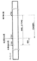
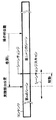
図1を参照して本発明の概略を説明すると、例えば、再生モードを正方向サーチ再生モードから通常再生モードに移行させるためのユーザによる操作を検出したならば、その時のコンテンツのタイムスタンプTSAから補正時間(後述する。)ΔTSABに相当する距離だけ戻ったタイムスタンプTSBの位置(見積頭出位置)まで、コンテンツを巻き戻し、見積頭出位置から通常再生を開始する。そして、真にユーザが通常再生を開始したいと希望していた位置(希望頭出位置)のタイムスタンプTSCから見積頭出位置のタイムスタンプTSBを差し引いた時間を誤差時間ΔTSBCとして算出し、補正時間ΔTSABから誤差時間TSBCを差し引いた時間を新たな補正時間ΔTSAB’とする。 The outline of the present invention will be described with reference to FIG. 1. For example, if an operation by the user for shifting the playback mode from the forward search playback mode to the normal playback mode is detected, the time stamp TSA of the content at that time is detected. The content is rewound to the position of the time stamp TSB (estimated cue position) returned by a correction time (described later) ΔTSAB, and normal playback is started from the estimated cue position. Then, a time obtained by subtracting the time stamp TSB of the estimated head position from the time stamp TSC of the position (desired head position) where the user really wanted to start normal reproduction is calculated as an error time ΔTSBC, and the correction time A time obtained by subtracting the error time TSBC from ΔTSAB is set as a new correction time ΔTSAB ′.
こうすることにより、次回に同様な動作をした時に、タイムスタンプTSBとタイムスタンプTSCが一致することとなり、ユーザは、タイムスタンプTSBの位置からタイムスタンプTSCの位置までコンテンツを巻き戻したり、進めたりする必要が無くなる。 By doing this, when the same operation is performed next time, the time stamp TSB and the time stamp TSC coincide with each other, and the user rewinds or advances the content from the position of the time stamp TSB to the position of the time stamp TSC. There is no need to do.
本発明を適用する再生モードの遷移は、サーチ再生モードから通常再生モードへの遷移のみならず、サーチ再生モードからサーチ再生モード以外の再生モードである。サーチ再生モードの速度は、例えば、数倍速〜数十倍速である。サーチ再生モード以外の再生モードには、通常再生モードのみならず、早見再生モード、スロー再生モード、コマ送り再生モード、ジョグ再生モード、静止画再生モード及び逆転再生モードが含まれる。ここで、通常再生モードの再生速度は、1倍速であり、早見再生モードの再生速度は、1を超える数倍速(例えば、1.5倍、2倍、2.5倍、3倍、3.5倍、4倍、…)であり、スロー再生モードの再生速度は、0を超え1未満(例えば、1/2倍、1/3倍、1/4倍、1/5倍、…)であり、静止画再生モードの再生速度は、0であり、逆転再生モードの再生速度は、0未満マイナス数倍速(例えば、−4倍速、−3.5倍速、−3倍速、−2.5倍速、−2倍速、−1.5倍速、−1倍速、−1/2倍速、−3/1倍速、−1/4倍速、−1/5倍速等)である。コマ送り再生モードでは、通常は静止画再生を行い、コマ送りボタンが押された時に1フレーム正転又は逆転する。ジョグ再生モードでは、ジョグダイアルの回転量に応じて、フレームが正方向又は逆方向に進む。 The transition of the playback mode to which the present invention is applied is not only a transition from the search playback mode to the normal playback mode, but also a playback mode other than the search playback mode from the search playback mode. The speed of the search reproduction mode is, for example, several times speed to several tens times speed. Playback modes other than the search playback mode include not only the normal playback mode but also the fast-play playback mode, slow playback mode, frame advance playback mode, jog playback mode, still image playback mode, and reverse playback mode. Here, the playback speed in the normal playback mode is 1 × speed, and the playback speed in the fast-view playback mode is several times faster than 1 (for example, 1.5 ×, 2 ×, 2.5 ×, 3 ×, 3. 5 times, 4 times,..., And the playback speed in the slow playback mode is greater than 0 and less than 1 (for example, 1/2 times, 1/3 times, 1/4 times, 1/5 times,...). Yes, the playback speed of the still image playback mode is 0, and the playback speed of the reverse playback mode is less than 0 minus several times speed (for example, -4 times speed, -3.5 times speed, -3 times speed, -2.5 times speed) -2 times speed, -1.5 times speed, -1 times speed, -1/2 times speed, -3/1 times speed, -1/4 times speed, -1/5 times speed, etc.). In the frame advance playback mode, still image playback is normally performed, and when the frame advance button is pressed, one frame is rotated forward or backward. In the jog playback mode, the frame advances in the forward direction or the reverse direction according to the amount of rotation of the jog dial.
また、サーチ再生ボタンを押している最中にサーチ再生が行われ、サーチ再生ボタンから指が離されると通常再生モードに移行するのであれば、サーチモード再生から通常再生モードに移行させるためのユーザによる操作を検出する時とは、サーチ再生ボタンから指が離されたことを検出した時である。また、サーチ再生ボタンを一度押せば、その後サーチ再生ボタンを押さなくても、サーチ再生を行い、サーチ再生の最中に通常再生ボタンが押された時に、サーチ再生モードから通常再生モードへ移行するのであれば、サーチモード再生から通常再生モードに移行させるためのユーザによる操作を検出する時とは、通常再生ボタンが押されたことを検出スタ時である。但し、速度サーボ部への速度指示信号の変化時をサーチモード再生から通常再生モードに移行させるためのユーザによる操作を検出する時としてもよい。 If the search playback is performed while the search playback button is being pressed and the normal playback mode is entered when the finger is released from the search playback button, a user for switching from the search mode playback to the normal playback mode is used. The operation is detected when it is detected that the finger is released from the search reproduction button. Also, once the search playback button is pressed, search playback is performed without pressing the search playback button. When the normal playback button is pressed during search playback, the search playback mode is switched to the normal playback mode. In this case, the time when the user's operation for shifting from the search mode playback to the normal playback mode is detected is when the normal playback button is pressed. However, the time when the speed instruction signal to the speed servo unit is changed may be a time when an operation by the user for shifting from the search mode reproduction to the normal reproduction mode is detected.
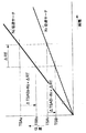
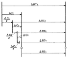
次に、図2を参照して、本発明の原理を説明する。判断時間及び反射時間を含む遅延時間の見積値(見積遅延時間)は、ΔRTであり、サーチ再生の速度に依存しないと仮定する。N1倍速のサーチ再生の場合には、見積遅延時間ΔRTにサーチ再生速度N1を乗じることにより補正時間ΔTSAB1を求める(ΔTSAB1=N1×ΔRT)。次に、タイムスタンプTSA1の位置から補正時間ΔTSAB1に相当する距離だけコンテンツ巻き戻し、こうすることにより、コンテンツをタイムスタンプTSB1の位置まで至らせる(TSB1=TSA1−ΔTSAB1)。N2倍速のサーチ再生の場合には、見積遅延時間ΔRTにサーチ再生速度N2を乗じることにより補正時間ΔTSAB2を求める(ΔTSAB2=N2×ΔRT)。次に、タイムスタンプTSA2の位置から補正時間ΔTSAB2に相当する距離だけコンテンツ巻き戻し、こうすることにより、コンテンツをタイムスタンプTSB2の位置まで至らせる(TSB2=TSA2−ΔTSAB2)。従って、サーチ再生の速度が変化しても、遅延時間に対応した距離だけコンテンツを巻き戻すことが可能となる。なお、逆転サーチ再生をしている場合は、巻き戻しが早送りに変わる点を除き、正転サーチ再生の場合と同様である。 Next, the principle of the present invention will be described with reference to FIG. It is assumed that the estimated value of the delay time (estimated delay time) including the judgment time and the reflection time is ΔRT and does not depend on the search reproduction speed. In the case of N 1 × speed search reproduction, the correction time ΔTSAB 1 is obtained by multiplying the estimated delay time ΔRT by the search reproduction speed N 1 (ΔTSAB 1 = N 1 × ΔRT). Next, the content is rewound from the position of the time stamp TSA 1 by a distance corresponding to the correction time ΔTSAB 1, and thereby the content is brought to the position of the time stamp TSB 1 (TSB 1 = TSA 1 −ΔTSAB 1 ). In the case of N 2 times speed search reproduction, the correction time ΔTSAB 2 is obtained by multiplying the estimated delay time ΔRT by the search reproduction speed N 2 (ΔTSAB 2 = N 2 × ΔRT). Next, the content is rewound by the distance corresponding to the correction time ΔTSAB 2 from the position of the time stamp TSA 2 , and thereby the content is brought to the position of the time stamp TSB 2 (TSB 2 = TSA 2 −ΔTSAB 2 ). Therefore, even if the search reproduction speed changes, the content can be rewound by a distance corresponding to the delay time. The reverse search reproduction is the same as the normal search reproduction except that the rewind is changed to fast forward.
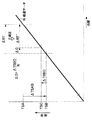
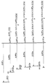
次に、図3を参照して、見積遅延時間の補正方法について説明する。図2では、2種類のサーチ速度N1及びN2の場合を示したが、図3では、両者を代表して、サーチ速度がNであるとする。タイムスタンプTSAの位置から補正時間ΔTSABだけ巻き戻されたタイムスタンプTSBの位置は、見積遅延時間ΔRTに基づいた位置であり、見積遅延時間ΔRTに誤差が含まれている場合には、真にユーザが頭出をしたい位置(タイムスタンプTSC)の位置と一致しない。 Next, a method for correcting the estimated delay time will be described with reference to FIG. FIG. 2 shows the case of two types of search speeds N 1 and N 2. In FIG. 3, it is assumed that the search speed is N on behalf of both. The position of the time stamp TSB that has been rewound by the correction time ΔTSAB from the position of the time stamp TSA is a position based on the estimated delay time ΔRT, and if the estimated delay time ΔRT includes an error, the user is truly Does not match the position (time stamp TSC) at which cueing is desired.
そこで、タイムスタンプTSCからタイムスタンプTSBを差し引くことによりタイムスタンプ換算誤差ΔTSBCを得て(ΔTSBC=TSC−TSB)、これをサーチ速度Nで除することにより見積遅延時間誤差ΔCを得て(ΔC=ΔTSBC/N)、見積遅延時間ΔRTから見積遅延時間誤差ΔCを差し引くことにより、見積遅延時間ΔRTを更新する(ΔRT’=ΔRT−ΔC=ΔRT−ΔTSBC/N)。 Therefore, a time stamp conversion error ΔTSBC is obtained by subtracting the time stamp TSB from the time stamp TSC (ΔTSBC = TSC−TSB), and this is divided by the search speed N to obtain an estimated delay time error ΔC (ΔC = ΔTSBC / N), the estimated delay time ΔRT is updated by subtracting the estimated delay time error ΔC from the estimated delay time ΔRT (ΔRT ′ = ΔRT−ΔC = ΔRT−ΔTSBC / N).
こうすることにより、サーチ速度に依存しない見積遅延時間ΔRTが補正されるので、次回以降、サーチ速度が変化しても、タイムスタンプTSBはタイムスタンプTSCと一致することとなる。 By doing so, the estimated delay time ΔRT that does not depend on the search speed is corrected, so that the time stamp TSB matches the time stamp TSC even if the search speed changes from the next time.
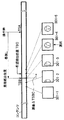
次に、図4を参照して、希望頭出位置のタイムスタンプTSCを得る1つの方法について説明する。コンテンツを見積頭出位置(タイムスタンプがTSBである位置)まで巻き戻したならば、その位置を中心として、所定の範囲のサムネイル画像301−1乃至301−5を一覧表示する。そして、ユーザに頭出し位置の画像を選択させ、ユーザにより選択された画像がある位置のタイムスタンプを希望頭出位置のタイムスタンプTSCとする。 Next, with reference to FIG. 4, one method for obtaining the time stamp TSC at the desired cueing position will be described. When the content is rewound to the estimated head position (the position where the time stamp is TSB), thumbnail images 301-1 to 301-5 in a predetermined range are displayed as a list centering on the position. Then, the user selects an image at the cue position, and the time stamp at the position where the image selected by the user is located is set as the time stamp TSC at the desired cue position.
サムネイル画像301−1乃至301−5は、一定間隔の複数位置の画像であってもよいし、見積頭出位置からの距離が短い順に上位の位置にあるシーンチェンジ直後の画像であってもよい。シーンチェンジ検出をするためには、例えば、特許文献3又は4に記載されている発明を利用することができる。
The thumbnail images 301-1 to 301-5 may be images at a plurality of positions at regular intervals, or may be images immediately after a scene change at a higher position in order of shorter distance from the estimated cue position. . In order to detect a scene change, for example, the invention described in
また、図5に示すように、ユーザからの選択を待たずに、見積頭出位置からの距離が最も短い位置にあるシーンチェンジのタイムスタンプをタイムスタンプTSCとして、自動的に通常再生を開始し、更に、自動的に見積遅延時間ΔRTを補正しても良い。 In addition, as shown in FIG. 5, normal playback is automatically started without waiting for selection from the user, using the time stamp of the scene change at the position where the distance from the estimated cue position is the shortest as the time stamp TSC. Furthermore, the estimated delay time ΔRT may be automatically corrected.
次に、見積遅延時間ΔRTの補正方法のバリエーションについて説明する。 Next, variations of the method for correcting the estimated delay time ΔRT will be described.
上述の例では、見積遅延時間ΔRTから見積遅延時間誤差ΔCを差し引くことにより、見積遅延時間を補正した(ΔRT’=ΔRT−ΔC)。しかし、このような補正を行うと、単に、前回補正された見積遅延時間を次回に適用するのみであり、前回の補正が誤りであれば、次回の見積遅延時間は誤ったものとなってしまう。 In the above example, the estimated delay time is corrected by subtracting the estimated delay time error ΔC from the estimated delay time ΔRT (ΔRT ′ = ΔRT−ΔC). However, when such correction is performed, the estimated delay time corrected last time is simply applied to the next time, and if the previous correction is incorrect, the next estimated delay time is incorrect. .
そこで、例えば、図6に示すように、見積遅延時間ΔRTから見積遅延時間誤差ΔCに1未満の係数(図6の例では1/2)を掛けた値を見積遅延時間ΔRTから差し引くことにより、見積遅延時間を補正する(ΔRT’=ΔRT−a×ΔC)。こうすることにより、すでに見積遅延時間ΔRTが正しい値に収束し、連続して見積遅延時間誤差ΔCがほぼゼロとなった後に、錯誤的に1回だけ見積遅延時間誤差ΔCの大きな値になったとしても、見積遅延時間ΔRTが大きく補正されることが無くなる。 Therefore, for example, as shown in FIG. 6, by subtracting a value obtained by multiplying the estimated delay time error RT from the estimated delay time error ΔC by a coefficient less than 1 (1/2 in the example of FIG. 6) from the estimated delay time ΔRT, The estimated delay time is corrected (ΔRT ′ = ΔRT−a × ΔC). By doing this, the estimated delay time ΔRT has already converged to the correct value, and after the estimated delay time error ΔC has become substantially zero continuously, the estimated delay time error ΔC has become a large value only once by mistake. However, the estimated delay time ΔRT is not greatly corrected.
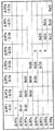
また、図7に示すように、過去の複数回にわたるΔRT−ΔCを基に、見積遅延時間ΔRTを補正しても良い。図7の例では、ΔRT2を求める場合には、過去の1回のΔRT−ΔCを基に、見積遅延時間を補正する。使用を開始してから間もない頃に、過去の複数回にわたるΔRT−ΔCが蓄積されていない場合には、1回の過去のΔRT−ΔCのみを利用することにより、最速に見積遅延時間を正しい値まで持っていくことができる。ΔRT3を求める場合には、過去の2回のΔRT−ΔCを基に見積遅延時間を補正する。使用を開始してから間もない頃に、過去の所定の複数回にわたるΔRT−ΔCが蓄積されていない場合には、所定の複数回未満の数の過去のΔRT−ΔCのみを利用することにより、早く且つある程度の信頼性を伴って見積遅延時間を正しい値まで持っていくことができる。ΔRT3、ΔRT4、ΔRT5、…を求める場合には、過去の3回のΔRT−ΔCを基に見積遅延時間を補正する。使用を開始してから使用回数が一定回数以上になり、過去の所定の複数回にわたるΔRT−ΔCが蓄積されている場合には、所定の複数回の過去のΔRT−ΔCのみを利用することにより、かなりの信頼性を伴って見積遅延時間を微調整することができる。図7の例では、過去の3回のΔRT−ΔCを基に見積遅延時間を補正する状態が定常状態であるとしたが、過去の4回以上のΔRT−ΔCを基に見積遅延時間を補正する状態が定常状態であるとしてもよい。 Further, as shown in FIG. 7, the estimated delay time ΔRT may be corrected based on ΔRT−ΔC over a plurality of past times. In the example of FIG. 7, when ΔRT 2 is obtained, the estimated delay time is corrected based on the past ΔRT−ΔC. When ΔRT−ΔC has not been accumulated several times before the start of use, the estimated delay time is set to the fastest by using only one past ΔRT−ΔC. You can bring it to the correct value. When ΔRT 3 is obtained, the estimated delay time is corrected based on the past two ΔRT−ΔC. When ΔRT-ΔC for a plurality of past predetermined times has not been accumulated shortly after the start of use, by using only a number of past ΔRT-ΔC less than a predetermined number of times The estimated delay time can be brought to a correct value quickly and with a certain degree of reliability. When obtaining ΔRT 3 , ΔRT 4 , ΔRT 5 ,..., The estimated delay time is corrected based on the past three ΔRT−ΔC. When the number of uses exceeds a certain number after the start of use and ΔRT-ΔC over a plurality of past predetermined times is accumulated, only the past ΔRT-ΔC of a predetermined number of times is used. The estimated delay time can be fine tuned with considerable reliability. In the example of FIG. 7, the state in which the estimated delay time is corrected based on the past three ΔRT−ΔC is a steady state, but the estimated delay time is corrected based on the past four or more ΔRT−ΔC. The state to be performed may be a steady state.
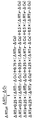
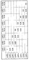
図7の例では、過去の3回のΔRT−ΔCを等しい重みで利用することとしたが、図8に示すように、加重平均を取っても良い。図8の例では、最近のΔRT−ΔCに対して重みを重くしている。 In the example of FIG. 7, the past three ΔRT−ΔC are used with equal weights, but a weighted average may be taken as shown in FIG. 8. In the example of FIG. 8, the weight is increased with respect to the recent ΔRT−ΔC.
図9は、図8の例を表で表したものである。 FIG. 9 is a table showing the example of FIG.
図10は、図8の表を一般化したものである。各行の全ての重みの和は1でなければならない。例えば、
a1(2)+a2(2)=1
a1(3)+a2(3)+a3(3)=1
である。しかし、重みについてのそれ以外の制限はない。
FIG. 10 is a generalization of the table of FIG. The sum of all weights in each row must be 1. For example,
a 1 (2) + a 2 (2) = 1
a 1 (3) + a 2 (3) + a 3 (3) = 1
It is. However, there are no other restrictions on the weight.
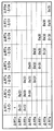
図11の例では、ΔRT6、ΔRT7及びΔRT8の計算において、ΔRT5−ΔC5を用いていない。これは、ΔRT5−ΔC5の値が、ΔRT4−ΔC4、ΔRT3−ΔC3、ΔRT2−ΔC2、…と比較してかけ離れた値である。このような場合には、錯誤的にΔRT5−ΔC5の値が得られたと判断して、ΔRT5−ΔC5を用いないこととしている。あるΔRT−ΔCを用いるか用いないかについては、例えば、その前後のΔRT−ΔCの平均値を中心とした所定時間の範囲に入っているか否かに基づいて判断する。また、所定数のΔRT−ΔCを集め、最大値から所定数個のΔRT−ΔC及び最小値から所定数個のΔRT−ΔCを除外するようにしても良い。例えば、過去10回のΔRT−ΔCを集め、最大値をとるΔRT3−ΔC3、2番目の最大値をとるΔRT5−ΔC5、最小値をとるΔRT2−ΔC2及び2番目の最小値をとるΔRT7−ΔC7を除外して、過去8回のΔRT−ΔCの加重平均により、ΔRTを補正しても良い。 In the example of FIG. 11, ΔRT 5 −ΔC 5 is not used in the calculation of ΔRT 6 , ΔRT 7, and ΔRT 8 . This is a value that is far from the value of ΔRT 5 −ΔC 5 compared to ΔRT 4 −ΔC 4 , ΔRT 3 −ΔC 3 , ΔRT 2 −ΔC 2 ,. In such a case, it is judged by mistake that the value of ΔRT 5 -ΔC 5 has been obtained, and ΔRT 5 -ΔC 5 is not used. Whether or not to use a certain ΔRT−ΔC is determined based on, for example, whether or not a certain ΔRT−ΔC is within a predetermined time range centered on an average value of ΔRT−ΔC before and after that. Alternatively, a predetermined number of ΔRT−ΔC may be collected, and a predetermined number of ΔRT−ΔC may be excluded from the maximum value and a predetermined number of ΔRT−ΔC may be excluded from the minimum value. For example, the past 10 ΔRT−ΔC are collected, ΔRT 3 −ΔC 3 taking the maximum value, ΔRT 5 −ΔC 5 taking the second maximum value, ΔRT 2 −ΔC 2 taking the minimum value, and the second minimum value excludes ΔRT 7 -ΔC 7 taking, the weighted average of the past eight ΔRT-ΔC, may be corrected DerutaRT.
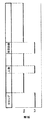
サーチ速度は一定でなくても良いことを上述したが、例えば、図12に示すように、テロップが含まれている画像、人物が含まれている画像及び特定画像が含まれている画像において、サーチ速度を遅くして、その他の画像において、サーチ速度を速くするようにしても良い。勿論、テロップが含まれている画像のみにおいてサーチ速度を遅くしてもよいし、人物が含まれている画像のみにおいてサーチ速度を遅くしてもよいし、特定画像が含まれている画像のみにおいてサーチ速度を遅くしてもよい。 As described above, the search speed may not be constant. For example, as illustrated in FIG. 12, in an image including a telop, an image including a person, and an image including a specific image, The search speed may be decreased to increase the search speed for other images. Of course, the search speed may be slowed only for images containing telops, the search speed may be slowed only for images containing people, or only for images containing specific images. The search speed may be slowed down.
テロップが含まれている画像を検出するためには、例えば、特許文献5に記載されている発明を利用することができる。人物が含まれている画像を検出するためには、例えば、特許文献6、特許文献7及び非特許文献1に記載されている発明を利用することができる。特定画像が含まれている画像を検出するためには、例えば、特許文献5及び非特許文献2に記載されている発明を利用することができる。
In order to detect an image including a telop, for example, the invention described in Patent Document 5 can be used. In order to detect an image including a person, for example, the inventions described in Patent Document 6, Patent Document 7, and
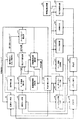
次に、本実施形態の具体的な構成及び動作について、図13、14及び15を参照して説明する。 Next, a specific configuration and operation of the present embodiment will be described with reference to FIGS.
図13を参照すると、本実施形態によるコンテンツ頭出位置制御装置は、ドライブ103、位置サーボ部105、速度サーボ部107、サーチ速度検出部109、操作検出部111、見積遅延時間格納部113、補正時間算出部115、操作時タイムスタンプ取得部117、タイムスタンプ補正部119、見積遅延時間補正部121、希望位置入力部123、ユーザインターフェース部125、再生部127、シーンチェンジ検出部129、テロップ検出部131、人物検出部133、特定画像検出部135、サーチ速度指示部137及び特定画像指定部139を備える。なお、これらの部分はハードウェアによって実現することもできるが、コンピュータをこれらの部分として機能させるためのプログラムをコンピュータが読み込んで実行することによっても実現することができる。
Referring to FIG. 13, the content cue position control apparatus according to the present embodiment includes a
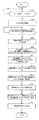
まず、全体の動作について、図13及び14を参照して説明する。 First, the overall operation will be described with reference to FIGS.
まず、操作検出部111は、ユーザインターフェース部125を介して、サーチ再生モードに移行したか否かを判断する(ステップS201)。又は、サーチ速度検出部109が、速度サーボ部107から得られる目標速度又は実際の速度を検出することにより、サーチ再生モードに移行したか否かを判断しても良い。次に、サーチ速度検出部109は、速度サーボ部107から得られる目標速度又は実際の速度をサーチ速度Nとして検出する(ステップS203)。次に、操作検出部111は、ユーザインターフェース部125を介して、サーチ再生モード以外の再生モードに移行したか否かを判断する(ステップS205)。
First, the
次に、操作時タイムスタンプ取得部117は、位置サーボ部105から得られるタイムスタンプ及び操作検出部111から得られるモード以降検出信号に基づいて、サーチ再生モードから他の再生モードに移行するための操作が行われた瞬間のタイムスタンプTSAを検出する(ステップS207)。
Next, the operation time stamp acquisition unit 117 is for shifting from the search reproduction mode to another reproduction mode based on the time stamp obtained from the
次に、補正時間算出部115は、見積遅延時間格納部113から得られる見積遅延時間ΔRTにサーチ速度検出部109から得られるサーチ速度Nを乗ずることにより、補正時間ΔTSABを得る(ステップS209)。
Next, the correction time calculation unit 115 obtains the correction time ΔTSAB by multiplying the estimated delay time ΔRT obtained from the estimated delay
次に、タイムスタンプ補正部119は、操作時タイムスタンプ取得部117から得られる操作検出時のタイムスタンプTSAから補正時間ΔTSABを差し引くことにより、見積始動タイムスタンプTSBを得る(ステップS211)。
Next, the time
次に、位置サーボ部105は、ドライブ103を駆動することにより、見積始動タイムスタンプTSBの位置までコンテンツ媒体101に記録されているコンテンツを移動させる(ステップS213)。
Next, the
次に、位置サーボ部105による制御により、見積始動タイムスタンプTSBの位置を中心とする所定範囲の所定数の画像を再生部127により再生し、ユーザインターフェース部125は、それらのサムネイル画像を画面に一覧表示する(ステップS215)。又は、位置サーボ部105による制御により、見積始動タイムスタンプTSBの位置を中心とする所定範囲の画像を再生部127により再生し、シーンチェンジ検出部129が、再生画像からシーンチェンジを検出し、ユーザインターフェース部125は、1以上のシーンチェンジ直後のサムネイル画像を画面に一覧表示するようにしてもよい。
Next, under the control of the
次に、ユーザインターフェース部125は、ユーザにより選択されたサムネイル画像を識別する(ステップS217)。次に、希望位置入力部123は、ステップS217で識別されたサムネイル画像に対応するタイムスタンプを希望位置タイムスタンプTSCとして検出する(ステップS219)。次に、見積遅延時間補正部121は、見積始動タイムスタンプTSB、希望位置タイムスタンプTSC及びサーチ速度Nに基づいて、見積遅延時間ΔRTを補正し、補正後の見積遅延時間ΔRTを見積遅延時間格納部113に格納する(ステップ221)。
Next, the
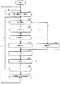
次に、サーチ速度の制御について、図13及び15を参照して説明する。 Next, search speed control will be described with reference to FIGS.
まず、ユーザインターフェース部125は、ユーザからの再生モード指示の信号を基に、サーチ再生モードに移行したか否かを判断する(ステップS251)。
First, the
サーチ再生モードに移行したならば(ステップS251でYES)、テロップ検出部131は、再生されている画像にテロップが含まれているか否かを検出する(ステップS253)。再生されている画像にテロップが含まれている場合にはステップS261に進み、そうでない場合にはステップS255に進む。
If the search reproduction mode is entered (YES in step S251), the
ステップS255では、人物検出部133は、再生されている画像に人物が含まれているか否かを検出する。再生されている画像に人物が含まれている場合にはステップS261に進み、そうでない場合にはステップS257に進む。
In step S255, the
ステップS257では、特定画像検出部135は、再生されている画像に特定画像指定部139にて指定された特定画像が含まれているか否かを検出する。再生されている画像に特定画像が含まれている場合にはステップS261に進み、そうでない場合にはステップS259に進む。
In step S257, the specific
ステップS259では、サーチ再生の速度をN2に設定する。ステップS261では、サーチ再生の速度をN1に設定する(N1<N2)。 In step S259, the search reproduction speed is set to N2. In step S261, the search reproduction speed is set to N1 (N1 <N2).
次に、サーチ再生モード以外の再生モードに移行するためのユーザからの入力があれば(ステップS269でYES)、ステップS251に戻り、一定時間が経過すれば(ステップS267でYES)、ステップS253に戻る。ここで、時間の計測のために一次変数Iを用いている(ステップS263及びS265)。 Next, if there is an input from the user to shift to a playback mode other than the search playback mode (YES in step S269), the process returns to step S251, and if a certain time has passed (YES in step S267), the process returns to step S253. Return. Here, the primary variable I is used for time measurement (steps S263 and S265).
なお、サーチ速度指示部137が、ステップS253、S255及びS257の判断を行い、ステップS259及びS261の速度設定を行い、設定された速度を速度サーボ部107に目標速度として与える。
Note that the search
本発明は、ハードディスクドライブ、DVD又はビデオテープレコーダ等に記録されたコンテンツをサーチ再生した後に通常再生、スロー再生、静止画再生等のサーチ再生とは異なる第2の再生モードで再生する場合に、第2の再生モードにおける再生の頭出位置を制御するために利用することができる。 The present invention is a case where the content recorded in a hard disk drive, DVD or video tape recorder or the like is played back in a second playback mode different from search playback such as normal playback, slow playback and still image playback after search playback. This can be used to control the cue position of reproduction in the second reproduction mode.
101 コンテンツ媒体
103 ドライブ
105 位置サーボ部
107 速度サーボ部
109 サーチ速度検出部
111 操作検出部
113 見積遅延時間格納部
115 補正時間算出部
117 操作時タイムスタンプ取得部
119 タイムスタンプ補正部
121 見積遅延時間補正部
123 希望位置入力部
125 ユーザインターフェース部
127 再生部
129 シーンチェンジ検出部
131 テロップ検出部
133 人物検出部
135 特定画像検出部
137 サーチ速度指示部
139 特定画像指定部
DESCRIPTION OF
Claims (22)
見積遅延時間に前記サーチ再生の速度を乗じることにより、補正時間を得る補正時間算出ステップと、
前記操作が行われた瞬間の前記コンテンツのタイムスタンプから前記補正時間を差し引くことにより、見積始動タイムスタンプを得るタイムスタンプ補正ステップと、
前記ユーザが希望する希望位置のタイムスタンプを入力する希望位置入力ステップと、
前記見積始動タイムスタンプ、前記希望位置タイムスタンプ及び前記サーチ再生の速度に基づいて、前記見積遅延時間を補正する見積遅延時間補正ステップと、
を備えることを特徴とするコンテンツ頭出位置制御方法。 An operation detecting step for detecting that an operation for shifting the content reproduction mode from the search reproduction mode to another reproduction mode is performed by the user;
A correction time calculation step of obtaining a correction time by multiplying the estimated delay time by the search reproduction speed;
A time stamp correction step of obtaining an estimated start time stamp by subtracting the correction time from a time stamp of the content at the moment when the operation is performed;
A desired position input step for inputting a time stamp of a desired position desired by the user;
An estimated delay time correcting step of correcting the estimated delay time based on the estimated start time stamp, the desired position time stamp and the search reproduction speed;
A content cue position control method comprising:
前記見積遅延時間補正ステップは、
前記見積始動タイムスタンプと前記希望位置タイムスタンプとの差分を前記サーチ再生の速度で除して得た時間に所定の係数を乗じて得た時間を前記見積遅延時間から減ずることにより、前記見積遅延時間を補正することを特徴とするコンテンツ頭出位置制御方法。 The content cue position control method according to claim 1,
The estimated delay time correction step includes:
The estimated delay time is obtained by subtracting, from the estimated delay time, a time obtained by multiplying a time obtained by dividing the difference between the estimated start time stamp and the desired position time stamp by the search reproduction speed by a predetermined coefficient. A content cue position control method characterized by correcting time.
前記見積遅延時間補正ステップは、複数回の頭出しに亘る前記見積始動タイムスタンプ、前記希望位置タイムスタンプ及び前記サーチ再生の速度に基づいて、前記見積遅延時間を補正することを特徴とするコンテンツ頭出位置制御方法。 The content cue position control method according to claim 1,
The estimated delay time correcting step corrects the estimated delay time based on the estimated start time stamp, the desired position time stamp, and the search reproduction speed over a plurality of times. Exit position control method.
前記見積遅延時間補正ステップは、
前記見積始動タイムスタンプから前記希望位置タイムスタンプとの差分を前記サーチ再生の速度で除して得た時間を前記見積遅延時間から減ずることにより得た時間の複数回の頭出しに亘る加重平均を、新たな見積遅延時間とすることを特徴とするコンテンツ頭出位置制御方法。 In the content cue position control method according to claim 3,
The estimated delay time correction step includes:
A weighted average over a plurality of cue times obtained by subtracting the time obtained by dividing the difference between the estimated start time stamp and the desired position time stamp by the search reproduction speed from the estimated delay time. A content cueing position control method characterized by setting a new estimated delay time.
前記サーチ再生の速度をコンテンツの内容によって変化させるサーチ速度制御ステップを更に備えることを特徴とするコンテンツ頭出位置制御方法。 The content cue position control method according to claim 1,
A content cue position control method, further comprising a search speed control step of changing the search reproduction speed according to contents.
前記サーチ速度制御ステップは、テロップ画像、人物が含まれる画像及び特定画像のうちの少なくとも1つの部分でサーチ速度を第1の速度とし、他の部分でサーチ速度を前記第1の速度よりも早い第2の速度とすることを特徴とするコンテンツ頭出位置制御方法。 The content cue position control method according to claim 5,
In the search speed control step, the search speed is set to a first speed in at least one part of the telop image, the image including the person, and the specific image, and the search speed is set to be higher than the first speed in the other part. A content cueing position control method, characterized in that the second speed is set.
前記見積始動タイムスタンプ位置を含む所定範囲の複数の位置のコンテンツを一覧表示する表示ステップを更に備えることを特徴とするコンテンツ頭出位置制御方法。 The content cue position control method according to claim 1,
A content cue position control method further comprising a display step of displaying a list of contents at a plurality of positions within a predetermined range including the estimated start time stamp position.
前記見積始動タイムスタンプ位置から最も近い順に1以上のシーンチェンジの位置を検出するシーンチェンジ検出ステップと、
前記1以上のシーンチェンジの位置のコンテンツを希望位置の候補のコンテンツとして表示する表示ステップと、
を更に備えることを特徴とするコンテンツ頭出位置制御方法。 The content cue position control method according to claim 1,
A scene change detection step of detecting the position of one or more scene changes in the order closest to the estimated start time stamp position;
A display step of displaying the content at the position of the one or more scene changes as a candidate content of a desired position;
The content cue position control method further comprising:
前記見積始動タイムスタンプ位置から最も近いシーンチェンジの位置を検出するシーンチェンジ検出ステップを更に備え、
前記希望位置入力ステップは、前記シーンチェンジ位置を前記希望位置とみなすことを特徴とするコンテンツ頭出位置制御方法。 The content cue position control method according to claim 1,
A scene change detecting step of detecting a scene change position closest to the estimated start time stamp position;
The desired position input step, wherein the scene change position is regarded as the desired position.
前記他の再生モードは、通常再生、早見再生、スロー再生、コマ送り再生、ジョグ再生、静止画再生及び逆転再生のうちの何れかであることを特徴とするコンテンツ頭出位置制御方法。 The content cue position control method according to claim 1,
2. The content cue position control method according to claim 1, wherein the other playback mode is any one of normal playback, quick-view playback, slow playback, frame advance playback, jog playback, still image playback, and reverse playback.
見積遅延時間に前記サーチ再生の速度を乗じることにより、補正時間を得る補正時間算出手段と、
前記操作が行われた瞬間の前記コンテンツのタイムスタンプから前記補正時間を差し引くことにより、見積始動タイムスタンプを得るタイムスタンプ補正手段と、
前記ユーザが希望する希望位置のタイムスタンプを入力する希望位置入力手段と、
前記見積始動タイムスタンプ、前記希望位置タイムスタンプ及び前記サーチ再生の速度に基づいて、前記見積遅延時間を補正する見積遅延時間補正手段と、
を備えることを特徴とするコンテンツ頭出位置制御装置。 Operation detecting means for detecting that an operation for shifting the content reproduction mode from the search reproduction mode to another reproduction mode is performed by the user;
A correction time calculation means for obtaining a correction time by multiplying the estimated delay time by the search reproduction speed;
Time stamp correction means for obtaining an estimated start time stamp by subtracting the correction time from the time stamp of the content at the moment when the operation is performed;
A desired position input means for inputting a time stamp of a desired position desired by the user;
Estimated delay time correcting means for correcting the estimated delay time based on the estimated start time stamp, the desired position time stamp, and the search reproduction speed;
A content cueing position control device comprising:
前記見積遅延時間補正手段は、
前記見積始動タイムスタンプと前記希望位置タイムスタンプとの差分を前記サーチ再生の速度で除して得た時間に所定の係数を乗じて得た時間を前記見積遅延時間から減ずることにより、前記見積遅延時間を補正することを特徴とするコンテンツ頭出位置制御装置。 The content cue position control device according to claim 11,
The estimated delay time correcting means includes
The estimated delay time is obtained by subtracting, from the estimated delay time, a time obtained by multiplying a time obtained by dividing the difference between the estimated start time stamp and the desired position time stamp by the search reproduction speed by a predetermined coefficient. A content cue position control apparatus characterized by correcting time.
前記見積遅延時間補正手段は、複数回の頭出しに亘る前記見積始動タイムスタンプ、前記希望位置タイムスタンプ及び前記サーチ再生の速度に基づいて、前記見積遅延時間を補正することを特徴とするコンテンツ頭出位置制御装置。 The content cue position control device according to claim 11,
The estimated delay time correcting means corrects the estimated delay time based on the estimated start time stamp, the desired position time stamp, and the search reproduction speed over a plurality of times. Exit position control device.
前記見積遅延時間補正手段は、
前記見積始動タイムスタンプから前記希望位置タイムスタンプとの差分を前記サーチ再生の速度で除して得た時間を前記見積遅延時間から減ずることにより得た時間の複数回の頭出しに亘る加重平均を、新たな見積遅延時間とすることを特徴とするコンテンツ頭出位置制御装置。 The content cue position control device according to claim 13,
The estimated delay time correcting means includes
A weighted average over a plurality of cue times obtained by subtracting the time obtained by dividing the difference between the estimated start time stamp and the desired position time stamp by the search reproduction speed from the estimated delay time. A content cue position control apparatus characterized by setting a new estimated delay time.
前記サーチ再生の速度をコンテンツの内容によって変化させるサーチ速度制御手段を更に備えることを特徴とするコンテンツ頭出位置制御装置。 The content cue position control device according to claim 11,
A content cue position control apparatus, further comprising search speed control means for changing the search reproduction speed according to the content.
前記サーチ速度制御手段は、テロップ画像、人物が含まれる画像及び特定画像のうちの少なくとも1つの部分でサーチ速度を第1の速度とし、他の部分でサーチ速度を前記第1の速度よりも早い第2の速度とすることを特徴とするコンテンツ頭出位置制御装置。 The content cue position control device according to claim 15,
The search speed control means sets the search speed to the first speed in at least one portion of the telop image, the image including the person, and the specific image, and sets the search speed higher than the first speed in the other portion. A content cueing position control device characterized by a second speed.
前記見積始動タイムスタンプ位置を含む所定範囲の複数の位置のコンテンツを一覧表示する表示手段を更に備えることを特徴とするコンテンツ頭出位置制御装置。 The content cue position control device according to claim 11,
The content cue position control apparatus further comprising display means for displaying a list of contents at a plurality of positions within a predetermined range including the estimated start time stamp position.
前記見積始動タイムスタンプ位置から最も近い順に1以上のシーンチェンジの位置を検出するシーンチェンジ検出手段と、
前記1以上のシーンチェンジの位置のコンテンツを希望位置の候補のコンテンツとして表示する表示手段と、
を更に備えることを特徴とするコンテンツ頭出位置制御装置。 The content cue position control device according to claim 11,
Scene change detection means for detecting the position of one or more scene changes in the order closest to the estimated start time stamp position;
Display means for displaying the content at the position of the one or more scene changes as candidate content of the desired position;
The content cueing position control device further comprising:
前記見積始動タイムスタンプ位置から最も近いシーンチェンジの位置を検出するシーンチェンジ検出手段を更に備え、
前記希望位置入力手段は、前記シーンチェンジ位置を前記希望位置とみなすことを特徴とするコンテンツ頭出位置制御装置。 The content cue position control device according to claim 11,
A scene change detecting means for detecting a position of the scene change closest to the estimated start time stamp position;
The content search position control device, wherein the desired position input means regards the scene change position as the desired position.
前記他の再生モードは、通常再生、早見再生、スロー再生、コマ送り再生、ジョグ再生、静止画再生及び逆転再生のうちの何れかであることを特徴とするコンテンツ頭出位置制御装置。 The content cue position control device according to claim 11,
The content search position control apparatus according to claim 1, wherein the other playback mode is any one of normal playback, quick-view playback, slow playback, frame advance playback, jog playback, still image playback, and reverse playback.
Priority Applications (1)
| Application Number | Priority Date | Filing Date | Title |
|---|---|---|---|
| JP2004104567A JP3890335B2 (en) | 2004-03-31 | 2004-03-31 | Content cue position control method, content cue position control device, and content cue position control program |
Applications Claiming Priority (1)
| Application Number | Priority Date | Filing Date | Title |
|---|---|---|---|
| JP2004104567A JP3890335B2 (en) | 2004-03-31 | 2004-03-31 | Content cue position control method, content cue position control device, and content cue position control program |
Publications (2)
| Publication Number | Publication Date |
|---|---|
| JP2005293680A true JP2005293680A (en) | 2005-10-20 |
| JP3890335B2 JP3890335B2 (en) | 2007-03-07 |
Family
ID=35326457
Family Applications (1)
| Application Number | Title | Priority Date | Filing Date |
|---|---|---|---|
| JP2004104567A Expired - Fee Related JP3890335B2 (en) | 2004-03-31 | 2004-03-31 | Content cue position control method, content cue position control device, and content cue position control program |
Country Status (1)
| Country | Link |
|---|---|
| JP (1) | JP3890335B2 (en) |
Cited By (11)
| Publication number | Priority date | Publication date | Assignee | Title |
|---|---|---|---|---|
| WO2007105267A1 (en) * | 2006-03-10 | 2007-09-20 | Fujitsu Limited | Playback device, control method for playback device, program, and computer-readable recording medium |
| JP2008159250A (en) * | 2006-12-21 | 2008-07-10 | Humax Co Ltd | Playback control device and playback control method |
| JP2008312025A (en) * | 2007-06-15 | 2008-12-25 | Victor Co Of Japan Ltd | Video image content data reproduction apparatus |
| JP2009010620A (en) * | 2007-06-27 | 2009-01-15 | Sharp Corp | Playback device |
| JP2010147509A (en) * | 2008-12-16 | 2010-07-01 | Hitachi Ltd | Video processor and video distribution system |
| JP2010226251A (en) * | 2009-03-19 | 2010-10-07 | Canon Inc | Video data display apparatus and method |
| JP2010539746A (en) * | 2007-09-10 | 2010-12-16 | トムソン ライセンシング | Video playback device |
| JP2011130129A (en) * | 2009-12-16 | 2011-06-30 | Canon Inc | Video reproducing device, and control method thereof |
| WO2011138628A1 (en) * | 2010-05-07 | 2011-11-10 | Thomson Licensing | Method and device for optimal playback positioning in digital content |
| US8463112B2 (en) | 2009-01-06 | 2013-06-11 | Canon Kabushiki Kaisha | Playback method and playback apparatus |
| JP2015097426A (en) * | 2015-01-26 | 2015-05-21 | トムソン ライセンシングThomson Licensing | Method and device for optimal playback positioning in digital content |
Families Citing this family (1)
| Publication number | Priority date | Publication date | Assignee | Title |
|---|---|---|---|---|
| US20170093560A1 (en) * | 2015-09-29 | 2017-03-30 | Tektronix, Inc. | Adaptive compensation for internal asymmetric delay in network based timing systems |
-
2004
- 2004-03-31 JP JP2004104567A patent/JP3890335B2/en not_active Expired - Fee Related
Cited By (19)
| Publication number | Priority date | Publication date | Assignee | Title |
|---|---|---|---|---|
| WO2007105267A1 (en) * | 2006-03-10 | 2007-09-20 | Fujitsu Limited | Playback device, control method for playback device, program, and computer-readable recording medium |
| JP2008159250A (en) * | 2006-12-21 | 2008-07-10 | Humax Co Ltd | Playback control device and playback control method |
| JP2008312025A (en) * | 2007-06-15 | 2008-12-25 | Victor Co Of Japan Ltd | Video image content data reproduction apparatus |
| JP2009010620A (en) * | 2007-06-27 | 2009-01-15 | Sharp Corp | Playback device |
| JP2010539746A (en) * | 2007-09-10 | 2010-12-16 | トムソン ライセンシング | Video playback device |
| US9299388B2 (en) | 2007-09-10 | 2016-03-29 | Gvbb Holdings S.A.R.L. | Video playback |
| JP2010147509A (en) * | 2008-12-16 | 2010-07-01 | Hitachi Ltd | Video processor and video distribution system |
| US8463112B2 (en) | 2009-01-06 | 2013-06-11 | Canon Kabushiki Kaisha | Playback method and playback apparatus |
| US8792778B2 (en) | 2009-03-19 | 2014-07-29 | Canon Kabushiki Kaisha | Video data display apparatus and method thereof |
| JP2010226251A (en) * | 2009-03-19 | 2010-10-07 | Canon Inc | Video data display apparatus and method |
| JP2011130129A (en) * | 2009-12-16 | 2011-06-30 | Canon Inc | Video reproducing device, and control method thereof |
| WO2011138628A1 (en) * | 2010-05-07 | 2011-11-10 | Thomson Licensing | Method and device for optimal playback positioning in digital content |
| JP2013532405A (en) * | 2010-05-07 | 2013-08-15 | トムソン ライセンシング | Method and apparatus for optimal playback positioning in digital content |
| KR20130086521A (en) * | 2010-05-07 | 2013-08-02 | 톰슨 라이센싱 | Method and device for optimal playback positioning in digital content |
| US8891936B2 (en) | 2010-05-07 | 2014-11-18 | Thomson Licensing | Method and device for optimal playback positioning in digital content |
| CN102884786A (en) * | 2010-05-07 | 2013-01-16 | 汤姆森特许公司 | Method and device for optimal playback positioning in digital content |
| CN102884786B (en) * | 2010-05-07 | 2016-08-17 | 汤姆森特许公司 | The method and apparatus of optimal playback location in digital content |
| KR101656520B1 (en) * | 2010-05-07 | 2016-09-22 | 톰슨 라이센싱 | Method and device for optimal playback positioning in digital content |
| JP2015097426A (en) * | 2015-01-26 | 2015-05-21 | トムソン ライセンシングThomson Licensing | Method and device for optimal playback positioning in digital content |
Also Published As
| Publication number | Publication date |
|---|---|
| JP3890335B2 (en) | 2007-03-07 |
Similar Documents
| Publication | Publication Date | Title |
|---|---|---|
| US10331512B2 (en) | Adaptive intervals in navigating content and/or media | |
| US8294018B2 (en) | Playback apparatus, playback method and program | |
| KR100422699B1 (en) | Method and apparatus for intelligent video browsing of video contents | |
| JP3890335B2 (en) | Content cue position control method, content cue position control device, and content cue position control program | |
| US20070223871A1 (en) | Method of Generating a Content Item Having a Specific Emotional Influence on a User | |
| US8213764B2 (en) | Information processing apparatus, method and program | |
| KR19980065239A (en) | Apparatus and method for calculating play time of optical disc | |
| KR100555427B1 (en) | Video playback device and intelligent skip method | |
| WO2010122644A1 (en) | Image display system | |
| CN1574930B (en) | Apparatus and method for reproducing video contents | |
| KR100667846B1 (en) | Time shift user interface method with automatic chaptering function and AJ device using the same | |
| US7711240B2 (en) | Reproducing apparatus and reproducing method | |
| JP4277817B2 (en) | Operation history display device, operation history display method and program | |
| JP4461233B2 (en) | MEDIA DATA SELECTION DEVICE, MEDIA DATA SELECTION METHOD, MEDIA DATA SELECTION PROGRAM, AND RECORDING MEDIUM CONTAINING THE PROGRAM | |
| US8433180B2 (en) | Search tool | |
| JP2004282763A (en) | Video reproducing method and system, and apparatus using the same | |
| US20040179817A1 (en) | Method for searching and playing back video data based on caption-based information | |
| JP5441582B2 (en) | Audio apparatus and introscan method | |
| KR100261804B1 (en) | Method for variabling scan speed of optical disc playing apparatus | |
| EP1938327B1 (en) | A search tool | |
| US8121459B2 (en) | Preview method | |
| JP2005276329A (en) | Device with bookmark function | |
| JP2014071915A (en) | Dvd reproduction device | |
| JP2009267457A (en) | Recording and reproducing device | |
| KR20040023080A (en) | Method for displaying digital dictionary in optical disc device |
Legal Events
| Date | Code | Title | Description |
|---|---|---|---|
| A977 | Report on retrieval |
Free format text: JAPANESE INTERMEDIATE CODE: A971007 Effective date: 20060426 |
|
| A131 | Notification of reasons for refusal |
Free format text: JAPANESE INTERMEDIATE CODE: A131 Effective date: 20060508 |
|
| A521 | Written amendment |
Free format text: JAPANESE INTERMEDIATE CODE: A523 Effective date: 20060707 |
|
| A02 | Decision of refusal |
Free format text: JAPANESE INTERMEDIATE CODE: A02 Effective date: 20060728 |
|
| A521 | Written amendment |
Free format text: JAPANESE INTERMEDIATE CODE: A523 Effective date: 20060828 |
|
| RD01 | Notification of change of attorney |
Free format text: JAPANESE INTERMEDIATE CODE: A7421 Effective date: 20060828 |
|
| A521 | Written amendment |
Free format text: JAPANESE INTERMEDIATE CODE: A523 Effective date: 20060914 |
|
| A911 | Transfer to examiner for re-examination before appeal (zenchi) |
Free format text: JAPANESE INTERMEDIATE CODE: A911 Effective date: 20061019 |
|
| TRDD | Decision of grant or rejection written | ||
| A01 | Written decision to grant a patent or to grant a registration (utility model) |
Free format text: JAPANESE INTERMEDIATE CODE: A01 Effective date: 20061114 |
|
| A61 | First payment of annual fees (during grant procedure) |
Free format text: JAPANESE INTERMEDIATE CODE: A61 Effective date: 20061204 |
|
| R150 | Certificate of patent or registration of utility model |
Free format text: JAPANESE INTERMEDIATE CODE: R150 Ref document number: 3890335 Country of ref document: JP Free format text: JAPANESE INTERMEDIATE CODE: R150 |
|
| FPAY | Renewal fee payment (event date is renewal date of database) |
Free format text: PAYMENT UNTIL: 20091208 Year of fee payment: 3 |
|
| FPAY | Renewal fee payment (event date is renewal date of database) |
Free format text: PAYMENT UNTIL: 20101208 Year of fee payment: 4 |
|
| FPAY | Renewal fee payment (event date is renewal date of database) |
Free format text: PAYMENT UNTIL: 20101208 Year of fee payment: 4 |
|
| FPAY | Renewal fee payment (event date is renewal date of database) |
Free format text: PAYMENT UNTIL: 20111208 Year of fee payment: 5 |
|
| S111 | Request for change of ownership or part of ownership |
Free format text: JAPANESE INTERMEDIATE CODE: R313111 |
|
| FPAY | Renewal fee payment (event date is renewal date of database) |
Free format text: PAYMENT UNTIL: 20111208 Year of fee payment: 5 |
|
| S531 | Written request for registration of change of domicile |
Free format text: JAPANESE INTERMEDIATE CODE: R313531 |
|
| S533 | Written request for registration of change of name |
Free format text: JAPANESE INTERMEDIATE CODE: R313533 |
|
| R371 | Transfer withdrawn |
Free format text: JAPANESE INTERMEDIATE CODE: R371 |
|
| FPAY | Renewal fee payment (event date is renewal date of database) |
Free format text: PAYMENT UNTIL: 20111208 Year of fee payment: 5 |
|
| S111 | Request for change of ownership or part of ownership |
Free format text: JAPANESE INTERMEDIATE CODE: R313111 |
|
| FPAY | Renewal fee payment (event date is renewal date of database) |
Free format text: PAYMENT UNTIL: 20111208 Year of fee payment: 5 |
|
| R350 | Written notification of registration of transfer |
Free format text: JAPANESE INTERMEDIATE CODE: R350 |
|
| FPAY | Renewal fee payment (event date is renewal date of database) |
Free format text: PAYMENT UNTIL: 20121208 Year of fee payment: 6 |
|
| FPAY | Renewal fee payment (event date is renewal date of database) |
Free format text: PAYMENT UNTIL: 20121208 Year of fee payment: 6 |
|
| FPAY | Renewal fee payment (event date is renewal date of database) |
Free format text: PAYMENT UNTIL: 20121208 Year of fee payment: 6 |
|
| FPAY | Renewal fee payment (event date is renewal date of database) |
Free format text: PAYMENT UNTIL: 20121208 Year of fee payment: 6 |
|
| FPAY | Renewal fee payment (event date is renewal date of database) |
Free format text: PAYMENT UNTIL: 20131208 Year of fee payment: 7 |
|
| R250 | Receipt of annual fees |
Free format text: JAPANESE INTERMEDIATE CODE: R250 |
|
| R250 | Receipt of annual fees |
Free format text: JAPANESE INTERMEDIATE CODE: R250 |
|
| R250 | Receipt of annual fees |
Free format text: JAPANESE INTERMEDIATE CODE: R250 |
|
| R250 | Receipt of annual fees |
Free format text: JAPANESE INTERMEDIATE CODE: R250 |
|
| R250 | Receipt of annual fees |
Free format text: JAPANESE INTERMEDIATE CODE: R250 |
|
| R250 | Receipt of annual fees |
Free format text: JAPANESE INTERMEDIATE CODE: R250 |
|
| R250 | Receipt of annual fees |
Free format text: JAPANESE INTERMEDIATE CODE: R250 |
|
| R250 | Receipt of annual fees |
Free format text: JAPANESE INTERMEDIATE CODE: R250 |
|
| LAPS | Cancellation because of no payment of annual fees |