JP2005293662A - Magnetic recording medium, manufacturing method thereof, and imprint stamper - Google Patents
Magnetic recording medium, manufacturing method thereof, and imprint stamper Download PDFInfo
- Publication number
- JP2005293662A JP2005293662A JP2004103850A JP2004103850A JP2005293662A JP 2005293662 A JP2005293662 A JP 2005293662A JP 2004103850 A JP2004103850 A JP 2004103850A JP 2004103850 A JP2004103850 A JP 2004103850A JP 2005293662 A JP2005293662 A JP 2005293662A
- Authority
- JP
- Japan
- Prior art keywords
- servo
- imprint
- magnetic film
- resist
- region
- Prior art date
- Legal status (The legal status is an assumption and is not a legal conclusion. Google has not performed a legal analysis and makes no representation as to the accuracy of the status listed.)
- Granted
Links
Images

Landscapes
- Magnetic Record Carriers (AREA)
- Manufacturing Of Magnetic Record Carriers (AREA)
Abstract
Description
本発明は、凹凸パターンをなす磁性膜で形成されたサーボ領域を有する磁気記録媒体、およびインプリントスタンパを用いて磁気記録媒体を製造する方法、ならびにインプリントスタンパに関する。 The present invention relates to a magnetic recording medium having a servo region formed of a magnetic film having a concavo-convex pattern, a method of manufacturing a magnetic recording medium using an imprint stamper, and an imprint stamper.
磁気記録装置、磁気ディスク装置、ハードディスクドライブ装置は低コストであることが望ましく、そのためには磁気記録媒体の製造コストを抑える必要がある。 The magnetic recording device, the magnetic disk device, and the hard disk drive device are desirably low-cost, and for this purpose, it is necessary to reduce the manufacturing cost of the magnetic recording medium.
従来の磁気記録媒体の製造工程は、基板の全面に磁性膜を含む複数の薄膜をスパッタリングなどにより製膜した後、サーボトラックライター(STW)を用い磁気記録により磁性膜にサーボパターンを書き込む工程を含んでいた。しかし、サーボトラックを磁気記録するには長時間を要し、しかも記録密度が向上するにつれてますますこの傾向が顕著になるため、磁気記録媒体の製造コストを上昇させる原因になっていた。 The conventional manufacturing process of a magnetic recording medium includes a process of forming a plurality of thin films including a magnetic film on the entire surface of the substrate by sputtering and then writing a servo pattern on the magnetic film by magnetic recording using a servo track writer (STW). Included. However, it takes a long time to magnetically record the servo track, and this tendency becomes more prominent as the recording density increases, which has caused the manufacturing cost of the magnetic recording medium to increase.
そこで、サーボパターンを形成する時間を短縮するために、インプリント法(たとえば非特許文献1参照)を用いて磁気記録媒体上に凹凸パターンをなすサーボパターンを形成する方法が検討されている。 Therefore, in order to shorten the time for forming the servo pattern, a method of forming a servo pattern that forms a concavo-convex pattern on a magnetic recording medium using an imprint method (see, for example, Non-Patent Document 1) has been studied.
インプリント法とは、表面に凹凸パターンを持つインプリントスタンパを基板上に塗布したレジストに押しつけて圧力をかけることにより、インプリントスタンパの凹凸パターンをレジストに転写し、凹凸パターンの転写されたレジストをマスクとしてエッチングを行うことにより、レジスト表面の凹凸パターンを基板に転写する方法である。インプリント法を用いてサーボパターンを形成した媒体をパターンドサーボ媒体と呼ぶ。パターンドサーボ媒体を製造するには、基板上に磁性膜を製膜し、その上にレジストを塗布し、上記のようにインプリント法を用いて、インプリントスタンパの凹凸パターンをレジストに転写し、さらにレジスト表面の凹凸パターンを基板上の磁性膜に転写する。このようなインプリント法を用いれば、サーボトラックライターを用いる方法よりも短時間で磁気記録媒体を製造できることが期待される。
しかし、従来のインプリントスタンパを用いる場合、媒体のデータ領域に対応する部分で大面積のレジストに電子線描画する必要があり描画に長時間を要するため、これがインプリントスタンパのコスト上昇を招き、ひいてはパターンドサーボ媒体のコスト上昇を招くという問題があった。 However, when a conventional imprint stamper is used, it is necessary to draw an electron beam on a large-area resist in a portion corresponding to the data area of the medium, which requires a long time for drawing, which causes an increase in the cost of the imprint stamper, As a result, the cost of the patterned servo medium is increased.
本発明の目的は、低コストで製造できる磁気記録媒体(パターンドサーボ媒体)を提供することにある。 An object of the present invention is to provide a magnetic recording medium (patterned servo medium) that can be manufactured at low cost.
本発明の一態様に係る磁気記録媒体は、基板上に、凹凸パターンをなす磁性膜で形成されたサーボ領域と、平坦な磁性膜で形成されたデータ領域と、前記2つの領域の間にありトラック方向に沿って前記サーボ領域から前記データ領域へ向かうにつれて厚みが薄い方から厚い方へ変化する部分を含む磁性膜で形成された遷移領域とを有することを特徴とする。 A magnetic recording medium according to one embodiment of the present invention is provided on a substrate between a servo area formed of a magnetic film having a concavo-convex pattern, a data area formed of a flat magnetic film, and the two areas. And a transition region formed of a magnetic film including a portion whose thickness changes from the thinner to the thicker as it goes from the servo region to the data region along the track direction.
本発明の他の態様に係る磁気記録媒体の製造方法は、磁気記録媒体のサーボ領域における凹凸パターンの逆パターンとなる凹凸パターンをなすサーボ領域対応部と、前記サーボ領域対応部の凸部インプリント面と同じ高さの平坦なインプリント面をなすデータ領域対応部とを有するインプリントスタンパを準備し;基板上に磁性膜を製膜した後、レジストを塗布し;前記インプリントスタンパを前記レジストに押しつけて圧力を加え、前記サーボ領域対応部のインプリント面の前記レジストへの侵入深さが相対的に深く、前記データ領域対応部のインプリント面の前記レジストへの侵入深さが相対的に浅く、前記2つの領域の間に位置する歪み部のインプリント面の前記レジストへの侵入深さがトラック方向に沿ってサーボ領域側からデータ領域側へ向かうにつれて深い方から浅い方へ変化する部分を含むようにインプリントを行い;前記インプリントスタンパを前記レジストから離し、残存したレジストをマスクとしてエッチングを行うことにより、凹凸パターンをなす磁性膜で形成されたサーボ領域と、平坦な磁性膜で形成されたデータ領域と、前記2つの領域の間にありトラック方向に沿って前記サーボ領域から前記データ領域へ向かうにつれて厚みが薄い方から厚い方へ変化する部分を含む磁性膜で形成された遷移領域とを有する磁気記録媒体を製造することを特徴とする。 A method of manufacturing a magnetic recording medium according to another aspect of the present invention includes a servo area corresponding portion having a concave / convex pattern that is a reverse pattern of the concave / convex pattern in a servo area of the magnetic recording medium, and a convex imprint of the servo area corresponding portion. An imprint stamper having a data area corresponding portion forming a flat imprint surface having the same height as the surface is prepared; after forming a magnetic film on the substrate, a resist is applied; and the imprint stamper is applied to the resist Pressure is applied to the servo area, the imprint surface of the servo area corresponding portion has a relatively deep penetration depth into the resist, and the imprint surface of the data area corresponding portion has a relatively deep penetration depth into the resist. The depth of penetration of the imprint surface of the strained portion located between the two regions into the resist is data from the servo region side along the track direction. Imprinting so as to include a portion that changes from deeper to shallower toward the region side; separating the imprint stamper from the resist, and performing etching using the remaining resist as a mask, thereby forming a magnetic pattern that forms an uneven pattern A servo area formed of a film, a data area formed of a flat magnetic film, and between the two areas, the thickness decreases from the servo area toward the data area along the track direction. A magnetic recording medium having a transition region formed of a magnetic film including a portion that changes in the direction is manufactured.
本発明のさらに他の態様に係るインプリントスタンパは、磁気記録媒体のサーボ領域における凹凸パターンの逆パターンとなる凹凸パターンをなすサーボ領域対応部と、前記サーボ領域対応部の凸部インプリント面と同じ高さの平坦なインプリント面をなすデータ領域対応部とを有することを特徴とする。 An imprint stamper according to still another aspect of the present invention includes a servo area corresponding portion that forms a concave / convex pattern that is a reverse pattern of the concave / convex pattern in a servo area of a magnetic recording medium, and a convex imprint surface of the servo area corresponding portion. And a data area corresponding portion forming a flat imprint surface having the same height.
本発明によれば、低コストで製造できるインプリントスタンパを用いて、パターンドサーボ媒体を製造することができるので、パターンドサーボ媒体のさらなる低コスト化を実現することができる。 According to the present invention, a patterned servo medium can be manufactured using an imprint stamper that can be manufactured at a low cost. Therefore, the cost of the patterned servo medium can be further reduced.
以下、本発明の実施形態を説明するが、対比のために従来技術についても説明する。
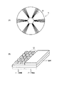
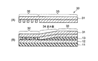
図1(A)はパターンドサーボ媒体1の概略的な平面図であり、図1(B)は図1(A)中のB部分に相当するパターンドサーボ媒体1のサーボ領域2およびデータ領域3を示す斜視図である。サーボ領域とはプリアンブル領域、アドレス領域、バースト領域などを含み、位置情報を示す領域である。図1(B)に示されるように、基板11上に磁性膜12が製膜されている。サーボ領域2は凹凸パターンをなす磁性膜で形成され、データ領域3は平坦な磁性膜で形成されている。サーボ領域2では磁性膜がDC消磁によって一方向に磁化されている。
Hereinafter, although an embodiment of the present invention is described, a prior art is also described for comparison.
1A is a schematic plan view of the patterned servo medium 1, and FIG. 1B is a
パターンドサーボ媒体1の記録再生動作は以下のようにして行われる。すなわち、記録再生ヘッドがサーボ領域2上を通過する際に、凸部をなす磁性膜のみから強い磁界が与えられるため、再生ヘッドが検知する信号の強度は凸部の上で強く、凹部の上で弱くなる。この信号強度の強弱をサーボ信号として処理することによって、媒体上での記録再生ヘッドの位置制御が可能になる。
The recording / reproducing operation of the patterned servo medium 1 is performed as follows. That is, when the recording / reproducing head passes over the
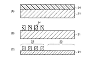
従来、インプリント法によって図1(B)に示す凹凸パターンをなす磁性膜で形成されたサーボ領域2と平坦な磁性膜で形成されたデータ領域3とを有するパターンドサーボ媒体1を製造する場合、図2に示すようなトラック方向に沿う断面を有するインプリントスタンパ20を用いていた。図2に示すインプリントスタンパ20は、スタンパ基板21上に、パターンドサーボ媒体1のサーボ領域2における凹凸パターンの逆パターンとなる凹凸パターンをなすサーボ領域対応部22と、パターンドサーボ媒体1のデータ領域3における平坦な凸部の逆パターンとなる平坦な凹部をなすデータ領域対応部23が形成されたものである。
Conventionally, a patterned servo medium 1 having a
図2に示すインプリントスタンパ20の製造方法を図3(A)〜(C)に示す断面図を参照して説明する。まず、スタンパ基板21上にレジスト24を塗布する(図3(A))。次に、電子線描画により、パターンドサーボ媒体1のサーボ領域2の凹部に対応する部分以外のサーボ領域2の凸部およびデータ領域3に対応する部分のレジスト24に電子線を描画した後、現像してレジストパターン24を形成する(図3(B))。このレジストパターン24をマスクとしてスタンパ基板21をエッチングすることによりレジストパターン24をスタンパ基板21上に転写し、サーボ領域対応部22およびデータ領域対応部23を形成する(図3(C))。
A method for manufacturing the
このように、従来のインプリントスタンパ20を用いる場合、図3(B)の工程においてデータ領域対応部23上の広い面積のレジストに電子線描画する必要があり描画に長時間を要するため、これがインプリントスタンパ20のコスト上昇を招き、ひいてはパターンドサーボ媒体1のコスト上昇を招いていた。
As described above, when the
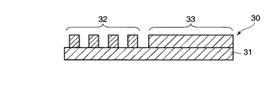
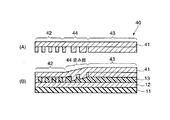
図4に本発明の実施形態において用いられるインプリントスタンパ30の一例をトラック方向に沿う断面で示す。図4のインプリントスタンパ30は、スタンパ基板31上に、パターンドサーボ媒体のサーボ領域における凹凸パターンの逆パターンとなる凹凸パターンをなすサーボ領域対応部32と、サーボ領域対応部32の凸部インプリント面と同じ高さの平坦なインプリント面をなすデータ領域対応部33とを有する。これは、図2に示す従来のインプリントスタンパ20においてデータ領域対応部23が凹部をなすようにエッチングされていたのと異なる。
FIG. 4 shows an example of an
図4に示すインプリントスタンパ30は、図3に示したのと同様な方法で作製することができるが、電子線描画時にデータ領域対応部33上の広い面積のレジストに電子線描画する必要がない。このようにスタンパ製造工程において広い面積を有するデータ領域対応部での描画時間をなくすことができるので、スタンパの製造コストを低減させる。
The
本発明の実施形態においては、図4に示すようなインプリントスタンパ30を用いてインプリント法を実施する。この際、インプリントスタンパ30のサーボ領域対応部32とデータ領域対応部33との間に位置する部分(歪み部)に歪みが生じることを利用して、従来のインプリントスタンパを用いて製造されるものとほぼ同様の構造を有するパターンドサーボ媒体の製造を可能にしている。インプリントスタンパ30は、大きな圧力が加わったときに歪み部が弾性変形するように、金属、合金、金属酸化物、セラミックス、ガラス、半導体、またはこれらの混合物、特にニッケル(Ni)、アルミニウム(Al)、シリコン(Si)、シリコンカーバイド(SiC)、ガラスなどの材料で形成することが好ましい。
In the embodiment of the present invention, an imprint method is performed using an
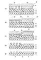
本発明の実施形態に係るパターンドサーボ媒体の製造方法(インプリントプロセス)を、図5(A)〜(E)に示す断面図を参照して概略的に説明する。 A patterned servo medium manufacturing method (imprint process) according to an embodiment of the present invention will be schematically described with reference to cross-sectional views shown in FIGS.
図5(A)に示すように、基板11上に磁性膜12を製膜し、この磁性膜12上にレジスト13を塗布する。レジスト13に対して、図4図示のインプリントスタンパ30を対向させて配置する。
As shown in FIG. 5A, a
図5(B)はインプリント開始時に100atm程度の低圧を加えた状態を示す。基板11上に塗布されたレジスト13はある程度の硬度を持っており、一定値以上の局所的な圧力が加わらないと変形しない。インプリント時にレジスト13にかかる圧力はインプリントスタンパ表面の状態に依存し、一定の圧力下では凸部面積の凹部面積に対する割合が小さい領域ほど凸部にかかる局所的圧力が高くなるため、レジストを容易に変形させることができる。このインプリントスタンパ30ではサーボ領域対応部32の方がデータ領域対応部33よりも凸部の面積比が小さいため、サーボ領域上のレジスト13は変形しやすいが、データ領域上のレジストはほとんど変形しない。このため、インプリントスタンパ30のサーボ領域対応部32のインプリント面がレジスト13中に入り込む深さは深いのに対し、データ領域対応部33のインプリント面はあまりレジスト13中に入り込まない。このとき、インプリントスタンパ30はある程度弾性を持っているため、サーボ領域対応部32とデータ領域対応部33との間の歪み部34(この例ではデータ領域対応部33の端部)に歪みが生じる。
FIG. 5B shows a state where a low pressure of about 100 atm is applied at the start of imprinting. The resist 13 applied on the
図5(C)はインプリント圧力をさらに上げた状態を示している。本発明に係る方法では、1000atm以上の圧力を加えることが好ましい。この状態では、インプリントスタンパ30のサーボ領域対応部32においてほぼ凹部の奥までレジストが達しており、これ以上インプリント深度を深くすることはできない。また、インプリントスタンパ30のサーボ領域対応部32とデータ領域対応部33との間の歪み部34の歪みもほぼ最大に達しており、歪み部34(データ領域対応部33の端部)の最大インプリント深度はサーボ領域対応部32のインプリント深度に近くなっている。
FIG. 5C shows a state where the imprint pressure is further increased. In the method according to the present invention, it is preferable to apply a pressure of 1000 atm or more. In this state, the resist reaches almost the back of the recess in the servo
図5(D)はインプリント終了後にインプリントスタンパ30をレジスト13から離した状態を示している。インプリントスタンパ30のサーボ領域対応部32が押しつけられた領域ではレジスト13に凹凸パターンがほぼ転写され、データ領域対応部33が押しつけられた領域ではレジスト13がほぼそのまま残っている。また、これら2つの領域の間では、レジスト13はトラック方向に沿ってサーボ領域側からデータ領域側へ向かうにつれて厚みが薄い方から厚い方へ変化している。
FIG. 5D shows a state in which the
図5(E)は図5(D)からエッチングすることにより、レジストパターン下の磁性膜12に凹凸パターンを転写した状態を示している。基板11上には、凹凸パターンをなす磁性膜で形成されたサーボ領域2と、平坦な磁性膜で形成されたデータ領域3と、これら2つの領域の間にありトラック方向に沿ってサーボ領域2からデータ領域3へ向かうにつれて厚みが薄い方から厚い方へ変化する部分を含む磁性膜で形成された遷移領域4とが形成されている。ここで、トラック方向に沿う遷移領域4の幅は10〜100μm程度であり、媒体全面に対して遷移領域4が占める面積の割合は小さいため、磁気記録媒体としての機能が損なわれることはない。磁性膜上には保護膜(図示せず)が塗布される。
FIG. 5E shows a state in which the concavo-convex pattern is transferred to the
図5(A)〜(E)を参照して説明したように、本発明の方法によれば、サーボ領域2における凹凸パターンの逆パターンとなる凹凸パターンをなすサーボ領域対応部32と、サーボ領域対応部32の凸部インプリント面と同じ高さの平坦なインプリント面をなすデータ領域対応部33とを有する安価なインプリントスタンパ30を用いて、従来と同様の構造および機能を有するパターンドサーボ媒体を低コストで製造することができる。
As described with reference to FIGS. 5A to 5E, according to the method of the present invention, the servo
なお、本発明に係る磁気記録媒体(パターンドサーボ媒体)においては、サーボ領域2とデータ領域3との間の遷移領域4の面積をできるだけ小さくして記録容量を向上させることが望ましい。遷移領域4の面積を小さくするためには、インプリントスタンパ30のサーボ領域対応部とデータ領域対応部との間の歪み部を意図的に歪みやすくさせることが考えられる。
In the magnetic recording medium (patterned servo medium) according to the present invention, it is desirable to improve the recording capacity by making the area of the transition region 4 between the
たとえば、インプリントスタンパの歪み部をトラック方向に沿って交互に形成されたトラックを横切る複数の平行な線状の凸部で形成し、複数の凸部をトラック方向に沿ってサーボ領域側からデータ領域側へ向かうにつれて幅が短い方から長い方へ変化するように形成してもよい。このようなインプリントスタンパでは歪み部が変形しやすいので、歪み部のトラック方向に沿う幅を短くすることができる。したがって、このインプリントスタンパを用いて作製されるパターンドサーボ媒体では、サーボ領域とデータ領域との間の遷移領域の面積を小さくすることができ、記録容量の向上に寄与する。この効果を図6(A)、(B)と図7(A)、(B)とを対比することにより説明する。 For example, the distorted part of the imprint stamper is formed by a plurality of parallel linear protrusions crossing the tracks formed alternately along the track direction, and the plurality of protrusions are data from the servo area side along the track direction. You may form so that a width | variety may change from the short side to a long side as it goes to the area | region side. In such an imprint stamper, the distorted portion is easily deformed, so that the width of the distorted portion along the track direction can be shortened. Therefore, in the patterned servo medium manufactured using this imprint stamper, the area of the transition region between the servo region and the data region can be reduced, which contributes to the improvement of the recording capacity. This effect will be described by comparing FIGS. 6A and 6B with FIGS. 7A and 7B.
図6(A)、(B)はそれぞれ図4に図示したインプリントスタンパ30のインプリント前の断面図およびインプリント時の断面図である。図5を参照して説明した通り、このインプリントスタンパ30ではデータ領域対応部33の端部が歪み部34となっており、歪みが生じにくい(図6(B)図示)。
6A and 6B are a cross-sectional view of the
一方、図7(A)のインプリントスタンパ40は、スタンプ基板41上で、サーボ領域対応部42とデータ領域対応部43(2つの領域のインプリント面は同じ高さである)との間に、トラック方向に沿って交互に形成されたトラックを横切る複数の平行な線状の凸部を有し、複数の凸部のトラック方向に沿う幅がサーボ領域側からデータ領域側へ向かうにつれて短い方から長い方へ変化するように形成した歪み部44を有し、この歪み部44は変形しやすくなっている。また、この歪み部44では、トラック方向に沿ってサーボ領域側からデータ領域側へ向かうにつれて、凸部面積の凹部面積に対する割合が徐々に大きくなっている。図7(B)に、このインプリントスタンパ40を用いてインプリントしているときの断面図を示す。
On the other hand, the
図6(B)と図7(B)との比較からわかるように、歪み部を変形しやすくしている後者のインプリントスタンパ40では歪み面積を抑えることができる。したがって、このインプリントスタンパ40を用いて作製されるパターンドサーボ媒体では、サーボ領域とデータ領域との間の遷移領域の面積を小さくすることができ、記録容量の向上に寄与する。
As can be seen from a comparison between FIG. 6B and FIG. 7B, the
また、インプリントスタンパの歪み部を、トラック方向に沿ってサーボ領域側からデータ領域側へ向かうにつれてトラックを横切る方向の幅が狭い方から広い方へ変化する、複数の楔状の平面形状をなす凸部で形成してもよい。このようなインプリントスタンパでも、図7と同様に歪み部が変形しやすくなっているので歪み面積を抑えることができる。 Also, the convex portion of the imprint stamper has a plurality of wedge-shaped planar shapes in which the width in the direction crossing the track changes from narrower to wider as it goes from the servo area side to the data area side along the track direction. You may form by a part. Even in such an imprint stamper, the strained area is easily deformed as in FIG. 7, so that the strain area can be suppressed.
以下、本発明の実施例を説明する。
実施例1
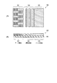
図8(A)に本実施例において用いたインプリントスタンパの平面図を示す。このインプリントスタンパ50は、スタンパ基板上に、パターンドサーボ媒体のサーボ領域における凹凸パターンの逆パターンとなる凹凸パターンをなすサーボ領域対応部52と、サーボ領域対応部52の凸部インプリント面と同じ高さの平坦なインプリント面をなすデータ領域対応部53と、サーボ領域対応部52とデータ領域対応部53との間に位置する歪み部54とを形成したものである。歪み部54は、トラック方向に沿って交互に形成されたトラックを横切る複数の平行な線状の凸部を有し、複数の凸部のトラック方向に沿う幅がサーボ領域側からデータ領域側へ向かうにつれて短い方から長い方へ変化している。このインプリントスタンパ50を用い、図5に示したような方法により、パターンドサーボ媒体を製造することができる。
Examples of the present invention will be described below.
Example 1
FIG. 8A shows a plan view of the imprint stamper used in this embodiment. The
図8(B)に図8(A)のインプリントスタンパを用いて製造されるパターンドサーボ媒体の断面図を示す。このパターンドサーボ媒体60は、基板61上に、凹凸パターンをなす磁性膜で形成されたサーボ領域62と、平坦な磁性膜で形成されたデータ領域63と、これら2つの領域の間に位置する遷移領域64とを有する。この遷移領域64は、トラック方向に沿って交互に形成されたトラックを横切る複数の平行な線状の凸部および凹部をなす磁性膜で形成され、複数の凹部をなす磁性膜はトラック方向に沿ってサーボ領域62からデータ領域63へ向かうにつれて幅が短い方から長い方へ変化し、かつ個々の凹部をなす磁性膜は厚みが薄い方から厚い方へ変化している。
FIG. 8B shows a cross-sectional view of a patterned servo medium manufactured using the imprint stamper shown in FIG. The patterned servo medium 60 is located on a
実施例2
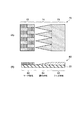
図9(A)に本実施例において用いたインプリントスタンパの平面図を示す。このインプリントスタンパ70は、スタンパ基板上に、パターンドサーボ媒体のサーボ領域における凹凸パターンの逆パターンとなる凹凸パターンをなすサーボ領域対応部72と、サーボ領域対応部72の凸部インプリント面と同じ高さの平坦なインプリント面をなすデータ領域対応部73と、サーボ領域対応部72とデータ領域対応部73との間に位置する歪み部74とを形成したものである。歪み部74は、トラック方向に沿ってサーボ領域側からデータ領域側へ向かうにつれてトラックを横切る方向の幅が狭い方から広い方へ変化する複数の楔状の平面形状をなす凸部で形成されている。このインプリントスタンパ70を用い、図5に示したような方法により、パターンドサーボ媒体を製造することができる。
Example 2
FIG. 9A shows a plan view of the imprint stamper used in this embodiment. The
図9(B)に本実施例において製造されたパターンドサーボ媒体の断面図を示す。このパターンドサーボ媒体80は、基板81上に、凹凸パターンをなす磁性膜で形成されたサーボ領域82と、平坦な磁性膜で形成されたデータ領域83と、これら2つの領域の間に位置する遷移領域84とを有する。この遷移領域84は、トラック方向に沿ってサーボ領域82からデータ領域83へ向かうにつれて、トラックを横切る方向の幅が狭い方から広い方へ変化し(前記歪み部74に対応している)、かつ厚みが薄い方から厚い方へ変化する複数の楔状の平面形状をなす磁性膜で形成されている。
FIG. 9B shows a sectional view of the patterned servo medium manufactured in this embodiment. The patterned
実施例1および実施例2で作製されたパターンドサーボ媒体は、磁気記録再生装置に組み込んで記録再生ヘッドを用いて記録再生できる。 The patterned servo medium manufactured in Example 1 and Example 2 can be recorded and reproduced using a recording / reproducing head incorporated in a magnetic recording / reproducing apparatus.
1…パターンドサーボ媒体、2…サーボ領域、3…データ領域、4…遷移領域、11…基板、12…磁性膜、13…レジスト、20…インプリントスタンパ、21…スタンパ基板、22…サーボ領域対応部、23…データ領域対応部、24…レジスト、30…インプリントスタンパ、31…スタンパ基板、32…サーボ領域対応部、33…データ領域対応部、34…歪み部、40…インプリントスタンパ、41…スタンパ基板、42…サーボ領域対応部、43…データ領域対応部、44…歪み部、50…インプリントスタンパ、52…サーボ領域対応部、53…データ領域対応部、54…歪み部、60…パターンドサーボ媒体、61…基板、62…サーボ領域、63…データ領域、64…遷移領域、70…インプリントスタンパ、72…サーボ領域対応部、73…データ領域対応部、74…歪み部、80…パターンドサーボ媒体、81…基板、82…サーボ領域、83…データ領域、84…遷移領域。
DESCRIPTION OF SYMBOLS 1 ... Patterned servo medium, 2 ... Servo area, 3 ... Data area, 4 ... Transition area, 11 ... Substrate, 12 ... Magnetic film, 13 ... Resist, 20 ... Imprint stamper, 21 ... Stamper substrate, 22 ... Servo area Corresponding part, 23 ... Data area corresponding part, 24 ... Resist, 30 ... Imprint stamper, 31 ... Stamper substrate, 32 ... Servo area corresponding part, 33 ... Data area corresponding part, 34 ... Distorted part, 40 ... Imprint stamper, DESCRIPTION OF
Claims (5)
基板上に磁性膜を製膜した後、レジストを塗布し、
前記インプリントスタンパを前記レジストに押しつけて圧力を加え、前記サーボ領域対応部のインプリント面の前記レジストへの侵入深さが相対的に深く、前記データ領域対応部のインプリント面の前記レジストへの侵入深さが相対的に浅く、前記2つの領域の間に位置する歪み部のインプリント面の前記レジストへの侵入深さがトラック方向に沿ってサーボ領域側からデータ領域側へ向かうにつれて深い方から浅い方へ変化する部分を含むようにインプリントを行い、
前記インプリントスタンパを前記レジストから離し、残存したレジストをマスクとしてエッチングを行うことにより、凹凸パターンをなす磁性膜で形成されたサーボ領域と、平坦な磁性膜で形成されたデータ領域と、前記2つの領域の間にありトラック方向に沿って前記サーボ領域から前記データ領域へ向かうにつれて厚みが薄い方から厚い方へ変化する部分を含む磁性膜で形成された遷移領域とを有する磁気記録媒体を製造することを特徴とする磁気記録媒体の製造方法。 Corresponding servo area corresponding to the concave / convex pattern opposite to the concave / convex pattern in the servo area of the magnetic recording medium, and data area corresponding to the flat imprint surface having the same height as the convex imprint surface of the servo area corresponding portion An imprint stamper having a
After forming a magnetic film on the substrate, apply a resist,
The imprint stamper is pressed against the resist to apply pressure, and the depth of penetration of the imprint surface of the servo area corresponding portion into the resist is relatively deep, and the imprint surface of the data area corresponding portion is applied to the resist. Is relatively shallow, and the depth of penetration of the imprint surface of the strained portion located between the two regions into the resist increases along the track direction from the servo region side to the data region side. Imprint to include the part that changes from one side to the other,
The imprint stamper is separated from the resist, and etching is performed using the remaining resist as a mask, whereby a servo area formed of a magnetic film having a concavo-convex pattern, a data area formed of a flat magnetic film, and the 2 Manufacturing a magnetic recording medium having a transition region formed of a magnetic film including a portion between two regions and changing in thickness from the servo region to the data region along the track direction from the servo region to the data region A method of manufacturing a magnetic recording medium.
Priority Applications (1)
| Application Number | Priority Date | Filing Date | Title |
|---|---|---|---|
| JP2004103850A JP3898704B2 (en) | 2004-03-31 | 2004-03-31 | Magnetic recording medium, manufacturing method thereof, and imprint stamper |
Applications Claiming Priority (1)
| Application Number | Priority Date | Filing Date | Title |
|---|---|---|---|
| JP2004103850A JP3898704B2 (en) | 2004-03-31 | 2004-03-31 | Magnetic recording medium, manufacturing method thereof, and imprint stamper |
Publications (2)
| Publication Number | Publication Date |
|---|---|
| JP2005293662A true JP2005293662A (en) | 2005-10-20 |
| JP3898704B2 JP3898704B2 (en) | 2007-03-28 |
Family
ID=35326441
Family Applications (1)
| Application Number | Title | Priority Date | Filing Date |
|---|---|---|---|
| JP2004103850A Expired - Fee Related JP3898704B2 (en) | 2004-03-31 | 2004-03-31 | Magnetic recording medium, manufacturing method thereof, and imprint stamper |
Country Status (1)
| Country | Link |
|---|---|
| JP (1) | JP3898704B2 (en) |
Cited By (3)
| Publication number | Priority date | Publication date | Assignee | Title |
|---|---|---|---|---|
| JP2010134977A (en) * | 2008-12-02 | 2010-06-17 | Toshiba Storage Device Corp | Magnetic recording medium and magnetic storage device |
| US7969686B2 (en) | 2007-12-26 | 2011-06-28 | Hitachi Global Storage Technologies Netherlands, B.V. | Self-assembly structures used for fabricating patterned magnetic media |
| US8475670B2 (en) | 2011-07-11 | 2013-07-02 | HGST Netherlands B.V. | Method for manufacturing a patterned magnetic media with offset data and servo regions |
-
2004
- 2004-03-31 JP JP2004103850A patent/JP3898704B2/en not_active Expired - Fee Related
Cited By (4)
| Publication number | Priority date | Publication date | Assignee | Title |
|---|---|---|---|---|
| US7969686B2 (en) | 2007-12-26 | 2011-06-28 | Hitachi Global Storage Technologies Netherlands, B.V. | Self-assembly structures used for fabricating patterned magnetic media |
| JP2010134977A (en) * | 2008-12-02 | 2010-06-17 | Toshiba Storage Device Corp | Magnetic recording medium and magnetic storage device |
| US8475670B2 (en) | 2011-07-11 | 2013-07-02 | HGST Netherlands B.V. | Method for manufacturing a patterned magnetic media with offset data and servo regions |
| US9251835B2 (en) | 2011-07-11 | 2016-02-02 | HGST Netherlands B.V. | Patterned magnetic media with offset data and servo regions |
Also Published As
| Publication number | Publication date |
|---|---|
| JP3898704B2 (en) | 2007-03-28 |
Similar Documents
| Publication | Publication Date | Title |
|---|---|---|
| CN100377210C (en) | Magnetic recording medium, manufacturing method thereof, and magnetic recording device | |
| JP3343326B2 (en) | Master information carrier | |
| US6703099B2 (en) | Perpendicular magnetic recording media with patterned soft magnetic underlayer | |
| JP4703609B2 (en) | Method for manufacturing magnetic recording medium | |
| JP2010033635A (en) | Method of manufacturing magnetic recording medium | |
| US6858328B1 (en) | Master information support | |
| JP4008933B2 (en) | Magnetic recording medium, method for manufacturing the same, and magnetic recording apparatus | |
| JP3898704B2 (en) | Magnetic recording medium, manufacturing method thereof, and imprint stamper | |
| JP5033003B2 (en) | Mold structure, imprint method using the same, magnetic recording medium and method for manufacturing the same | |
| JP5121902B2 (en) | Magnetic recording medium | |
| US20080014456A1 (en) | Process of producing master carrier for magnetic transfer | |
| JP2001312819A (en) | Magnetic recording method for perpendicular magnetic recording medium using master information carrier | |
| KR101498172B1 (en) | Servo master that self-transfers a servo pattern to a magnetic recording medium and magnetic transfer method using the same | |
| JP2005071467A (en) | Magnetic recording medium and manufacturing method thereof | |
| JP3934890B2 (en) | Initializing method of magnetic recording medium | |
| JP3646990B2 (en) | Master information magnetic recording apparatus and method of manufacturing magnetic recording medium | |
| US7368186B2 (en) | Master carrier for magnetic transfer | |
| JP5829671B2 (en) | Method for producing a master recording medium | |
| JP2008287805A (en) | Mold structure and imprint method using the same | |
| JP2006338792A (en) | Method of forming uneven pattern, and manufacturing method of magnetic recording medium | |
| JP2010123158A (en) | Magnetic recording medium, method of manufacturing magnetic recording medium and magnetic recording and playback device | |
| JP2011014198A (en) | Method of manufacturing master information carrier for magnetic transfer, and method of manufacturing magnetic recording medium | |
| JP2004127494A (en) | Master carrier for magnetic transfer | |
| JP2005353170A (en) | Magnetic recording medium manufacturing method and magnetic recording / reproducing apparatus | |
| JP2006099904A (en) | Magnetic recording medium manufacturing method and magnetic recording medium manufacturing apparatus |
Legal Events
| Date | Code | Title | Description |
|---|---|---|---|
| A977 | Report on retrieval |
Effective date: 20060907 Free format text: JAPANESE INTERMEDIATE CODE: A971007 |
|
| A131 | Notification of reasons for refusal |
Free format text: JAPANESE INTERMEDIATE CODE: A131 Effective date: 20060919 |
|
| A521 | Written amendment |
Effective date: 20061117 Free format text: JAPANESE INTERMEDIATE CODE: A523 |
|
| TRDD | Decision of grant or rejection written | ||
| A01 | Written decision to grant a patent or to grant a registration (utility model) |
Free format text: JAPANESE INTERMEDIATE CODE: A01 Effective date: 20061219 |
|
| A61 | First payment of annual fees (during grant procedure) |
Free format text: JAPANESE INTERMEDIATE CODE: A61 Effective date: 20061221 |
|
| LAPS | Cancellation because of no payment of annual fees |