JP2005293352A - Control device, control method, and control program - Google Patents
Control device, control method, and control program Download PDFInfo
- Publication number
- JP2005293352A JP2005293352A JP2004109052A JP2004109052A JP2005293352A JP 2005293352 A JP2005293352 A JP 2005293352A JP 2004109052 A JP2004109052 A JP 2004109052A JP 2004109052 A JP2004109052 A JP 2004109052A JP 2005293352 A JP2005293352 A JP 2005293352A
- Authority
- JP
- Japan
- Prior art keywords
- control
- screen
- control screen
- service
- screen component
- Prior art date
- Legal status (The legal status is an assumption and is not a legal conclusion. Google has not performed a legal analysis and makes no representation as to the accuracy of the status listed.)
- Pending
Links
- 238000000034 method Methods 0.000 title claims abstract description 20
- 238000001514 detection method Methods 0.000 claims abstract description 8
- 230000006870 function Effects 0.000 claims description 28
- 238000010586 diagram Methods 0.000 description 16
- 230000009471 action Effects 0.000 description 14
- 230000008569 process Effects 0.000 description 8
- 230000004913 activation Effects 0.000 description 2
- 230000007704 transition Effects 0.000 description 2
- 230000005540 biological transmission Effects 0.000 description 1
- 230000008859 change Effects 0.000 description 1
- 230000002542 deteriorative effect Effects 0.000 description 1
- 230000001771 impaired effect Effects 0.000 description 1
- 230000002093 peripheral effect Effects 0.000 description 1
- 239000004065 semiconductor Substances 0.000 description 1
Images


Classifications
-
- H—ELECTRICITY
- H04—ELECTRIC COMMUNICATION TECHNIQUE
- H04N—PICTORIAL COMMUNICATION, e.g. TELEVISION
- H04N5/00—Details of television systems
- H04N5/76—Television signal recording
- H04N5/765—Interface circuits between an apparatus for recording and another apparatus
-
- H—ELECTRICITY
- H04—ELECTRIC COMMUNICATION TECHNIQUE
- H04L—TRANSMISSION OF DIGITAL INFORMATION, e.g. TELEGRAPHIC COMMUNICATION
- H04L41/00—Arrangements for maintenance, administration or management of data switching networks, e.g. of packet switching networks
- H04L41/12—Discovery or management of network topologies
-
- H—ELECTRICITY
- H04—ELECTRIC COMMUNICATION TECHNIQUE
- H04L—TRANSMISSION OF DIGITAL INFORMATION, e.g. TELEGRAPHIC COMMUNICATION
- H04L67/00—Network arrangements or protocols for supporting network services or applications
- H04L67/01—Protocols
- H04L67/12—Protocols specially adapted for proprietary or special-purpose networking environments, e.g. medical networks, sensor networks, networks in vehicles or remote metering networks
- H04L67/125—Protocols specially adapted for proprietary or special-purpose networking environments, e.g. medical networks, sensor networks, networks in vehicles or remote metering networks involving control of end-device applications over a network
-
- H—ELECTRICITY
- H04—ELECTRIC COMMUNICATION TECHNIQUE
- H04L—TRANSMISSION OF DIGITAL INFORMATION, e.g. TELEGRAPHIC COMMUNICATION
- H04L67/00—Network arrangements or protocols for supporting network services or applications
- H04L67/50—Network services
- H04L67/75—Indicating network or usage conditions on the user display
-
- H—ELECTRICITY
- H04—ELECTRIC COMMUNICATION TECHNIQUE
- H04N—PICTORIAL COMMUNICATION, e.g. TELEVISION
- H04N5/00—Details of television systems
- H04N5/76—Television signal recording
- H04N5/765—Interface circuits between an apparatus for recording and another apparatus
- H04N5/775—Interface circuits between an apparatus for recording and another apparatus between a recording apparatus and a television receiver
Landscapes
- Engineering & Computer Science (AREA)
- Signal Processing (AREA)
- Computer Networks & Wireless Communication (AREA)
- Health & Medical Sciences (AREA)
- Computing Systems (AREA)
- General Health & Medical Sciences (AREA)
- Medical Informatics (AREA)
- Multimedia (AREA)
- User Interface Of Digital Computer (AREA)
- Computer And Data Communications (AREA)
- Stored Programmes (AREA)
Abstract
【課題】 ネットワークに接続される種々のデバイスの操作を容易にする制御装置、制御方法及び制御プログラムを提供する。
【解決手段】 制御画面部品が格納されたメモリと、ネットワークに接続されているデバイスが提供するサービスを検出する検出手段と、検出された前記サービスに関連付けられた前記制御画面部品を選択可能に画面表示する制御画面表示手段と、画面表示された前記制御画面部品の選択を受け付ける制御選択手段と、選択された前記制御画面部品に関連付けられた前記サービスを前記デバイスに提供させる制御手段と、を備えることを特徴とする制御装置。
【選択図】 図1PROBLEM TO BE SOLVED: To provide a control device, a control method, and a control program for facilitating operation of various devices connected to a network.
SOLUTION: Memory in which control screen components are stored, detection means for detecting a service provided by a device connected to a network, and a screen capable of selecting the control screen component associated with the detected service Control screen display means for displaying; control selection means for accepting selection of the control screen part displayed on the screen; and control means for providing the device with the service associated with the selected control screen part. A control device characterized by that.
[Selection] Figure 1
Description
本発明は、制御装置、制御方法及び制御プログラムに関し、特にネットワークで接続された種々のデバイスを統合的に制御する装置のHMI(Human Machine Interface)に関する。 The present invention relates to a control apparatus, a control method, and a control program, and more particularly, to an HMI (Human Machine Interface) of an apparatus that integrally controls various devices connected via a network.
一般に、コンピュータに周辺機器をセットアップして利用可能な状態にするためには、エンドユーザ自身が複雑な設定を行うことが要求されるため、コンピュータに関する基本的な知識が必要になる。こうした問題を解決する手段の1つとしてUPnP(Universal Plug and Play)が注目されている。多数のUPnPデバイスで1つのネットワークが構成されるようになると、例えばネットワークに接続されたテレビは、テレビ放送の表示以外に、ファイルサーバに格納されている画像データの表示等のさまざまな用途に利用できるようになる。またネットワーク内では、デスクトップPC(Personal Computer)、テレビのリモートコントローラ等で構成されるコントロールポイントによってあらゆるデバイスを制御できるようになるほか、コントロールポイントで複数のデバイスを連携させるようなプログラムを実行することによって単独のデバイスでは実現できない機能を実現することも可能になる。 Generally, in order to set up a peripheral device in a computer and make it usable, end users themselves are required to perform complicated settings, and thus basic knowledge about the computer is required. UPnP (Universal Plug and Play) is attracting attention as one means for solving such problems. When a single network is configured with a large number of UPnP devices, for example, a television connected to the network is used for various purposes such as displaying image data stored in a file server in addition to displaying a television broadcast. become able to. In the network, all devices can be controlled by a control point consisting of a desktop PC (Personal Computer), a TV remote controller, etc., and a program that links multiple devices at the control point is executed. This makes it possible to realize functions that cannot be realized by a single device.
本発明は、ネットワークに接続される種々のデバイスの操作を容易にする制御装置、制御方法及び制御プログラムを提供することを目的とする。 An object of the present invention is to provide a control device, a control method, and a control program that facilitate the operation of various devices connected to a network.
上記目的を達成するための制御装置は、制御画面部品が格納されたメモリと、ネットワークに接続されているデバイスが提供するサービスを検出する検出手段と、検出された前記サービスに関連付けられた前記制御画面部品を選択可能に画面表示する制御画面表示手段と、画面表示された前記制御画面部品の選択を受け付ける制御選択手段と、選択された前記制御画面部品に関連付けられた前記サービスを前記デバイスに提供させる制御手段と、を備える。制御装置が画面表示した制御画面部品をユーザが選択した場合に、選択された制御画面部品に関連付けられたサービスを、そのサービスをネットワーク内で提供するデバイスに制御装置の制御下で提供させることにより、ユーザは制御装置を介して種々のデバイスが提供するサービスを受けることができる。ネットワークに接続されているデバイスが提供するサービスを制御装置が検出し、制御装置に予め記憶されている制御画面部品のうち検出したサービスに関連するものを制御装置が選択可能に画面表示することにより、ネットワークに新たにデバイスを接続するときにそのデバイスを制御するための制御画面部品を制御装置に入力する必要が無くなる。ネットワークに新たにデバイスを接続するときにそのデバイスを制御するための制御画面部品を制御装置に入力する必要が無くなると、ネットワークに接続される種々のデバイスの操作が容易になる。 The control device for achieving the above object includes a memory in which control screen components are stored, detection means for detecting a service provided by a device connected to a network, and the control associated with the detected service. Control screen display means for displaying screen parts in a selectable manner, control selection means for accepting selection of the control screen parts displayed on the screen, and providing the service associated with the selected control screen parts to the device Control means. When the user selects a control screen component displayed on the screen by the control device, by causing the device associated with the selected control screen component to be provided within the network under the control of the control device. The user can receive services provided by various devices via the control device. By detecting a service provided by a device connected to the network by the control device, and displaying on the screen that the control device can select a control screen component stored in advance in the control device in relation to the detected service. When a device is newly connected to the network, it is not necessary to input a control screen component for controlling the device to the control device. When it is not necessary to input a control screen component for controlling a new device to the network when the device is newly connected to the network, operations of various devices connected to the network are facilitated.
前記メモリには、デバイス制御プロトコルで規定された複数の前記サービスと複数の前記制御画面部品が互いに関連付けられて記憶され、前記検出手段は、前記ネットワークに接続されている前記デバイスから当該デバイスを制御するための制御情報を取得し、前記制御手段は、取得した前記制御情報に基づいて前記デバイスを制御し、前記デバイスに前記サービスを提供させることが望ましい。デバイス制御プロトコルで規定されたサービス毎に制御画面部品を予め用意しておくことにより、制御装置の汎用性を向上させることができる。また、デバイスにサービスを提供させるための情報(制御情報)を制御装置がデバイスから取得することにより、そのような情報をユーザが制御装置に入力する必要が無くなる。 The memory stores a plurality of the services defined by a device control protocol and a plurality of the control screen components in association with each other, and the detection unit controls the device from the devices connected to the network. It is preferable that the control information for acquiring the control information is acquired, and the control unit controls the device based on the acquired control information and causes the device to provide the service. By preparing control screen parts in advance for each service defined by the device control protocol, the versatility of the control device can be improved. Further, when the control device acquires information (control information) for providing a service to the device from the device, it is not necessary for the user to input such information to the control device.
前記制御画面表示手段は、複数の前記デバイスが提供する互いに異なるサービスの組み合わせで実現される機能に関連付けられた前記制御画面部品を選択可能に画面表示し、前記制御手段は、選択された前記制御画面部品に関連付けられた前記機能を実現する複数の前記サービスを複数の前記デバイスに提供させることが望ましい。複数のデバイスが提供する互いに異なるサービスを組み合わせることによって実現される機能に応じて制御装置に制御画面部品を予め記憶しておき、選択された制御画面部品に応じて制御装置が複数のデバイスにそれぞれサービスを提供させることにより、個々のデバイス単独では実現不可能な機能をユーザは制御装置を介して容易に利用できるようになる。 The control screen display means displays the control screen component associated with a function realized by a combination of different services provided by a plurality of the devices in a selectable manner, and the control means displays the selected control. It is desirable that a plurality of the devices that realize the function associated with the screen component be provided to a plurality of the devices. Control screen components are stored in advance in the control device in accordance with functions realized by combining different services provided by a plurality of devices, and the control device is assigned to the plurality of devices in accordance with the selected control screen components. By providing the service, the user can easily use functions that cannot be realized by the individual device alone via the control device.
前記メモリには、デバイス制御プロトコルで規定された複数の前記サービスに前記機能が関連付けて記憶されていることが望ましい。デバイス制御プロトコルで規定されたサービスに応じた機能を予め用意しておくことにより、制御装置の汎用性を向上させることができる。 In the memory, it is preferable that the function is stored in association with a plurality of the services defined by a device control protocol. The versatility of the control device can be improved by preparing in advance a function corresponding to the service defined by the device control protocol.
目的を選択可能に画面表示する目的選択画面表示手段と、画面表示された前記目的の選択を受け付ける目的選択手段とをさらに備え、前記制御画面表示手段は、複数の前記制御画面部品のうち選択された前記目的に関連付けられた前記制御画面部品を選択可能に画面表示することが望ましい。ユーザに目的を選択させ、選択された目的に応じた制御画面表示部品を制御装置が選択的に画面表示することにより、ネットワークに接続されるデバイスの数が多くなっても、ユーザの目的に適合していない制御画面部品が画面表示されることによって制御装置の操作性が悪化することを防止できる。 It further comprises purpose selection screen display means for displaying a purpose selectably and a purpose selection means for accepting selection of the purpose displayed on the screen, wherein the control screen display means is selected from among the plurality of control screen components. It is desirable to display the control screen component associated with the purpose in a selectable manner. The user selects the purpose, and the control device selectively displays the control screen display component according to the selected purpose, so that even if the number of devices connected to the network increases, the user's purpose is met. It is possible to prevent the operability of the control device from deteriorating due to the display of the control screen parts that have not been displayed.
前記メモリには、デバイス制御プロトコルで規定された複数の前記サービスに前記目的が関連付けて記憶されていることが望ましい。デバイス制御プロトコルで規定されたサービスに応じて達成可能な目的を予め用意しておくことにより、制御装置の汎用性を向上させることができる。 In the memory, it is preferable that the object is stored in association with a plurality of the services defined by a device control protocol. By preparing in advance the objectives that can be achieved according to the service defined by the device control protocol, the versatility of the control device can be improved.
上記目的を達成するための制御方法は、ネットワークに接続されているデバイスが提供するサービスを検出するステップと、予め記憶されている制御画面部品のうち、検出された前記サービスに関連付けられた前記制御画面部品を選択可能に画面表示するステップと、画面表示された前記制御画面部品の選択を受け付けるステップと、選択された前記制御画面部品に関連付けられた前記サービスを前記デバイスに提供させるステップと、を含む。 A control method for achieving the above object includes a step of detecting a service provided by a device connected to a network, and the control associated with the detected service among control screen components stored in advance. Screen-selectively displaying a screen component, receiving a selection of the control screen component displayed on the screen, and causing the device to provide the service associated with the selected control screen component. Including.
上記目的を達成するための制御プログラムは、ネットワークに接続されているデバイスが提供するサービスを検出する検出手段と、予め記憶されている制御画面部品のうち、検出された前記サービスに関連付けられた前記制御画面部品を選択可能に画面表示する制御画面表示手段と、画面表示された前記制御画面部品の選択を受け付ける制御選択手段と、選択された前記制御画面部品に関連付けられた前記サービスを前記デバイスに提供させる制御手段と、としてコンピュータを機能させる。 A control program for achieving the above object includes: a detecting unit that detects a service provided by a device connected to a network; and the control screen component stored in advance, the control program associated with the detected service Control screen display means for selectively displaying control screen parts, control selection means for receiving selection of the control screen parts displayed on the screen, and the service associated with the selected control screen parts to the device The computer functions as a control means to be provided.
上記目的を達成するための記録媒体には、ネットワークに接続されているデバイスが提供するサービスを検出する検出手段と、予め記憶されている制御画面部品のうち、検出された前記サービスに関連付けられた前記制御画面部品を選択可能に画面表示する制御画面表示手段と、画面表示された前記制御画面部品の選択を受け付ける制御選択手段と、選択された前記制御画面部品に関連付けられた前記サービスを前記デバイスに提供させる制御手段と、としてコンピュータを機能させる制御プログラムが記録される。 The recording medium for achieving the above object includes detection means for detecting a service provided by a device connected to a network, and control screen components stored in advance, which are associated with the detected service. Control screen display means for displaying the control screen parts in a selectable manner; control selection means for receiving selection of the control screen parts displayed on the screen; and the service associated with the selected control screen parts as the device And a control program for causing the computer to function as the control means to be provided.
尚、本発明に備わる複数の手段の各機能は、構成自体で機能が特定されるハードウェア資源、プログラムにより機能が特定されるハードウェア資源、又はそれらの組み合わせにより実現される。また、これら複数の手段の各機能は、各々が物理的に互いに独立したハードウェア資源で実現されるものに限定されない。 The functions of the plurality of means provided in the present invention are realized by hardware resources whose functions are specified by the configuration itself, hardware resources whose functions are specified by a program, or a combination thereof. The functions of the plurality of means are not limited to those realized by hardware resources that are physically independent of each other.
以下、本発明の制御装置、制御方法及び制御プログラムについて、発明を実施するための最良の形態を図面に基づいて説明する。
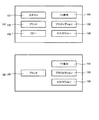
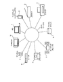
本発明の実施例による制御装置は、図2に示すPC(パーソナルコンピュータ)1等で構成されるUPnPコントロールポイントである。本実施例では、PC1を例にして説明するが、本発明の制御装置はワイヤレスハンドヘルドPC2、図示しない携帯電話等で構成することもできる。本実施例の制御プログラムは、PC1等のUPnPコントロールポイントで実行される。UPnPネットワーク11に接続されるUPnPデバイスとしては、スキャナ3、プリンタ4、ファイルサーバ5、オーディオプレーヤ6、プロジェクタ7、ルータ8、ディジタルカメラ9、TV(Television)モニタ10等がある。
The best mode for carrying out the present invention will be described below with reference to the drawings for a control device, a control method, and a control program of the present invention.
The control device according to the embodiment of the present invention is a UPnP control point constituted by a PC (personal computer) 1 shown in FIG. In the present embodiment, the PC 1 will be described as an example. However, the control device of the present invention can be configured by a wireless handheld PC 2, a mobile phone (not shown), or the like. The control program of this embodiment is executed at a UPnP control point such as PC1. Examples of UPnP devices connected to the UPnP network 11 include a
図3は、制御装置としてのPC1のハードウェアを示すブロック図である。PC1は、CPU20、RAM21、ハードディスク装置(HDD)22、外部インターフェイス23、ROM24、表示部25及び操作部26を備える。CPU20は、制御プログラムを実行し、UPnPデバイス及びUPnPデバイスにサービスを提供させるための制御情報を検出する検出処理、検出されたサービスに関連付けられた制御画面部品を選択可能に画面表示する制御画面表示処理、画面表示された制御画面部品の選択を受け付ける制御選択処理、選択された制御画面部品に応じたサービスをUPnPデバイスに提供させる制御処理、複数のデバイスにより実現される目的を選択可能に画面表示する目的選択画面表示処理等を行い、UPnPデバイスの制御を行う。制御画面部品とは、マウスなどのポインティングデバイスにより操作され、所定のプログラムを呼び出したり、パラメータを変更したりする操作を対話的に受け付けるための画面構成要素であり、例えば、ボタン、ドロップダウンリストボックス等である。
FIG. 3 is a block diagram showing hardware of the PC 1 as a control device. The PC 1 includes a
ROM24は、CPU20が初期動作するためのプログラムを記憶したメモリである。RAM21は、制御プログラムと制御プログラムがアクセスするデータを一時的に記憶するメモリである。請求項に記載のメモリとしてのHDD22は、制御プログラム、制御プログラムがアクセスする各種のデータなどを記憶する外部記憶装置である。尚、制御プログラムはフラッシュメモリ等の半導体メモリに記憶しておいてもよい。
The
外部インターフェイス23は、PC1と外部機器を接続するインターフェイスであって、具体的には例えばLANカード等で構成される。表示部25は、CRT、LCD、ディスプレイコントローラ等により構成され、制御画面部品等の画面構成部品で構成されるGUI(Graphical User Interface)画面を表示する。制御選択手段及び目的選択手段としての操作部26は、キーボード、ポインティングデバイス(マウス、タブット等)により構成される。
The
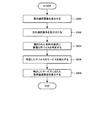
図4は、コントロールポイントとして作動するPC1によってUPnPデバイスを制御する処理の流れを説明するフローチャートである。図4に示す処理はPC1が制御プログラムを実行することによって行われる。
UPnPデバイスは、ネットワークに接続されると、ネットワーク上で定期的にSSDP(Simple Service Discovery Protocol)を使って自己の存在を他のUPnPデバイスに告知する。SSDPは、HTTP(Hypertext Transfer Protocol)ヘッダを拡張したマルチキャスト・ディスカバリ・プロトコルで、ディスカバリ・パケットには、XML(eXtensible Markup Language)形式で記述されたDDD(Device Description Document)へのリンクが含まれている。DDDには、デバイスタイプ、メーカ名、モデル名等の他に、UPnPにより定義されたSDD(Service Description Document)を参照するためのURLが記述されている。PC1はSSDPによりUPnPデバイスを検出し、検出したデバイスのDDDを取得する(S100)。PC1はSSDPにより他のUPnPデバイスの接続状態を問い合わせてUPnPデバイスを主体的に検出することもできる。
FIG. 4 is a flowchart for explaining the flow of processing for controlling the UPnP device by the PC 1 operating as a control point. The process shown in FIG. 4 is performed by the PC 1 executing a control program.
When a UPnP device is connected to a network, it periodically notifies its presence to other UPnP devices using SSDP (Simple Service Discovery Protocol) on the network. SSDP is a multicast discovery protocol that expands the HTTP (Hypertext Transfer Protocol) header. The discovery packet includes a link to a DDD (Device Description Document) described in XML (eXtensible Markup Language) format. Yes. In addition to the device type, manufacturer name, model name, etc., the DDD describes a URL for referring to an SDD (Service Description Document) defined by UPnP. The PC 1 detects the UPnP device by SSDP and acquires the DDD of the detected device (S100). The PC 1 can also detect UPnP devices by inquiring the connection status of other UPnP devices by SSDP.
次にPC1はDDDに記述されたURLを参照し、デバイスが提供するサービスをXML形式で詳しく記述したSDDを取得する(S102)。PC1はSDDを取得することにより、UPnPネットワーク11に接続されたデバイスが提供するサービスを判別し、デバイスにサービスを提供させるための制御情報としてのアクション及び状態変数に関する情報を取得することができる。
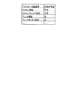
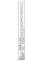
次にPC1はSDDに基づいて図5に示すサービス管理テーブルを更新する(S104)。サービス管理テーブルは、DCP(Device Control Protocol)で規定されている全サービスについて、UPnPネットワーク11に実際に接続されているUPnPデバイスの提供状態を管理するためのデータである。サービス管理テーブルには、DCPで規定されているサービスのアクション及び状態変数についてそれぞれ利用の可否と、各サービスを利用するにあたって最低限必要となる情報(メッセージのあて先等)が記述される。
Next, the PC 1 refers to the URL described in the DDD, and acquires the SDD in which the service provided by the device is described in detail in the XML format (S102). By acquiring the SDD, the PC 1 can determine a service provided by a device connected to the UPnP network 11, and can acquire information on an action and a state variable as control information for causing the device to provide the service.
Next, the PC 1 updates the service management table shown in FIG. 5 based on the SDD (S104). The service management table is data for managing the provision status of UPnP devices that are actually connected to the UPnP network 11 for all services defined by DCP (Device Control Protocol). In the service management table, whether or not each service action and state variable defined in the DCP can be used, and information necessary for using each service (such as a message destination) are described.
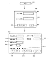
次にPC1はサービス管理テーブル及び画面管理テーブルを参照し、UPnPネットワーク11に接続されているデバイスが提供するサービスに応じた制御画面部品を選択可能に表示部25の画面に例えば図1に示すように表示する(S106)。各ボタン107、102、103、104、105、106は、デバイスの接続状態に応じて選択可能なもののみを表示しても良く、又、対応するデバイスが接続されていないために選択できないボタンについては、グレー表示をし、ポインティングデバイスによる選択ができないように表示しても良い。図1(A)はUPnPネットワーク11が図2に示す状態にあるときに表示部25に表示される制御画面を例示し、図1(B)はUPnPネットワーク11が図2に示すスキャナ3が取り外された状態にあるときに表示部25に表示される制御画面を例示している。
Next, the PC 1 refers to the service management table and the screen management table, and can select a control screen component corresponding to the service provided by the device connected to the UPnP network 11 on the screen of the
図6は、画面管理テーブルを示す模式図である。画面管理テーブルは、DCPで規定されているアクション及び状態変数を利用することによって制御可能なサービスの利用要求等をユーザから受け付けるための制御画面部品を管理するテーブルであって、制御プログラムの一部としてHDD22にあらかじめ記憶されている。画面管理テーブルの各レコードは、各制御画面部品について、制御画面部品のリソースデータにアクセスするための識別子(ラベル、ポインタ等)と、画面上の表示位置と、選択されたときに起動するモジュールを呼び出すための情報(ラベル、プログラムポインタ等)と、選択されたときに起動するプログラムが利用するアクション及び状態変数とを関連付けている。PC1は起動モジュールが利用する全てのアクション及び状態変数がサービス管理テーブルで「利用可」になっている制御画面部品を特定し、特定した制御画面部品を表示部25の画面に選択可能に表示する。尚、制御画面部品は画面管理テーブル及びサービス管理テーブルを介してUPnPデバイスが提供するサービスに関連付けられている。
FIG. 6 is a schematic diagram showing a screen management table. The screen management table is a table for managing control screen components for accepting, from a user, a service use request that can be controlled by using actions and state variables defined in DCP, and is a part of the control program Is stored in advance in the
次に、PC1は、制御画面部品がマウスによるクリック等によって選択されると、選択された制御画面部品に関連付けられたモジュールを、画面管理テーブルを参照して呼び出す。例えば、図1に示すスキャンボタン107が選択されると、制御プログラムのメインモジュールは、画面管理テーブルに記述されたラベルを用いて、スキャナ3のスキャンサービスを制御するためのスキャン制御モジュールを呼び出す。スキャン制御モジュールは、アクション及び状態変数を含むメッセージを所定のシーケンスでスキャナ3に送信し、UPnPスキャナ3をPC1の制御下で作動させる。アクション及び状態変数を含むメッセージはS102で取得したSDDに記述されたあて先に送信される。また例えば、プリントボタン102が選択されると、制御プログラムのメインモジュールは、画面管理テーブルに記述されたラベルを用いて、プリンタ4を制御するためのプリント制御モジュールを呼び出す。プリント制御モジュールは、アクション及び状態変数を含むメッセージを所定のシーケンスでプリンタ4に送信し、プリンタ4をPC1の制御下で作動させる。尚、スキャン要求、プリント要求等の各種のメッセージは、1回で送信してもよいし、複数回に分けて送信してもよい。例えばメッセージとDCPで規定されるアクションとを一対一に対応させてPC1と制御対象デバイスとの間で送受信を繰り返し、1つのサービスを制御することができる。
Next, when the control screen component is selected by clicking with the mouse or the like, the PC 1 calls a module associated with the selected control screen component with reference to the screen management table. For example, when the
同一のサービスを提供する複数のUPnPデバイスがPC1に接続されている場合、PC1はそれらのUPnPデバイスの1つを選択するための画面を表示部25の画面に表示してもよい。具体的には例えば、図7に示す画面200、図8に示す画面300を表示し、ドロップダウンリストボックス201、301、302の操作によって選択されたデバイスをボタン107、103が選択された場合に実行されるモジュールが通信する対象デバイスとして特定する。より具体的には例えば、特定された対象デバイスのSDDに記述されている、あるサービスに属するアクションを呼び出すためのURLを、当該アクションを呼び出すメッセージを送信するあて先として設定する。尚、アクション及び状態変数を指定するメッセージを制御対象デバイスに送信するためのあて先は請求項に記載の制御情報に相当する。
When a plurality of UPnP devices providing the same service are connected to the PC 1, the PC 1 may display a screen for selecting one of those UPnP devices on the screen of the
また、PC1は制御画面部品で構成されるメニュー画面を階層的に表示しても良い。具体的には例えば、PC1は図7及び図8に示す画面210、画面310を表示し、制御対象デバイスの操作を対話的に受け付けても良い。画面210、310で表示される制御画面部品211、212、213、312、313、314、317は状態変数の変更操作に用いられるドロップダウンリストボックスである。制御画面部品315は状態変数の変更操作に用いられるラジオボタンである。画面210、310で表示される制御画面部品214、215、216、318、319、320はアクションの呼び出し操作に用いられるボタンである。
Further, the PC 1 may hierarchically display a menu screen composed of control screen components. Specifically, for example, the PC 1 may display the
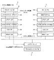
図9は、スキャナ3をPC1の制御下で作動させる処理を具体的に説明するための模式図である。図1(A)に示す制御画面でスキャンボタン107がクリックによって選択されると、制御プログラム101のメインモジュールは、画面管理テーブルに記述された起動モジュールのラベルを用いて、スキャナ3が提供するスキャンサービスを制御するためのスキャン制御モジュールを呼び出す。呼び出されたスキャン制御モジュールは、UPnPコア33、HTTP34、TCP/IP35及びEthernet37(Ethernetは登録商標である。)を介してスキャン要求をUPnPスキャナドライバ32に送信する(S171)。スキャン要求では、スキャンしたデータの出力先となるスキャンボックスのURL、解像度等の各種パラメータが指定される。次に、UPnPスキャナドライバ32によりスキャン要求が受信されると、スキャン要求に基づいてUPnPスキャナドライバ32によってスキャナ3のハードウェア31が制御される(S172)。UPnPスキャナドライバ32は原稿を読み取って得られるスキャンデータを取得すると(S173)、スキャンデータをJpeg画像データに変換する。次に、UPnPスキャナドライバ32は、スキャン要求で指定されたURLにUPnPコア33、HTTP34、TCP/IP35及びEthernet37を介してJpeg画像データを送信する(S174)。図9では、ファイルサーバ5にJpeg画像データがポストされる例を示している。
FIG. 9 is a schematic diagram for specifically explaining a process of operating the
次に、複数のデバイスが提供する互いに異なるサービスの組み合わせで実現される機能について説明する。このような機能としては、スキャナ3が読み取った画像をプリンタ4が印刷するコピー機能、ファイルサーバ5又はディジタルカメラ9に一定時間間隔で連続的に出力させる画像をTVモニタ10、プロジェクタ7、ディジタルピクチャフレーム等で表示するスライドショー機能、ファイルサーバ5からランダムな順序で出力させる音楽データをオーディオプレーヤ6で再生させる音楽再生機能等がある。
Next, functions realized by a combination of different services provided by a plurality of devices will be described. As such a function, a copy function in which an image read by the
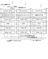
図10は、制御装置としてのPC1が、スキャナ3に読み取らせた画像をプリンタ4で印刷させるコピー機能を具体的に説明するための模式図である。
図1(A)に示す制御画面でコピーボタン103がクリックによって選択されると、制御プログラム101のメインモジュールは、画面管理テーブルに記述された起動モジュールのラベルを用いて、スキャナ3のスキャンサービス及びプリンタ4のプリントサービスを制御するためのコピー制御モジュールを呼び出す。呼び出されたコピー制御モジュールは、UPnPコア33、HTTP34、TCP/IP35及びEthernet37を介してコピー要求をプリンタ4のUPnPプリンタドライバ42に送信する(S161)。コピー要求を受信したUPnPプリンタドライバ42は、読み取った画像データのポスト先としてのスキャンボックスのURLをUPnPコア33、HTTP34、TCP/IP35及びEthernet37を介してPC1の制御プログラム101に送信する(S162)。次に、制御プログラム101は、UPnPプリンタドライバ42から指定されたスキャンボックスのURLを指定したスキャン要求を、UPnPコア33、HTTP34、TCP/IP35及びEthernet37を介してスキャナ3のUPnPスキャナ3に送信する(S163)。UPnPスキャナドライバ32によりスキャン要求が受信されると、スキャン要求に基づいてUPnPスキャナドライバ32によってスキャナ3のハードウェアが制御される(S164)。UPnPスキャナドライバ32はスキャンデータを取得すると(S165)、スキャンデータをJpeg画像データに変換する。次に、UPnPスキャナドライバ32は、スキャン要求で指定されたURLのスキャンボックスにUPnPコア33、HTTP34、TCP/IP35及びEthernet37を介してJpeg画像データを送信する(S166)。図10では、プリンタ4自体がスキャンボックスとして指定されている例を示している。尚、PC1、ファイルサーバ5等の他のデバイスをスキャンボックスとして指定してもよい。この場合、ファイルサーバ等のデバイスが提供するデータストアサービスもコピーに利用されることになる。次に、Jpeg画像データを取得したUPnPプリンタドライバ42は、Jpeg画像データを復号し、復号した画像データを印刷データに変換し、印刷データに基づいてプリンタ4のハードウェア41を制御する(S167)。この結果、スキャナ3で読み取った画像がプリンタ4で印刷される。すなわち、スキャナ3及びプリンタ4が提供する複数のサービスの組合せによってコピー機能が実現される。
FIG. 10 is a schematic diagram for specifically explaining a copy function in which the PC 1 as the control device causes the printer 4 to print an image read by the
When the
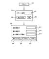
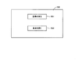
図11は、ユーザに目的を選択させる目的選択画面500を示す図である。ネットワークに接続されるデバイスが多くなると、制御装置のメニュー画面で全てのデバイスのサービスを利用できるようにすると視認性を損なう場合がある。そこで、上位階層のメニュー画面ではUPnPネットワークを用いる目的をユーザに選択させ、下位階層のメニュー画面では上位メニューで選択された目的に応じたデバイスが提供するサービスのみにアクセスできるようにしてもよい。このような目的の設定方法としては、例えば、画像、音楽、文書というようにデータの種類で分類される目的を設定する方法、画像を見る、音楽を聞くというようにユーザの行為で分類される目的を設定する方法、よく使う機能、最近使った機能というように利用頻度で分類される目的を設定する方法等がある。
FIG. 11 is a diagram showing a
以下、図12及び図13に基づいて具体的に説明する。はじめに、制御装置としてのPC1は図13に例示する目的管理テーブルに基づいて目的選択画面500を表示部25に表示する(S200)。目的管理テーブルは、制御プログラムの一部としてHDD22にあらかじめ記憶されている。目的とデバイスのサービスとは、目的管理テーブルとサービス管理テーブルとによって関連付けられている。目的管理テーブルの各レコードは、各目的について、目的選択ボタン501、502のリソースデータにアクセスするための識別子(ラベル、ポインタ等)と、目的選択ボタン501、502の画面上の表示位置と、目的が選択されたときにアクセス対象となるデバイスの種類(デバイスタイプ)とを関連付けている。
Hereinafter, a specific description will be given based on FIGS. 12 and 13. First, the PC 1 as the control device displays a
次に、目的選択ボタン501、502がマウスによるクリック等によって選択されると(S202)、PC1は選択されたボタンに関連付けられたデバイスタイプを特定し(S204)、特定したデバイスタイプに属するデバイスが提供するサービスを検出し(S206)、検出したサービスにアクセスするための制御画面部品を表示する(S208)。具体的には例えば「画像を見る」ボタン501が選択された場合、図1(A)に示す制御画面を表示部に表示する。
Next, when the
尚、同一のデバイスタイプに属する異なるデバイスがネットワーク11に接続されている場合、ある目的が選択された場合に、その目的の達成に最もよく適合するデバイスが提供するサービスにのみアクセスする制御画面を表示するようにしてもよい。具体的には例えば、TVモニタとディジタルピクチャフレームがネットワーク11に接続されている状態で「画像を楽しむ」という目的が選択された場合、画面サイズがより大きい方のデバイスが提供するサービスにのみアクセスする制御画面を表示するようにしてもよい。目的に適合するデバイスの選択は各デバイスのSDDを比較することによって可能になる。 When different devices belonging to the same device type are connected to the network 11, when a certain purpose is selected, a control screen for accessing only a service provided by a device that best suits the achievement of the purpose is displayed. You may make it display. Specifically, for example, when the purpose of “enjoying an image” is selected while a TV monitor and a digital picture frame are connected to the network 11, only the service provided by the device with the larger screen size is accessed. A control screen may be displayed. Selection of a device that fits the purpose is made possible by comparing the SDD of each device.
以上説明した本発明の実施例によると、制御装置としてのPC1が画面表示した制御画面部品をユーザが選択した場合に、選択された制御画面部品にアクション及び状態変数を介して関連付けられているサービスを、PC1の制御下でデバイスに提供させることにより、ユーザは制御装置としての1台のPC1によって種々のデバイスを操作できるようになる。 According to the embodiment of the present invention described above, when the user selects a control screen component displayed on the screen by the PC 1 as the control device, a service associated with the selected control screen component via an action and a state variable. Is provided to the device under the control of the PC 1, the user can operate various devices by one PC 1 as a control device.
また、制御装置としてのPC1は、DCPに応じて予めリソースデータが記憶された制御画面部品をデバイスの接続状態に応じて表示し、デバイスを制御するための情報(制御情報)をデバイスから自律的に取得するため、制御画面部品のリソースデータや制御情報をネットワーク11にデバイスを接続するたびにユーザが制御装置としてのPC1に入力する必要が無くなる。そのため、ネットワークに接続して利用される種々のデバイスの操作が容易になる。 In addition, the PC 1 as the control device autonomously displays control screen components in which resource data is stored in advance according to the DCP according to the connection state of the device, and autonomously transmits information (control information) for controlling the device from the device. Therefore, every time a device is connected to the network 11, it is not necessary for the user to input the resource data and control information of the control screen component to the PC 1 as the control device. Therefore, it becomes easy to operate various devices used by connecting to the network.
また、制御装置としてのPC1が複数のデバイスが提供するサービスに連続してアクセスするための制御画面部品を表示することにより、ユーザはPC1に表示される制御画面を操作することによって複数のデバイスを協働させることができる。その結果、個々のデバイス単独では実現不可能な機能をユーザはPC1を介して容易に利用できるようになる。
尚、上記実施例においては、UPnPネットワークに本発明を適用した例を説明したが、特定の制御装置の制御下で能動的に複数のネットワークデバイスを作動させるプロトコルを用いて構成されたネットワークであれば本発明を適用することができる。
In addition, the PC 1 as the control device displays control screen components for continuously accessing services provided by a plurality of devices, so that the user operates the control screen displayed on the PC 1 to display a plurality of devices. Can work together. As a result, the user can easily use functions that cannot be realized by individual devices alone via the PC 1.
In the above embodiment, an example in which the present invention is applied to a UPnP network has been described. However, the network may be configured using a protocol that actively operates a plurality of network devices under the control of a specific control device. The present invention can be applied.
1 PC(制御装置)、2 ワイヤレスハンドヘルドPC(制御装置)、3 スキャナ(デバイス)、4 プリンタ(デバイス)、5 ファイルサーバ(デバイス)、6 オーディオプレーヤ(デバイス)、7 プロジェクタ(デバイス)、8 ルータ(デバイス)、9 ディジタルカメラ(デバイス)、10 TVモニタ(デバイス)、22 HDD(メモリ)、102、103、104、105、106、107、214、215、216、318、319、320、211、212、213、312、313、314、317、315 制御画面部品 1 PC (control device) 2 Wireless handheld PC (control device) 3 Scanner (device) 4 Printer (device) 5 File server (device) 6 Audio player (device) 7 Projector (device) 8 Router (Device), 9 digital camera (device), 10 TV monitor (device), 22 HDD (memory), 102, 103, 104, 105, 106, 107, 214, 215, 216, 318, 319, 320, 211, 212, 213, 312, 313, 314, 317, 315 Control screen components
Claims (9)
ネットワークに接続されているデバイスが提供するサービスを検出する検出手段と、
検出された前記サービスに関連付けられた前記制御画面部品を選択可能に画面表示する制御画面表示手段と、
画面表示された前記制御画面部品の選択を受け付ける制御選択手段と、
選択された前記制御画面部品に関連付けられた前記サービスを前記デバイスに提供させる制御手段と、
を備えることを特徴とする制御装置。 Memory that stores control screen parts,
Detection means for detecting a service provided by a device connected to the network;
Control screen display means for displaying the control screen component associated with the detected service in a selectable manner;
Control selection means for receiving selection of the control screen component displayed on the screen;
Control means for causing the device to provide the service associated with the selected control screen component;
A control device comprising:
前記検出手段は、前記ネットワークに接続されている前記デバイスから当該デバイスを制御するための制御情報を取得し、
前記制御手段は、取得した前記制御情報に基づいて前記デバイスを制御し、前記デバイスに前記サービスを提供させることを特徴とする請求項1に記載の制御装置。 In the memory, a plurality of the services defined by a device control protocol and a plurality of the control screen components are stored in association with each other,
The detection means acquires control information for controlling the device from the device connected to the network,
The control apparatus according to claim 1, wherein the control unit controls the device based on the acquired control information and causes the device to provide the service.
前記制御手段は、選択された前記制御画面部品に関連付けられた前記機能を実現する複数の前記サービスを前記デバイスに提供させることを特徴とする請求項1に記載の制御装置。 The control screen display means screen-selectively displays the control screen component associated with a function realized by a combination of different services provided by a plurality of the devices,
The control apparatus according to claim 1, wherein the control unit causes the device to provide a plurality of the services that realize the function associated with the selected control screen component.
画面表示された前記目的の選択を受け付ける目的選択手段とをさらに備え、
前記制御画面表示手段は、複数の前記制御画面のうち選択された前記目的に関連付けられた前記制御画面部品を選択可能に画面表示することを特徴とする請求項1又は3に記載の制御装置。 A purpose selection screen display means for displaying a purpose selectable screen;
And a purpose selecting means for receiving selection of the purpose displayed on the screen,
The control apparatus according to claim 1 or 3, wherein the control screen display means displays the control screen component associated with the selected purpose among a plurality of the control screens in a selectable manner.
予め記憶されている制御画面部品のうち、検出された前記サービスに関連付けられた前記制御画面部品を選択可能に画面表示するステップと、
画面表示された前記制御画面部品の選択を受け付けるステップと、
選択された前記制御画面部品に関連付けられた前記サービスを前記デバイスに提供させるステップと、
を含むことを特徴とする制御方法。 Detecting a service provided by a device connected to the network;
A step of screen-selectively displaying the control screen component associated with the detected service among the control screen components stored in advance;
Receiving a selection of the control screen component displayed on the screen;
Causing the device to provide the service associated with the selected control screen component;
The control method characterized by including.
予め記憶されている制御画面部品のうち、検出された前記サービスに関連付けられた前記制御画面部品を選択可能に画面表示する制御画面表示手段と、
画面表示された前記制御画面部品の選択を受け付ける制御選択手段と、
選択された前記制御画面部品に関連付けられた前記サービスを前記デバイスに提供させる制御手段と、
としてコンピュータを機能させる制御プログラム。 Detection means for detecting a service provided by a device connected to the network;
Control screen display means for selectively displaying the control screen component associated with the detected service among control screen components stored in advance;
Control selection means for receiving selection of the control screen component displayed on the screen;
Control means for causing the device to provide the service associated with the selected control screen component;
As a control program that causes the computer to function.
予め記憶されている制御画面部品のうち、検出された前記サービスに関連付けられた前記制御画面部品を選択可能に画面表示する制御画面表示手段と、
画面表示された前記制御画面部品の選択を受け付ける制御選択手段と、
選択された前記制御画面部品に関連付けられた前記サービスを前記デバイスに提供させる制御手段と、
としてコンピュータを機能させる制御プログラムが記録された記録媒体。
Detection means for detecting a service provided by a device connected to the network;
Control screen display means for selectively displaying the control screen component associated with the detected service among control screen components stored in advance;
Control selection means for receiving selection of the control screen component displayed on the screen;
Control means for causing the device to provide the service associated with the selected control screen component;
As a recording medium on which a control program for causing a computer to function is recorded.
Priority Applications (2)
| Application Number | Priority Date | Filing Date | Title |
|---|---|---|---|
| JP2004109052A JP2005293352A (en) | 2004-04-01 | 2004-04-01 | Control device, control method, and control program |
| US11/097,872 US20050232583A1 (en) | 2004-04-01 | 2005-03-31 | Control apparatus, control method, and control program product |
Applications Claiming Priority (1)
| Application Number | Priority Date | Filing Date | Title |
|---|---|---|---|
| JP2004109052A JP2005293352A (en) | 2004-04-01 | 2004-04-01 | Control device, control method, and control program |
Publications (1)
| Publication Number | Publication Date |
|---|---|
| JP2005293352A true JP2005293352A (en) | 2005-10-20 |
Family
ID=35096367
Family Applications (1)
| Application Number | Title | Priority Date | Filing Date |
|---|---|---|---|
| JP2004109052A Pending JP2005293352A (en) | 2004-04-01 | 2004-04-01 | Control device, control method, and control program |
Country Status (2)
| Country | Link |
|---|---|
| US (1) | US20050232583A1 (en) |
| JP (1) | JP2005293352A (en) |
Cited By (4)
| Publication number | Priority date | Publication date | Assignee | Title |
|---|---|---|---|---|
| JP2010108212A (en) * | 2008-10-30 | 2010-05-13 | Kyocera Corp | Content processing system, terminal equipment, and content processing method |
| JP2011141788A (en) * | 2010-01-08 | 2011-07-21 | Onkyo Corp | Device operation responding computer device |
| US8150978B2 (en) | 2005-11-17 | 2012-04-03 | Samsung Electronics Co., Ltd. | Apparatus and method for managing user interface |
| CN103856349A (en) * | 2012-12-07 | 2014-06-11 | 华为技术有限公司 | Version upgrading method for multi-core router and multi-core router |
Families Citing this family (20)
| Publication number | Priority date | Publication date | Assignee | Title |
|---|---|---|---|---|
| DE102004047876A1 (en) * | 2004-10-01 | 2006-04-06 | Degussa Ag | Powder with improved recycling properties, process for its preparation and use of the powder in a process for producing three-dimensional objects |
| WO2007109556A2 (en) * | 2006-03-16 | 2007-09-27 | Exceptional Innovation, Llc | Automation control system having digital logging |
| US8001219B2 (en) * | 2006-03-16 | 2011-08-16 | Exceptional Innovation, Llc | User control interface for convergence and automation system |
| US7496627B2 (en) * | 2006-03-16 | 2009-02-24 | Exceptional Innovation, Llc | Automation control system having digital logging |
| US7587464B2 (en) | 2006-03-16 | 2009-09-08 | Exceptional Innovation, Llc | Device automation using networked device control having a web services for devices stack |
| US7966083B2 (en) | 2006-03-16 | 2011-06-21 | Exceptional Innovation Llc | Automation control system having device scripting |
| US8155142B2 (en) * | 2006-03-16 | 2012-04-10 | Exceptional Innovation Llc | Network based digital access point device |
| US8209398B2 (en) * | 2006-03-16 | 2012-06-26 | Exceptional Innovation Llc | Internet protocol based media streaming solution |
| US8725845B2 (en) * | 2006-03-16 | 2014-05-13 | Exceptional Innovation Llc | Automation control system having a configuration tool |
| US7509402B2 (en) * | 2006-03-16 | 2009-03-24 | Exceptional Innovation, Llc | Automation control system having a configuration tool and two-way ethernet communication for web service messaging, discovery, description, and eventing that is controllable with a touch-screen display |
| WO2007126781A2 (en) | 2006-03-27 | 2007-11-08 | Exceptional Innovation Llc | Set top box for convergence and automation system |
| WO2007124453A2 (en) | 2006-04-20 | 2007-11-01 | Exceptional Innovation Llc | Touch screen for convergence and automation system |
| US7667968B2 (en) | 2006-05-19 | 2010-02-23 | Exceptional Innovation, Llc | Air-cooling system configuration for touch screen |
| KR101264318B1 (en) * | 2006-07-07 | 2013-05-22 | 삼성전자주식회사 | Method for providing service menu and service to network environment and the service providing apparatus thereof |
| US7962130B2 (en) | 2006-11-09 | 2011-06-14 | Exceptional Innovation | Portable device for convergence and automation solution |
| WO2008143881A1 (en) * | 2007-05-14 | 2008-11-27 | Exceptional Innovation, Llc | Customizable media device |
| US8686890B2 (en) | 2007-05-25 | 2014-04-01 | Exceptional Innovation, Llc | Customizable remote control device |
| US8032661B2 (en) * | 2008-02-28 | 2011-10-04 | Microsoft Corporation | Automatic peripheral device sharing |
| US8516071B2 (en) * | 2009-06-03 | 2013-08-20 | Qualcomm Incorporated | Systems and methods for creating virtual universal plug-and-play systems |
| US10331312B2 (en) | 2015-09-08 | 2019-06-25 | Apple Inc. | Intelligent automated assistant in a media environment |
Citations (5)
| Publication number | Priority date | Publication date | Assignee | Title |
|---|---|---|---|---|
| JPH0744474A (en) * | 1993-07-30 | 1995-02-14 | Canon Inc | System control method and device |
| JPH09128181A (en) * | 1995-10-10 | 1997-05-16 | Xerox Corp | Method for retrieval of interface control with reference to user display |
| JP2002300332A (en) * | 2001-03-30 | 2002-10-11 | Minolta Co Ltd | Management device, image processing unit, management method, management program and recording medium |
| JP2002373128A (en) * | 2001-06-13 | 2002-12-26 | Konica Corp | Service system and method for providing service using the same system and its program |
| JP2003345685A (en) * | 2002-05-22 | 2003-12-05 | Seiko Epson Corp | Device sharing system, device management terminal, gateway terminal, device, terminal program, device program, and method for providing device sharing service |
Family Cites Families (6)
| Publication number | Priority date | Publication date | Assignee | Title |
|---|---|---|---|---|
| DE69838439T2 (en) * | 1997-06-25 | 2008-06-12 | Samsung Electronics Co., Ltd., Suwon | Method and device for monitoring devices in a home network |
| IL139410A0 (en) * | 1998-05-07 | 2001-11-25 | Samsung Electronics Co Ltd | Method and apparatus for universally accessible command and control information in a network |
| JP4424711B2 (en) * | 2000-06-30 | 2010-03-03 | キヤノン株式会社 | Network device, directory server and network system |
| US6930730B2 (en) * | 2001-05-03 | 2005-08-16 | Mitsubishi Digital Electronics America, Inc. | Control system and user interface for network of input devices |
| US7337402B2 (en) * | 2001-11-09 | 2008-02-26 | Microsoft Corporation | Tunable information presentation appliance using an extensible markup language |
| US7234115B1 (en) * | 2002-09-26 | 2007-06-19 | Home Director, Inc. | Home entertainment system and method |
-
2004
- 2004-04-01 JP JP2004109052A patent/JP2005293352A/en active Pending
-
2005
- 2005-03-31 US US11/097,872 patent/US20050232583A1/en not_active Abandoned
Patent Citations (5)
| Publication number | Priority date | Publication date | Assignee | Title |
|---|---|---|---|---|
| JPH0744474A (en) * | 1993-07-30 | 1995-02-14 | Canon Inc | System control method and device |
| JPH09128181A (en) * | 1995-10-10 | 1997-05-16 | Xerox Corp | Method for retrieval of interface control with reference to user display |
| JP2002300332A (en) * | 2001-03-30 | 2002-10-11 | Minolta Co Ltd | Management device, image processing unit, management method, management program and recording medium |
| JP2002373128A (en) * | 2001-06-13 | 2002-12-26 | Konica Corp | Service system and method for providing service using the same system and its program |
| JP2003345685A (en) * | 2002-05-22 | 2003-12-05 | Seiko Epson Corp | Device sharing system, device management terminal, gateway terminal, device, terminal program, device program, and method for providing device sharing service |
Cited By (6)
| Publication number | Priority date | Publication date | Assignee | Title |
|---|---|---|---|---|
| US8150978B2 (en) | 2005-11-17 | 2012-04-03 | Samsung Electronics Co., Ltd. | Apparatus and method for managing user interface |
| JP2013041611A (en) * | 2005-11-17 | 2013-02-28 | Samsung Electronics Co Ltd | Device and method for managing and displaying user interface |
| US8521814B2 (en) | 2005-11-17 | 2013-08-27 | Samsung Electronics Co., Ltd. | Apparatus and method for managing user interface |
| JP2010108212A (en) * | 2008-10-30 | 2010-05-13 | Kyocera Corp | Content processing system, terminal equipment, and content processing method |
| JP2011141788A (en) * | 2010-01-08 | 2011-07-21 | Onkyo Corp | Device operation responding computer device |
| CN103856349A (en) * | 2012-12-07 | 2014-06-11 | 华为技术有限公司 | Version upgrading method for multi-core router and multi-core router |
Also Published As
| Publication number | Publication date |
|---|---|
| US20050232583A1 (en) | 2005-10-20 |
Similar Documents
| Publication | Publication Date | Title |
|---|---|---|
| JP2005293352A (en) | Control device, control method, and control program | |
| US7962097B2 (en) | Method and system for identifying device on universal plug and play network and playing content using the device | |
| JP4309087B2 (en) | Network connection device and network system using the same | |
| US20030140343A1 (en) | Remote wireless device with EPG display, intercom and emulated control buttons | |
| JP2005292903A (en) | Control system, control program, control method, and control apparatus | |
| JP4687746B2 (en) | CONFERENCE SYSTEM, DATA PROCESSING DEVICE, IMAGE TRANSMITTING METHOD, AND IMAGE TRANSMITTING PROGRAM | |
| CN102415104A (en) | Remote user interface system and method | |
| JP2009146146A (en) | Information processing apparatus and home network system | |
| JP4540377B2 (en) | UI display device and UI display method | |
| EP2472774A2 (en) | Remote control method and system using control user interface | |
| JP2010055275A (en) | Information processing apparatus and function expansion method | |
| US20120280801A1 (en) | Controlled device, device control system, device control program and device control method | |
| EP1876762B1 (en) | Method for providing a service menu in a network environment | |
| JP4774473B2 (en) | Device registration method and server device | |
| CN101166131B (en) | Universal plug and play based network system and method of controlling the same | |
| JP2010026780A (en) | Information processor, information processing method, and information processing program | |
| US11842518B2 (en) | Camera apparatus, control method for camera apparatus, and storage medium | |
| CN112347275B (en) | Media file push method, device, equipment and computer-readable storage medium | |
| JP2005064755A (en) | Remote control system, remote control device, remote control terminal, controlled device, remote control method and program | |
| JP5797674B2 (en) | Operation assistant terminal, operator server, operation assistant method, and operation assistant program | |
| US9184931B2 (en) | Universal plug and play based network system and method of controlling the same | |
| JP2007318542A (en) | Control device and control method thereof | |
| CN120653336A (en) | Display device, terminal device and file display method | |
| JP2010093420A (en) | Apparatus, method and system for macro management | |
| TW201249197A (en) | Video system and operating method thereof |
Legal Events
| Date | Code | Title | Description |
|---|---|---|---|
| RD04 | Notification of resignation of power of attorney |
Free format text: JAPANESE INTERMEDIATE CODE: A7424 Effective date: 20060818 |
|
| RD04 | Notification of resignation of power of attorney |
Free format text: JAPANESE INTERMEDIATE CODE: A7424 Effective date: 20061222 |
|
| RD03 | Notification of appointment of power of attorney |
Free format text: JAPANESE INTERMEDIATE CODE: A7423 Effective date: 20061226 |
|
| A621 | Written request for application examination |
Free format text: JAPANESE INTERMEDIATE CODE: A621 Effective date: 20070314 |
|
| RD04 | Notification of resignation of power of attorney |
Free format text: JAPANESE INTERMEDIATE CODE: A7424 Effective date: 20070403 |
|
| A977 | Report on retrieval |
Free format text: JAPANESE INTERMEDIATE CODE: A971007 Effective date: 20091201 |
|
| A131 | Notification of reasons for refusal |
Free format text: JAPANESE INTERMEDIATE CODE: A131 Effective date: 20100330 |
|
| A521 | Request for written amendment filed |
Free format text: JAPANESE INTERMEDIATE CODE: A523 Effective date: 20100524 |
|
| A131 | Notification of reasons for refusal |
Free format text: JAPANESE INTERMEDIATE CODE: A131 Effective date: 20110208 |
|
| A521 | Request for written amendment filed |
Free format text: JAPANESE INTERMEDIATE CODE: A523 Effective date: 20110407 |
|
| A02 | Decision of refusal |
Free format text: JAPANESE INTERMEDIATE CODE: A02 Effective date: 20110712 |