JP2005293345A - System and method for diagnosing failure using ic tag - Google Patents
System and method for diagnosing failure using ic tag Download PDFInfo
- Publication number
- JP2005293345A JP2005293345A JP2004108889A JP2004108889A JP2005293345A JP 2005293345 A JP2005293345 A JP 2005293345A JP 2004108889 A JP2004108889 A JP 2004108889A JP 2004108889 A JP2004108889 A JP 2004108889A JP 2005293345 A JP2005293345 A JP 2005293345A
- Authority
- JP
- Japan
- Prior art keywords
- unit
- tag
- failure
- information
- units
- Prior art date
- Legal status (The legal status is an assumption and is not a legal conclusion. Google has not performed a legal analysis and makes no representation as to the accuracy of the status listed.)
- Pending
Links
- 238000000034 method Methods 0.000 title claims abstract description 14
- 238000003745 diagnosis Methods 0.000 claims description 17
- 238000001514 detection method Methods 0.000 claims description 15
- 230000005856 abnormality Effects 0.000 description 102
- 238000012423 maintenance Methods 0.000 description 22
- 230000002159 abnormal effect Effects 0.000 description 5
- 230000006870 function Effects 0.000 description 5
- 238000010586 diagram Methods 0.000 description 2
- 230000005540 biological transmission Effects 0.000 description 1
Images


Landscapes
- Credit Cards Or The Like (AREA)
- Debugging And Monitoring (AREA)
Abstract
Description
本発明は、ICタグを用いた故障診断システムおよび故障診断方法に関するものである。 The present invention relates to a failure diagnosis system and a failure diagnosis method using an IC tag.
プロセッサにより各種業務処理を行う装置に異常が発生した場合、検出した異常が記憶部に書き込まれているので、この異常情報を取り出すために当該装置の保守要員用のパネルを操作して外部媒体に書き出したり、印刷装置に印刷させたりしていた。 When an abnormality occurs in a device that performs various business processes by the processor, the detected abnormality is written in the storage unit.To retrieve this abnormality information, operate the panel for maintenance personnel of the relevant device to the external medium. It was written out or printed on a printing device.
また、大きな計算機システムでは当該計算機システムを構成するユニットに障害発生したときにSVP(サービスプロセッサ)に当該障害を自動収集させて記憶させることが行われている(特許文献1)。
しかし、上述した前者の技術では、異常情報を取り出すのに、保守対象装置の保守要員用のパネルを操作して保守対象装置から異常情報を取り出す必要があり、保守時の操作ミスによりシステムダウンや重大な影響、例えばオンラインシステムで業務を停止させ重大な影響を与えてしまうという問題があった。 However, in the former technique described above, in order to extract the abnormality information, it is necessary to operate the panel for maintenance personnel of the maintenance target device to extract the abnormality information from the maintenance target device. There has been a serious influence, for example, a problem that the business is stopped by the online system and has a serious influence.
また、後者の技術では、SVPという特別の保守専用装置を設ける必要があると共に、SVPと保守対象装置を構成する多数のユニットとの間のデータ送受信路が必要となってしまうと共に、当該データ送受信路に障害発生するとユニットの異常情報を収集できないという問題がある。 In the latter technique, it is necessary to provide a special maintenance dedicated device called SVP, and a data transmission / reception path between the SVP and a large number of units constituting the maintenance target device is required. There is a problem that unit abnormality information cannot be collected if a road failure occurs.
また、異常情報を収集する際に、従来は必ず保守対象装置の電源が入っていることが必要で、電源が落ちて(電源断)であれば、異常情報を収集することができないという問題があった。 In addition, when collecting abnormality information, conventionally, the maintenance target device must always be turned on, and if the power is off (power is cut off), abnormality information cannot be collected. there were.
本発明は、これらの問題を解決するため、装置を構成するユニットあるいは複数のユニットに対応づけてICタグを装着し収集した障害情報を書き込み、ICタグからユニット毎の障害情報を読み出して障害発生したユニットを特定および解析結果を提示するようにしている。 In order to solve these problems, the present invention writes failure information collected by mounting an IC tag in association with a unit or a plurality of units constituting the apparatus, and reads failure information for each unit from the IC tag to generate a failure. The specified unit is identified and the analysis result is presented.
従って、保守対象の装置を操作することなく、また保守対象装置の電源が入っていなくても、独立に保守対象の装置のユニット毎の障害情報を収集して障害発生したユニットを特定、障害解析結果を提示することが可能となる。 Therefore, even if the maintenance target device is not operated and the maintenance target device is not turned on, the failure information for each unit of the maintenance target device is independently collected to identify the failure unit and analyze the failure. The result can be presented.
本願発明は、装置を構成するユニットあるいは複数のユニットに対応づけてICタグを装着し収集した障害情報を書き込み、ICタグからユニット毎の障害情報を読み出して障害発生したユニットを特定および解析結果を提示し、保守対象の装置を操作することなく、または、保守対象装置の電源が入っていなくても、独立に保守対象の装置のユニット毎の障害情報を収集して障害発生したユニットを特定、障害解析結果を提示することができる。 The invention of the present application writes failure information collected by attaching an IC tag in association with a unit or a plurality of units constituting the apparatus, reads failure information for each unit from the IC tag, identifies the unit in which the failure has occurred, and displays the analysis result Presenting and identifying failure units by collecting failure information for each unit of maintenance target devices independently without operating the maintenance target device or even if the maintenance target device is not powered on. Failure analysis results can be presented.
これにより、保守対象の装置に触らなくても(操作しなくても)、ICタグに書き込まれたユニット毎の障害情報を読み出せるので、
(1) 保守対象の装置に全く影響を与えることなく、障害情報をユニット毎に収集できる。
As a result, the failure information for each unit written in the IC tag can be read without touching (not operating) the maintenance target device.
(1) Fault information can be collected for each unit without affecting the maintenance target device.
(2) 保守時に操作ミスによるシステム(装置)ダウンや戻し忘れ(ユニットのテスト状態から運用状態への戻し忘れ)などの作業ミスを完全に防止できる。 (2) It is possible to completely prevent work mistakes such as system (device) down or forgetting to return (forgetting to return from the unit test state to the operating state) due to an operation error during maintenance.
(3) 保守時の障害情報の読み出しを、ユーザのシステム(装置)と全く独立した別経路で行えるので、ユーザのシステム(装置)に診断用のソフトを組み込むことによるトラブルを防止できる。 (3) Since failure information can be read out during maintenance through a separate route that is completely independent of the user's system (device), troubles caused by incorporating diagnostic software into the user's system (device) can be prevented.
(4) ユーザの装置の運用中に、独立した別経路で障害発生したユニットを特定(ICタグからユニット毎の障害情報を読み出して障害発生のユニットを特定)して当該ユニット(部品)の手配ができ、運用終了を待つことなく、障害修復時間の大幅な短縮を図ることができる。 (4) During operation of the user's device, identify the unit that has failed along an independent path (read out the failure information for each unit from the IC tag to identify the unit that has failed) and arrange the unit (part) Therefore, the failure repair time can be greatly shortened without waiting for the end of operation.
本発明は、装置を構成するユニットあるいは複数のユニットに対応づけてICタグを装着し収集した障害情報を書き込み、ICタグからユニット毎の障害情報を読み出して障害発生したユニットを特定および解析結果を提示することを実現した。 The present invention writes the failure information collected by attaching an IC tag in association with a unit or a plurality of units constituting the apparatus, reads the failure information for each unit from the IC tag, identifies the unit in which the failure has occurred, and displays the analysis result Realized to present.
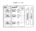
図1は、本発明のシステム構成図を示す。
図1において、処理装置1は、保守対象の装置の例であって、プログラムに従い処理を行う装置であり、ここでは、交換可能なユニット(1)、(2)・・・(6)から構成されるものである。
FIG. 1 shows a system configuration diagram of the present invention.
In FIG. 1, a
ユニット2は、処理装置1を構成する交換可能な部品の単位であって、ここでは、処理部21、異常検出部22、異常情報収集部23、およびICタグ書込部24などから構成されるものである。
The
処理部21は、プログラムまたは回路に従い各種処理を行うものである。
異常検出部22は、ユニット2内の各種異常(例えばセンサにより検出される異常、ソフトやOSにより検出される異常(ソフト動作停止異常、例外処理異常など))を検出するものであって、異常検出回路やセンサや異常検出ソフトなどである。
The
The
異常情報収集部23は、異常検出部22で検出された異常情報を収集(例えば異常発生時刻を付与して異常情報を収集およびそのときのユニットの状態情報を収集)するものである。
The abnormality
ICタグ書込部24は、無線でICタグ3に異常情報を書き込むものである(図3参照)。
The IC
ICタグ3は、無線でデータを書き込んで保存したり、無線でデータを読み出したりする公知のICタグであって、ここでは、ユニット2毎に装着したものである。尚、複数のユニット3毎に1つのICタグ3を装着するようにしてもよい(図5参照)。
The
ICタグ読取部4は,ICタグ23から無線でデータ(ここでは、ユニット2毎の異常情報(障害情報))を読み取るものである。
The IC
端末5は、ICタグ読取部4で読み取ったデータ(ユニット2の障害情報)を解析して障害発生のユニット2を特定、解析結果を表示するものであって、診断解析部51、表示部52などから構成されるものである。
The terminal 5 analyzes the data read by the IC tag reading unit 4 (failure information of the unit 2), identifies the
診断解析部51は、ICタグ3から読み取ったユニット2毎の障害情報を解析し、障害発生したユニット2を特定、および障害解析結果を生成するものである。
The
表示部52は、診断解析部51で解析して特定した障害発生したユニット2および解析結果を表示するものである。
The
次に、図2のフローチャートの順番に従い、図1の構成の動作を詳細に説明する。
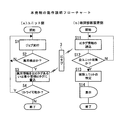
図2は、本発明の動作説明フローチャートを示す。
Next, the operation of the configuration of FIG. 1 will be described in detail according to the order of the flowchart of FIG.
FIG. 2 shows a flowchart for explaining the operation of the present invention.
図2の(a)はユニット2側のフローチャートであり、図2の(b)は故障診断装置(端末5)側のフローチャートである。
2A is a flowchart on the
図2の(a)において、S1は、ジョブ実行する。これは、図1の処理装置1がジョブを実行する。
In FIG. 2A, S1 executes a job. This is because the
S2は、異常検出か判別する。これは、S1のジョブ実行中に、図1の各ユニット2内の異常検出部22、更に、処理装置1の異常検出部が異常を検出(センサによる異常検出、ソフトによる異常検出)か判別する。YESの場合には、S3に進む。NOの場合にはS1以降を繰り返す。
In S2, it is determined whether an abnormality has been detected. This is because whether or not the
S3は、S2のYESで異常検出されたので、異常情報を自ICタグ3あるいは集中管理ICタグ3に書き込む。これは、検出された異常情報(障害情報)を図1のユニット2にそれぞれ装着された自己のICタグ3に書き込む、あるいは後述する図5の(a)の複数のユニット2に対して1つのICタグ3(集中管理ICタグ3)を設けたときは、当該複数のユニット2のICタグ書込部24(異常発生したもの)が異常情報をICタグ3(集中管理ICタグ3)に異常情報を書き込む。
In S3, since abnormality is detected in YES of S2, the abnormality information is written in the
S4は、リトライ可能か判別する。YESの場合には、S1に戻り繰り返す。NOの場合には、終了する。 In S4, it is determined whether a retry is possible. If yes, return to S1 and repeat. If NO, the process ends.
以上によって、ユニット2側で、異常検出されたときに当該異常検出されたユニット2の異常情報をICタグ3に書き込んで記憶させることが可能となる。
As described above, when the abnormality is detected on the
図2の(b)において、S11は、ICタグ情報の読み込みを行う。これは、図1のICタグ読取部4がユニット2毎(図5の(a)の複数のユニット2毎)に装着したICタグ3からユニット2の異常情報(障害情報)を読み込む。
In FIG. 2B, S11 reads the IC tag information. This is because the IC
S12は、全ユニットの異常情報の収集が終了か判別する。YESの場合には、S13に進む。NOの場合には、S11で次のユニット2の異常情報の読み込みを繰り返す。
In S12, it is determined whether or not the collection of the abnormality information for all units is completed. If YES, the process proceeds to S13. In the case of NO, reading of abnormality information of the
S13は、故障ユニットの特定を行う。これは、S11でICタグ3から読み込んだユニット2毎の異常情報をもとに故障ユニットを特定(例えば異常情報のあるユニット2を故障ユニットと特定)する。この際、併せて、異常情報について、故障解析プログラムを起動して解析を実行させ、解析結果を生成する。
In S13, the failure unit is specified. This identifies a failed unit based on the abnormality information for each
S14は、表示する。これは、S13で特定した故障ユニット、故障解析結果を併せて表示する。これを見た保守要員は、いずれのユニットが故障で、故障解析結果を見て、故障の状態を判断することが可能となる。 S14 is displayed. This displays the failure unit specified in S13 and the failure analysis result together. Maintenance personnel who have seen this can determine which unit has a failure and the failure state can be determined by looking at the failure analysis result.
以上のように、処理装置1を構成するユニット2側ではジョブを実行し、ジョブ実行中に異常が検出されたときはその異常情報(およびそのユニットの状態情報)をICタグ3に書き込みで記憶する。一方、保守要員は、図1のICタグ読取部4を装着した端末5を操作し、処理装置1のユニット2に装着したICタグ3から自動的にユニット2毎の異常情報を収集して解析プログラムによって故障ユニットと、更に、故障解析結果を併せてディスプレイに表示させ、当該表示を見て即座に、いずれのユニットに故障発生し、どのような故障かの故障解析結果を見て、部品などの手配を迅速に行うことが可能となる。この際、保守要員は、保守対象の処理装置1の操作パネルを操作することなく、完全に独立にICタグ3からユニット2毎の異常情報を自動的に読み取って解析し、故障ユニットとその故障解析結果を対応づけて表示させ、故障に対処することが可能となる。
As described above, a job is executed on the
図3は、本発明のICタグのデータ構造例を示す。これは、既述した図2のS3でICタグ3に書き込むデータの例であって、ここでは、図示の下記の情報を図1のICタグ書込部24がICタグ3に無線で書き込む。
FIG. 3 shows an example of the data structure of the IC tag of the present invention. This is an example of data to be written to the
・タグID:
・ユニット名:
・仕様:
・版数:
・異常情報:
・退避済フラグ:
・その他:
ここで、タグIDはICタグ3に付与された一意のID(読み書きするときのID)である。ユニット名は異常情報の発生したユニット名である。仕様、版数はユニットの仕様、版数である。異常情報はユニットに発生した異常情報(例えば、記憶装置やバスなどのパリティエラー、各種センサによる異常鑑別センサ信号、リトライエラー(リトライ回数閾値オーバー)、異常発生した時間情報など)である。退避済フラグは図1のICタグ読取部4で読み取って異常情報を退避完了したときにセットするフラグである。
・ Tag ID:
・ Unit name:
·specification:
・ Version number:
・ Abnormal information:
-Saved flag:
・ Other:
Here, the tag ID is a unique ID assigned to the IC tag 3 (ID when reading and writing). The unit name is the name of the unit in which the abnormality information has occurred. Specifications and version numbers are unit specifications and version numbers. The abnormality information is abnormality information generated in the unit (for example, a parity error of a storage device or a bus, an abnormality discrimination sensor signal by various sensors, a retry error (retry count threshold exceeded), time information of occurrence of abnormality). The saved flag is a flag that is set when the abnormal information has been saved by reading with the IC
以上のように、図1のユニット2のICタグ書込部24が無線でユニットに対応づけて異常情報などをICタグ3に書き込んで記憶させ、ユニット2と別の完全に独立したICタグ読取部4が無線でICタグ3からユニット毎の異常情報などを読み取って解析し、故障ユニット2、障害解析結果を提示させることが可能となる。
As described above, the IC
図4は、本発明のICタグ書込フローチャートを示す。これは、既述した図2のS3でユニット2毎の異常情報を無線でICタグ3に書き込むときの詳細フローチャートである。
FIG. 4 shows an IC tag writing flowchart of the present invention. This is a detailed flowchart when the abnormality information for each
図4の(a)において、S21は、ICタグ3に空き領域があるか判別する。YESの場合にはICタグ3に空き領域があると判明したので、S22でユニット2毎の異常情報をICタグ3の空き領域に書き込む。一方、NOの場合には、ICタグ3に空き領域が無いと判明したので、S23で異常情報を一番古いレコードに書き込む(上書きする)。
In FIG. 4A, S21 determines whether the
以上によって、図1のICタグ書込部24がICタグ3にユニット毎の異常情報を書き込む際に、ICタグ3に空きレコードがあればその空きのレコードに異常情報を書込み、一方、空きのレコードがないときは一番古い時間(図3のICタグ3の異常情報中の時間情報、あるいは図示外の実際にICタグ3に異常情報を書き込んだ時間のうちの一番古い時間)のレコードに上書きし、常に最新のユニット毎の異常情報を所定数残すことが可能となる。
As described above, when the IC
図4の(b)において、S31は、同じ異常情報のレコードが有りか判別する。これは、図1のICタグ書込部24がICタグ3にユニット2毎の異常情報を書き込む際に、ICタグ3から同じレコード(ユニット2毎の異常情報が同一のレコード)があるか判別する。YESの場合には、ICタグ3に同一の異常情報が既に書き込まれていたと判明したので、S32で該レコードの回数を+1する(例えば異常情報欄の回数を+1し、当該回数分、発生した旨を記憶する)。一方、NOの場合には、既述した図4の(a)のS21に進み、空き領域(あるいは一番古いレコード)に書き込む。
In FIG. 4B, S31 determines whether there is a record of the same abnormality information. When the IC
以上によって、異常情報をICタグ3に書き込む際に、同一のユニット2毎の異常情報が既にICタグ3に書き込まれていた場合にはそのレコードの回数を+1して発生回数を記憶させ、同一ユニットの異常情報でICタグ3の異常情報が上書きされてしまう事態を無くすことが可能となる。
As described above, when the abnormality information is written in the
図4の(c)において、S41は、ICタグに空き領域があるか判別する。YESの場合には、ICタグに空き領域があると判明したので、既述した図4の(a)のS22で異常情報を空き領域に書き込む。一方、NOの場合には、ICタグ3に空き領域がないと判明したので、別メモリに書き込む(例えば古い時間から所定数のレコードの異常情報を別メモリ(例えば退避用のハードディスク装置)に書込み退避すると共に、現在の異常情報をICタグ3に書き込む)。
In FIG. 4C, S41 determines whether there is a free area in the IC tag. In the case of YES, since it has been found that there is a free area in the IC tag, the abnormality information is written in the free area in S22 of FIG. On the other hand, in the case of NO, since it has been found that there is no free space in the
S42は、ICタグの領域を使用可にする。これは、S41で別メモリ(予備のICタグ3あるいはハードディスク装置)に書き込んで退避したICタグ3の領域(レコード)を使用可(例えば空き)にセットする。ここで、予備のICタグ3は、複数のICタグ3があるときは各ICタグ3に対応づけて予備のICタグ3を設けてそれぞれ退避するようにしてもよいし、また、共用の予備のICタグ3を設けて各ICタグ3が一杯になったときに当該共用の予備のICタグ3に退避するようにしてもよい。
In S42, the area of the IC tag is made usable. In S41, the area (record) of the
図5は、本発明のユニット/ICタグ例を示す。
図5の(a)は、処理装置1が複数のユニット2、ここでは6つのユニット2から構成されている場合に、当該複数のユニット2に対応づけて1つのICタグ3を装着した例を示す。この場合には、各ユニット2は、ICタグ3にユニットIDに対応づけて異常情報を書き込む。
FIG. 5 shows an example of the unit / IC tag of the present invention.
FIG. 5A shows an example in which one
以上のように、複数のユニット2に対応づけて1つのICタグ3を装着し、各ユニット2のIC書込部24がそれぞれユニットIDに対応づけて異常情報をそれぞれ書き込むことにより、複数の交換可能なユニット2に1つのICタグ3で間に合わせ、交換可能なユニット2の数が非常に多くなったときに当該ユニットをグループ分けして当該グループ内の複数ユニット2に1つのICタグ3を装着させることで全てのユニット2の異常情報を収集して当該IDタグ3に書き込ませることが可能となる。
As described above, one
図5の(b)は、複数ユニットに共通の異常情報収集部23、ICタグ書込部24を設けて当該異常情報収集部23、ICタグ書込部24の数を削減した例を示す。ここで、交換可能な各ユニット2は、それぞれ処理部21、異常検出部22を持つ。各ユニット2内の異常検出部22から、全ユニット2で共通の異常情報収集部23が一括して異常情報を収集し、更に、全ユニット2で共通のICタグ書込部24がユニット2毎の異常情報をICタグ3にそれぞれ書き込むようにしている。
FIG. 5B shows an example in which the abnormality
以上の構成により、処理装置1内に交換可能なユニット2が多数ある場合に、異常情報収集部23、ICタグ書込部24を共通にして数を削減し、ユニット2毎の異常情報をICタグ3にそれぞれ書き込むことが可能となる。
With the above configuration, when there are a large number of
図6は、本発明のユニット例を示す。処理装置1を構成するユニット2は、図示のように、処理部21、異常検出部22、異常情報収集部23、ICタグ書込部24などから構成されるものである。
FIG. 6 shows an example unit of the present invention. As shown in the figure, the
処理部21は、機能1処理回路、機能2処理回路・・・機能n処理回路というように、機能1,2・・・n毎に処理を行う回路(あるいは回路とソフトウェア)を持つものである。
The
異常検出部22は、機能1処理回路、機能2処理回路・・・機能n処理回路に対応づけてそれぞれチェック回路1、チェック回路2・・・チェック回路nを設けてそれぞれの異常を検出し、FF(フリップフロップ回路)でその異常をそれぞれ保持し、OR回路でいずれかのチェック回路で異常検出されたときに、異常検出の旨の信号を異常情報収集部23に通知するものである。
The
異常情報収集部23は、異常検出の旨の信号の通知を受けると、異常検出部22を構成するチェック回路1、チェック回路2・・・チェック回路nからのそれぞれの信号を読み取っていずれのものに異常検出されたかを判別し、異常情報を生成するものである。この異常検出時には、ユニット2の状態情報(例えばチェック回路1で異常、チェック回路2で正常などの状態情報)も併せて生成し、異常情報に含ませる。
When the abnormality
ICタグ書込部24は、異常情報収集部23で収集したユニット2毎の異常情報をICタグ3に書き込むものである。
The IC
本発明は、装置を構成するユニットあるいは複数のユニットに対応づけてICタグを装着し収集した障害情報を書き込み、ICタグからユニット毎の障害情報を読み出して障害発生したユニットを特定および解析結果を提示し、保守対象の装置を操作することなく、独立に保守対象の装置のユニット毎の障害情報を収集して障害発生したユニットを特定、障害解析結果を提示することが可能となる。 The present invention writes the failure information collected by attaching an IC tag in association with a unit or a plurality of units constituting the apparatus, reads the failure information for each unit from the IC tag, identifies the unit in which the failure has occurred, and displays the analysis result It is possible to independently collect the failure information for each unit of the maintenance target device, identify the unit in which the failure has occurred, and present the failure analysis result without operating the maintenance target device.
1:処理装置
2:ユニット
21:処理部
22:異常検出部
23:異常情報収集部
24:ICタグ書込部
3:ICタグ
4:ICタグ読取部
5:端末
51:診断解析部
52:表示部
1: processing device 2: unit 21: processing unit 22: abnormality detection unit 23: abnormality information collection unit 24: IC tag writing unit 3: IC tag 4: IC tag reading unit 5: terminal 51: diagnosis analysis unit 52: display Part
Claims (8)
装置を構成するユニットあるいは複数のユニットに対応づけて装着したICタグと、
前記ICタグに、前記ユニットあるいは複数のユニットから収集した障害情報を書き込む書込部とを備え、
前記ICタグからユニットあるいは複数のユニットの障害情報を読み出し得るように構成したことを特徴とするICタグを用いた故障診断システム。 In a fault diagnosis system for diagnosing faults in units constituting a device,
An IC tag mounted in association with a unit constituting a device or a plurality of units;
A writing unit for writing failure information collected from the unit or a plurality of units to the IC tag,
A failure diagnosis system using an IC tag, wherein the failure information of a unit or a plurality of units can be read from the IC tag.
前記読取部で読み取った障害情報から、障害発生したユニットを特定する解析部と
を備えたことを特徴とするICタグを用いた故障診断システム。 A reading unit that is mounted in association with a unit or a plurality of units constituting the apparatus and reads failure information from an IC tag in which failure information of the unit is written;
A failure diagnosis system using an IC tag, comprising: an analysis unit that identifies a unit in which a failure has occurred from failure information read by the reading unit.
を備えたことを特徴とする請求項5記載のICタグを用いた故障診断システム。 The failure diagnosis system using an IC tag according to claim 5, further comprising: an analysis unit that analyzes the failure information read by the reading unit, identifies a unit in which a failure has occurred, and presents a diagnosis result.
装置を構成するユニットあるいは複数のユニットに対応づけて装着したICタグに、前記ユニットあるいは複数のユニットから収集した障害情報を書き込むステップを有し、
前記ICタグからユニットあるいは複数のユニットの障害情報を読み出し得るように構成したことを特徴とするICタグを用いた故障診断方法 In a failure diagnosis method for diagnosing a failure of units constituting a device,
Writing fault information collected from the unit or the plurality of units into an IC tag attached to the unit constituting the apparatus or a plurality of units;
A failure diagnosis method using an IC tag, wherein the failure information of a unit or a plurality of units can be read from the IC tag
前記ステップで読み取った障害情報から、障害発生したユニットを特定するステップと
を有するICタグを用いた故障診断方法。 A step of reading the failure information from the IC tag in which the failure information of the unit is written in correspondence with the unit constituting the device or a plurality of units;
A failure diagnosis method using an IC tag, comprising: identifying a unit in which a failure has occurred from the failure information read in the step.
Priority Applications (1)
| Application Number | Priority Date | Filing Date | Title |
|---|---|---|---|
| JP2004108889A JP2005293345A (en) | 2004-04-01 | 2004-04-01 | System and method for diagnosing failure using ic tag |
Applications Claiming Priority (1)
| Application Number | Priority Date | Filing Date | Title |
|---|---|---|---|
| JP2004108889A JP2005293345A (en) | 2004-04-01 | 2004-04-01 | System and method for diagnosing failure using ic tag |
Publications (1)
| Publication Number | Publication Date |
|---|---|
| JP2005293345A true JP2005293345A (en) | 2005-10-20 |
Family
ID=35326194
Family Applications (1)
| Application Number | Title | Priority Date | Filing Date |
|---|---|---|---|
| JP2004108889A Pending JP2005293345A (en) | 2004-04-01 | 2004-04-01 | System and method for diagnosing failure using ic tag |
Country Status (1)
| Country | Link |
|---|---|
| JP (1) | JP2005293345A (en) |
Cited By (7)
| Publication number | Priority date | Publication date | Assignee | Title |
|---|---|---|---|---|
| JP2007136085A (en) * | 2005-11-22 | 2007-06-07 | Glory Ltd | Special prize buying system, special prize buying apparatus, special prize put-out apparatus, and special prize inspection apparatus |
| WO2007088606A1 (en) * | 2006-02-01 | 2007-08-09 | Fujitsu Limited | Failure information management method, detection method and apparatus, and storage medium |
| JP2007257284A (en) * | 2006-03-23 | 2007-10-04 | Asahi Kasei Homes Kk | Living energy reduction support system |
| JP2007264815A (en) * | 2006-03-27 | 2007-10-11 | Fujitsu Ltd | Maintenance information providing system, maintenance information providing method, and maintenance information providing program |
| JP2009277157A (en) * | 2008-05-16 | 2009-11-26 | Nec Computertechno Ltd | Post code display system, post code display method, and post code display program |
| JP2012155508A (en) * | 2011-01-26 | 2012-08-16 | Nec Corp | Rack mount system for electronic equipment and method for monitoring electronic equipment and rack mount type electronic equipment |
| JP2013182401A (en) * | 2012-03-01 | 2013-09-12 | Nec Computertechno Ltd | Information processor and information output method |
-
2004
- 2004-04-01 JP JP2004108889A patent/JP2005293345A/en active Pending
Cited By (7)
| Publication number | Priority date | Publication date | Assignee | Title |
|---|---|---|---|---|
| JP2007136085A (en) * | 2005-11-22 | 2007-06-07 | Glory Ltd | Special prize buying system, special prize buying apparatus, special prize put-out apparatus, and special prize inspection apparatus |
| WO2007088606A1 (en) * | 2006-02-01 | 2007-08-09 | Fujitsu Limited | Failure information management method, detection method and apparatus, and storage medium |
| JP2007257284A (en) * | 2006-03-23 | 2007-10-04 | Asahi Kasei Homes Kk | Living energy reduction support system |
| JP2007264815A (en) * | 2006-03-27 | 2007-10-11 | Fujitsu Ltd | Maintenance information providing system, maintenance information providing method, and maintenance information providing program |
| JP2009277157A (en) * | 2008-05-16 | 2009-11-26 | Nec Computertechno Ltd | Post code display system, post code display method, and post code display program |
| JP2012155508A (en) * | 2011-01-26 | 2012-08-16 | Nec Corp | Rack mount system for electronic equipment and method for monitoring electronic equipment and rack mount type electronic equipment |
| JP2013182401A (en) * | 2012-03-01 | 2013-09-12 | Nec Computertechno Ltd | Information processor and information output method |
Similar Documents
| Publication | Publication Date | Title |
|---|---|---|
| US6829729B2 (en) | Method and system for fault isolation methodology for I/O unrecoverable, uncorrectable error | |
| JP4717079B2 (en) | Method and system for fault diagnosis and maintenance in computer systems (history-based prioritization of suspicious components) | |
| WO2006110140A1 (en) | System and method of reporting error codes in an electronically controlled device | |
| US6845469B2 (en) | Method for managing an uncorrectable, unrecoverable data error (UE) as the UE passes through a plurality of devices in a central electronics complex | |
| US20100157766A1 (en) | Predicting cartridge failure from cartridge memory data | |
| CN113961478A (en) | Memory fault recording method and device | |
| JP4648961B2 (en) | Apparatus maintenance system, method, and information processing apparatus | |
| JP4479959B2 (en) | Diagnostic system and diagnostic method | |
| JP2005293345A (en) | System and method for diagnosing failure using ic tag | |
| JP4371720B2 (en) | Storage device system and storage system maintenance method | |
| JP4356634B2 (en) | Fault diagnosis circuit, information processing apparatus including the fault diagnosis circuit, fault diagnosis system, and fault diagnosis program | |
| WO2007088606A1 (en) | Failure information management method, detection method and apparatus, and storage medium | |
| CN100449495C (en) | System and method for assisting CPU to drive chip | |
| JP2008198055A (en) | Disk array failure processing system, device, method, and program | |
| US7457990B2 (en) | Information processing apparatus and information processing recovery method | |
| JP2000347892A (en) | Fault indication device on which maintenance component replacement history is reflected | |
| JP2010113463A (en) | Diagnostic system | |
| WO2007099578A1 (en) | Failure analyzer | |
| CN114721850A (en) | Magnetic disk health check method, device, electronic equipment, medium and product | |
| JPH07311697A (en) | Failure display method of computer system | |
| JP2005250577A (en) | Computer system and arithmetic processing module soundness determination method | |
| CN117407207B (en) | Memory fault processing method and device, electronic equipment and storage medium | |
| KR100862407B1 (en) | System and method to detect errors and predict potential failures | |
| JPH11120154A (en) | Access control device and method in computer system | |
| JPH05324367A (en) | Failure information recording method |