JP2005293301A - Workflow analysis report creation system and method, and information processing apparatus - Google Patents
Workflow analysis report creation system and method, and information processing apparatus Download PDFInfo
- Publication number
- JP2005293301A JP2005293301A JP2004108288A JP2004108288A JP2005293301A JP 2005293301 A JP2005293301 A JP 2005293301A JP 2004108288 A JP2004108288 A JP 2004108288A JP 2004108288 A JP2004108288 A JP 2004108288A JP 2005293301 A JP2005293301 A JP 2005293301A
- Authority
- JP
- Japan
- Prior art keywords
- information
- workflow
- analysis report
- analysis
- report creation
- Prior art date
- Legal status (The legal status is an assumption and is not a legal conclusion. Google has not performed a legal analysis and makes no representation as to the accuracy of the status listed.)
- Granted
Links
Images
Landscapes
- Management, Administration, Business Operations System, And Electronic Commerce (AREA)
- Medical Treatment And Welfare Office Work (AREA)
Abstract
【課題】顧客サイトの部門に置かれる装置のパフォーマンスに加え、対象者の動きも分析し、顧客サイトの装置を用いた部門の生産性を評価する。
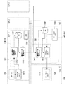
【解決手段】病院サイトHCF1〜nに置かれたモダリティ10に接続されるサービスプロセッサ(SP)30と、SP30に接続されるサービスセンターSVCのデータサーバ44と、医療スタッフ及び患者等のヒトOBの動きに関する情報を検出するヒト追跡センサ20とを備える。SP30は、モダリティ10のパフォーマンス情報に加え、センサ20の検出データを収集してDB32に所定期間保存し、データサーバ44に転送する処理部31を有する。データサーバ44は、SP30からのデータをDBに保存し、保存データに基づき、ヒトOBの動きに関連付けてモダリティ10を用いた検査に関するワークフローを分析してワークフロー分析レポートを作成する処理部41を有する。
【選択図】 図1In addition to the performance of a device placed in a department at a customer site, the movement of a target person is analyzed to evaluate the productivity of the department using the device at the customer site.
A service processor (SP) 30 connected to a modality 10 placed at a hospital site HCF 1 to n, a data server 44 of a service center SVC connected to the SP 30, and human OBs such as medical staff and patients. And a human tracking sensor 20 for detecting information related to movement. The SP 30 includes a processing unit 31 that collects the detection data of the sensor 20 in addition to the performance information of the modality 10, stores it in the DB 32 for a predetermined period, and transfers it to the data server 44. The data server 44 includes a processing unit 41 that stores data from the SP 30 in a DB, analyzes a workflow related to an examination using the modality 10 in association with the movement of a human OB, and creates a workflow analysis report based on the stored data. .
[Selection] Figure 1
Description
本発明は、ワークフロー分析レポートを作成するシステム及びその方法、並びに、情報処理装置に関し、とくに顧客が所有している画像診断機器等の装置の稼動状況や利用状況を提供するサービスにおいて、Web等の技術を使って、顧客向けに表示・提供するサービス方法に関する。 The present invention relates to a system and method for creating a workflow analysis report, and an information processing apparatus. In particular, in a service that provides operating status and usage status of an apparatus such as an image diagnostic device owned by a customer, The present invention relates to a service method for displaying and providing to customers using technology.
近年、病院経営を取り巻く環境は益々厳しくなってきている。特に、画像診断機器を導入し画像情報と診断レポート情報を提供する放射線部門では、画像診断機器の稼動状況や利用状況などの装置パフォーマンス情報を分析し、放射線部門経営の効率化に向けて画像診断機器や人的資源(ヒューマンリソース)を有効に利用することが経営上重要な課題である。これに関連したサービスとして、最近では、装置稼動状況・利用状況に関するサービスや、病院情報システム等における、いくつかのサービスが知られている。 In recent years, the environment surrounding hospital management has become increasingly severe. In particular, in the radiology department that introduces diagnostic imaging equipment and provides image information and diagnostic report information, device performance information such as the operating status and usage status of diagnostic imaging equipment is analyzed to improve the efficiency of the radiation department management. Effective use of equipment and human resources (human resources) is an important management issue. Recently, as services related to this, there are known several services such as a service relating to an apparatus operating status / usage status and a hospital information system.
また、装置パフォーマンス情報のみならず、装置を取り巻く環境(人、モノ、情報等)を含めた稼動状況の情報も、重要なパフォーマンス情報として注目されている。 In addition to apparatus performance information, not only apparatus performance information but also operating status information including the environment (people, things, information, etc.) surrounding the apparatus has attracted attention as important performance information.
例えば、患者単位当たりの検査時間やレポート作成時間のスループット時間や検査技師毎の検査時間など、多種多様なパフォーマンス情報が存在する。これらのパフォーマンス情報を正しく分析し、次の経営アクションへ繋げることが部門経営上必要視されている。 For example, there is a wide variety of performance information such as examination time per patient, throughput time of report creation time, examination time for each laboratory technician, and the like. It is considered necessary for the divisional management to analyze these performance information correctly and connect it to the next management action.
また、装置やその周辺を取り巻く実態に関するパフォーマンスを表す指標項目(メトリックス)には、多種多様なものがあるが、それらのメトリックスを正しく分析するには、人、時間、場所などの分析視点(ビューポイント)が重要とされている。 In addition, there are a wide variety of index items (metrics) that represent performance related to the actual situation surrounding the device and its surroundings. To correctly analyze these metrics, analysis viewpoints (views) of people, time, places, etc. Point) is important.
従来、このような画像診断機器等の装置稼動状況・利用状況に関するサービスとして、顧客向けに部門内のパフォーマンスを分析したカスタマー向け定期レポート(パフォーマンスレポート)を作成する方法及びシステムが知られている。このカスタマー向けレポート作成方法及びシステムの従来例を図9に示す。 2. Description of the Related Art Conventionally, a method and system for creating a periodic report (performance report) for a customer that analyzes the performance in a department for the customer is known as a service related to the operating status and usage status of such an image diagnostic device. FIG. 9 shows a conventional example of the customer report generating method and system.
図9に示すシステムは、各病院サイトHCF1〜n側に設置され且つ病院経営者等の顧客が所有・運用するモダリティ110に接続されるサービスプロセッサ(SP)130と、各病院サイトHCF1〜nに通信回線を介して接続されるサービスセンターSVC側に設置されるデータサーバ(DAS)140と、データサーバ140に通信回線を介して接続される顧客用のパーソナルコンピュータ(ユーザPC)50とを有する。
The system shown in FIG. 9 includes a service processor (SP) 130 installed on each hospital site HCF1-n and connected to a
これにより、モダリティ110から出力される操作情報がサービスプロセッサ130の処理部131の動作にて収集・加工・分析され(情報収集ステップ1311)、1日毎にデータベース(DB)132内に蓄積され(一定期間の情報蓄積ステップ1312)、その蓄積データが、タイマ133の動作ONのタイミングで、サービスセンターSVCへ転送され(蓄積データ転送ステップ1313)、これによりデータサーバ140の処理部141の動作にてデータベース(DB)142に装置毎に引き出せるようデータ格納される(蓄積データ保存ステップ1411)。その後、タイマ143のレポート送信のタイミングで、データベース(DB)142内に貯め込んだ情報が抽出され(情報抽出ステップ1412)、この抽出情報からパフォーマンスレポートが所定フォーマットに合わせて作成され、顧客のユーザPC150にメール送信される。このパフォーマンスレポートは、ユーザPC150の処理部151にて、Web上でも表示される(レポート表示ステップ1511)。
As a result, the operation information output from the
なお、本発明に関連する背景技術としては、以下のものがある。
従来例のカスタマー向けレポート作成方法及びシステムでは、システムや装置の操作に伴うパフォーマンスレポートの作成を行うものであり、システムや装置に関わる医療スタッフや患者等の人の動きも含めたパフォーマンスレポートの作成・分析については意図しておらず、それらの情報を用いた他病院サイトとのベンチマークも困難であり、また実際の値をシミュレーションソフトへ入力する手段もなく、分析に手間がかかるといった課題があった。よって、カスタマー向けレポートでは、モダリティやシステムのパフォーマンスだけではなく、人の動きも分析して、部門の生産性を総合的に評価することが望まれていた。 In the conventional customer report creation method and system, a performance report is created in accordance with the operation of the system and equipment, and a performance report is also created that includes the movement of medical staff and patients related to the system and equipment.・ Analysis is not intended, benchmarking with other hospital sites using that information is difficult, and there is no means to input actual values to simulation software, which requires time and effort. It was. Therefore, it is desired that the report for customers should comprehensively evaluate the productivity of the department by analyzing not only the modality and system performance but also the movement of people.
本発明は、このような従来の事情を背景になされたもので、顧客サイトの部門等に置かれる装置又はシステムのパフォーマンスに加え、対象者の動きも分析し、顧客サイトの装置又はシステムを用いた部門等の生産性を評価することを目的とする。 The present invention has been made against the background of such a conventional situation. In addition to the performance of a device or system placed in a department of a customer site, etc., the movement of a target person is analyzed, and the device or system of the customer site is used. The purpose is to evaluate the productivity of the departments.
上記目的を達成するため、本発明に係る情報処理装置は、遠隔地の医用施設内にある医用装置の動作に関するパフォーマンス情報をネットワークを介して収集し、前記パフォーマンス情報を分析し、その分析結果のレポートを提供する情報処理装置であって、前記医用施設内のセンサにより検出された人の動きに関する情報及び前記パフォーマンス情報を受信する手段と、前記人の動きに関する情報及び前記パフォーマンス情報を保存するデータベース手段と、前記データベースに記憶された前記人の動きに関する情報及び前記パフォーマンス情報に基づき、前記医用施設における作業の分析レポートを作成する処理手段とを有することを特徴とする。 In order to achieve the above object, an information processing apparatus according to the present invention collects performance information regarding the operation of a medical device in a remote medical facility via a network, analyzes the performance information, and analyzes the analysis result. An information processing apparatus that provides a report, and means for receiving information related to human movement and performance information detected by a sensor in the medical facility, and a database for storing information related to human movement and the performance information And processing means for creating an analysis report of work in the medical facility based on the information on the movement of the person stored in the database and the performance information.
また、本発明に係るワークフロー分析レポート作成方法は、顧客サイトに置かれた装置からその装置の動作に関するパフォーマンス情報を収集するステップと、収集された前記パフォーマンス情報を分析して前記装置を用いた作業に関する顧客向けワークフロー分析レポートを作成するステップとを有するワークフロー分析レポート作成方法であって、前記装置を用いた作業を行う作業者を含む対象者の動きに関する情報を検出するステップをさらに備え、前記パフォーマンス情報を収集するステップは、前記パフォーマンス情報に加え、センサの検出データを収集するステップと、収集された前記データを前記情報処理装置に転送するステップとを有し、前記ワークフロー分析レポートを作成するステップは、前記サービスプロセッサからのデータを保存するステップと、保存された前記データに基づき、前記対象者の動きに関連付けて前記装置を用いた作業に関するワークフローを分析し、該分析情報から前記ワークフロー分析レポートを作成するステップとを有することを特徴とする。 The workflow analysis report creation method according to the present invention includes a step of collecting performance information relating to operation of a device from a device placed at a customer site, and a work using the device by analyzing the collected performance information. Creating a workflow analysis report for a customer regarding a workflow analysis report creation method, further comprising the step of detecting information relating to a movement of a target person including a worker who performs work using the apparatus, The step of collecting information includes the step of collecting sensor detection data in addition to the performance information, and the step of transferring the collected data to the information processing apparatus, and creating the workflow analysis report From the service processor Storing data, and analyzing a workflow related to work using the device in association with the movement of the subject based on the stored data, and creating the workflow analysis report from the analysis information It is characterized by that.
本発明に係るワークフロー分析レポート作成方法において、前記分析情報もしくは前記サービスプロセッサで収集された情報を入力してシミュレーション分析を行うステップをさらに備えてもよい。また、自顧客サイトで得られた分析情報に加え、複数の他顧客サイトで得られた分析情報をレポート表示するステップをさらに備えてもよい。 The workflow analysis report creation method according to the present invention may further include a step of performing simulation analysis by inputting the analysis information or the information collected by the service processor. In addition to the analysis information obtained at the own customer site, a step of displaying a report of analysis information obtained at a plurality of other customer sites may be further provided.
さらに、本発明に係るワークフロー分析レポート作成方法において、前記顧客サイトは、病院を含む医療機関であり、前記装置は、前記医療機関の検査室に置かれるモダリティであり、前記対象者は、前記モダリティを用いた検査を医療スタッフ及び該検査の被検者を含み、前記ワークフローは、前記モダリティを用いた検査に関するものであることが好ましい。 Further, in the workflow analysis report creation method according to the present invention, the customer site is a medical institution including a hospital, the device is a modality placed in a laboratory of the medical institution, and the subject is the modality. It is preferable that a test using a medical staff and a subject of the test is included, and the workflow relates to a test using the modality.
本発明に係るワークフロー分析レポート作成システムは、顧客サイトに置かれた装置からその装置の動作に関するパフォーマンス情報を収集するサービスプロセッサと、前記サービスプロセッサからのパフォーマンス情報を分析して前記装置を用いた作業に関する顧客向けワークフロー分析レポートを作成する情報処理装置とを有するワークフロー分析レポート作成システムであって、前記装置を用いた作業を行う作業者を含む対象者の動きに関する情報を検出するセンサをさらに備え、前記サービスプロセッサは、前記パフォーマンス情報に加え、前記センサの検出データを収集する手段と、収集された前記データを前記情報処理装置に転送する通信手段とを有し、前記情報処理装置は、前記サービスプロセッサからのデータを保存するデータベース手段と、保存された前記データに基づき、前記対象者の動きに関連付けて前記装置を用いた作業に関するワークフローを分析し、該分析情報から前記ワークフロー分析レポートを作成する処理手段とを有することを特徴とする。 A workflow analysis report creation system according to the present invention includes a service processor that collects performance information about the operation of a device from a device placed at a customer site, and an operation that uses the device by analyzing performance information from the service processor. A workflow analysis report creation system having an information processing device for creating a workflow analysis report for a customer related to, further comprising a sensor for detecting information on the movement of a target person including a worker who performs work using the device, The service processor includes means for collecting detection data of the sensor in addition to the performance information, and communication means for transferring the collected data to the information processing apparatus. Data that stores data from the processor Based on the stored data, and processing means for analyzing a workflow relating to work using the apparatus in association with the movement of the target person and creating the workflow analysis report from the analysis information. Features.
本発明に係るワークフロー分析レポート作成システムにおいて、前記分析情報もしくは前記サービスプロセッサで収集された情報を入力してシミュレーション分析を行う手段をさらに備えてもよい。また、自顧客サイトで得られた分析情報に加え、複数の他顧客サイトで得られた分析情報をレポート表示する手段をさらに備えてもよい。 The workflow analysis report creation system according to the present invention may further include means for performing simulation analysis by inputting the analysis information or the information collected by the service processor. Further, in addition to the analysis information obtained at the customer site, a means for reporting the analysis information obtained at a plurality of other customer sites may be further provided.
さらに、本発明に係るワークフロー分析レポート作成方法において、前記顧客サイトは、病院を含む医療機関であり、前記装置は、前記医療機関の検査室に置かれるモダリティであり、前記対象者は、前記モダリティを用いた検査を医療スタッフ及び該検査の被検者を含み、前記ワークフローは、前記モダリティを用いた検査に関するものであることが好ましい。 Further, in the workflow analysis report creation method according to the present invention, the customer site is a medical institution including a hospital, the device is a modality placed in a laboratory of the medical institution, and the subject is the modality. It is preferable that a test using a medical staff and a subject of the test is included, and the workflow relates to a test using the modality.
本発明によれば、顧客サイトの部門内の人の動きを分析して、シミュレーションを行うことができ、例えば患者や医療スタッフ等の対象者の動線に関するワークフロー分析レポートを提供でき、顧客サイトの実データを用いたシミュレーションができる。 According to the present invention, it is possible to analyze a movement of a person in a department of a customer site and perform a simulation. For example, it is possible to provide a workflow analysis report regarding a flow line of a target person such as a patient or a medical staff. Simulation using real data is possible.
以下、本発明に係るワークフロー分析レポート作成システム及び方法を実施するための最良の形態を添付図面を参照して説明する。 The best mode for carrying out a workflow analysis report creation system and method according to the present invention will be described below with reference to the accompanying drawings.
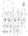
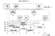
図1は、本実施例のワークフロー分析レポート作成システムのシステム構成を示す概念図である。 FIG. 1 is a conceptual diagram illustrating a system configuration of a workflow analysis report creation system according to the present embodiment.
図1に示すワークフロー分析レポート作成システムは、経営者等の顧客(「カスタマー」又は「ユーザ」)サイトである各病院(医療機関)サイトHCF1〜n側に設置され且つ顧客が所有する画像システム(「モダリティ」とも呼ぶ)10に接続されるサービスプロセッサ(SP)30と、このサービスプロセッサ30の例えば外部入力端子に外部データを出力可能に接続されるヒト追跡センサ20と、各病院サイトHCF1〜nに通信回線を介して接続されるサービスプロバイダ(アプリケーション・サービス・プロバイダ(ASP)も含まれる)等のサービスセンターSVC(「データセンター」とも呼ぶ)側に設置されるデータサーバ(DAS)(「サービスサーバ」とも呼ぶ)40と、サービスセンターSVCに通信回線を介して接続される顧客用のパーソナルコンピュータ(以下、ユーザPC(User PC)と呼ぶ)50とを有する。
The workflow analysis report creation system shown in FIG. 1 is an image system (owned by a customer) that is installed on each hospital (medical institution) site HCF1-n side, which is a customer (“customer” or “user”) site such as a manager. Service processor (SP) 30 connected to 10) (also called “modality”),
モダリティ10は、例えばCT装置、MRI装置、超音波診断装置、X線診断装置、核医学装置等の医用画像診断装置から構成される。本実施例では、例えば病院サイトHCF1〜n内のCT検査室に設置されるCT装置が例示される。CT装置は、例えば患者を載せる天板を進退自在に支持する寝台と、患者を載せた天板が進退される診断用開口部を有し且つその開口部内に進入された患者に対しX線照射によるCTスキャンを行うガントリと、CTスキャンに関する各種操作・制御信号をガントリ及び寝台に供給し且つCTスキャンで得られたX線データから患者のCT画像を再構成してモニタ上に表示する等の各種操作器及び画像処理装置等を有するコンソールとを有する。
The
ヒト追跡センサ20には、例えば映像、声、ICセンサ信号、通過スイッチ信号等の情報を検出し、この検出信号からモダリティ10を用いた検査に関わる医療スタッフ(技師、看護婦等)及び患者等の対象者となるヒト(動作主体者)OBの動きに関する情報(例えば、動作時間、動作場所、動作主体者の特定、動作の意味内容等)を分析可能なセンサであれば、いずれのタイプでもよく、例えばビデオカメラ(撮像装置)、ICタグ(「RFIDタグ」等とも呼ぶ)、ICチップ等が例示される。例えば、ビデオカメラの場合、病院サイトHCF1〜n内のモダリティ10が置かれる検査室の内外等の適宜位置に設置され、撮像されたヒトOBの映像信号をサービスプロセッサ30にその外部入力データとして供給する。ICタグの場合、ヒトOBが常時携帯し、病院サイトHCF1〜n内の適宜位置に設置されるRFIDリーダライタとの間の非接触通信によりヒトOBの通過等を検出しその通過信号等の検出信号をサービスプロセッサ30にその外部入力データとして供給する。本実施例では、ヒト追跡センサ20としては、例えばビデオカメラが例示される。
The
サービスプロセッサ30は、モダリティ10とは別体又は内蔵のプロセッサから構成され、機能上、メモリ上に配置される制御・処理プログラムを実行するCPUを含む処理部31と、メモリ(RAM/ROM)及びハードディスク等の記録媒体上に格納されるデータベース(DB)32と、処理部31からサービスセンター40へのデータ転送タイミングを制御する動作ON信号(割り込み信号)を発生するタイマ33とを有する。その他の構成要素としては、通信回線に接続される通信インターフェース(図示しない)等も含まれる。
The
処理部31は、CPUのプログラム実行により、ヒトOB(技師等)のモダリティ10に対するシステム操作に関する操作データを含むログ情報をモダリティ10から収集する(システム操作ログ収集ステップ311)。このログ情報には、モダリティ10からその装置情報、例えば装置のトラブル情報、故障情報、修理状況情報などの装置メンテナンス情報(以下、「メンテナンス情報」)に加え、装置の稼動状況や利用状況に関する情報(以下、「パフォーマンス情報」)の基本データが含まれる。パフォーマンス情報には、例えば「検査番号情報」、「検査開始時間」、「検査完了時間」、「X線照射開始時間」、「X線照射完了時間」、「再構成開始時間」、「再構成完了時間」、「検査技師名」、「放射線科医師名」、「依頼元名」、「検査種別」、「プラン設定種別」等の情報が含まれる。
The
また、処理部31は、CPUがメモリ上のプログラムを実行することにより、ヒト追跡センサ20からの外部入力データを収集する(情報収集ステップ312)。外部入力データには、例えば「患者入室時間」、「患者準備完了時間」、「患者退室時間」等が含まれる。
The
さらに、処理部31は、CPUのプログラム実行により、上記システム操作ログ収集ステップ311及び情報収集ステップ312で収集された両データに対し、「データの意味付け」を行ない、意味付けされたデータに対し時刻情報を付加して、「動作主体者(player)」と「ヒトOBの位置(location)」と「時間情報(time)」の関係を決定し、データベース32に一定期間(例えば、1日分の検査が終了するまで)蓄積させる(一定期間の情報蓄積ステップ313)。「データの意味付け」とは、例えば画像検査の場合、誰が検査をしたか、検査部位はどこか、検査種類は何かなどの分類によって、カテゴライズ化されるものを言う。ここで意味付けされた一連の情報は、サービスプロセッサ30内にある時計で、時刻情報と関連付けられる。
Further, the
処理部31は、CPUのプログラム実行により、上記データベース32の蓄積データをタイマ33からの動作ON信号を受けてサービスセンターSVCのデータサーバ40に転送する(蓄積データ転送ステップ314)。
The
サービスセンターSVCのデータサーバ40は、例えばインターネット上のWebサーバや電子メール機能等を有するPCサーバや専用サーバ等の1台又は複数台のコンピュータマシンで構成され、機能上、メモリ上に配置される制御・処理プログラムを実行するCPUを含む処理部41と、メモリ(RAM/ROM)及びハードディスク等の記録媒体上に格納されるデータベース(DB)42と、処理部42からユーザPC50へのレポート送信タイミングを制御する動作ON(割り込み信号)を発生するレポート送信タイマ43とを有する。その他の構成要素としては、通信回線に接続される通信インターフェース(図示しない)等も含まれる。制御・処理プログラムには、OSのほか、OS上で動作する通信プログラム、Webサーバソフトウェア等の各種アプリケーション・ソフトウェア等が含まれる。
The
また、このデータサーバDASは、アプリケーション・サービス・プロバイダ(ASP)により顧客向けに提供される。データサーバDASで利用可能なアプリケーション・ソフトウェアとして、シミュレーションソフト44がサーバに実装される。このシミュレーションソフト44は、ユーザPC50のWeb画面から入力されるデータを受信したときに、この入力データに基づいて、後述する各種シミュレーション分析を実行し、その分析結果をユーザPC50のWeb画面上に表示させることが可能となっている。
The data server DAS is provided to customers by an application service provider (ASP). As application software that can be used in the data server DAS,
処理部41は、CPUのプログラム実行により、サービスプロセッサ30から転送されてくるデータをデータベース42に蓄積し(蓄積データ保存ステップ411)、タイマ43からの動作ON信号を受けてデータベース42の蓄積データから情報を抽出し、これら情報を用いてインターネットのWeb上で閲覧可能なHTML又はXMLファイル形式のWebページからなるWebレポートとして「ワークフロー分析レポート(カスタマー向け定期レポート)」を作成し、電子メールでユーザPC50に送信する(情報抽出ステップ412)。
The
「ワークフロー分析レポート」には、例えば、部門内にある各部屋に患者が滞留している時間比率、各部屋にある装置稼働時間、装置間の稼働時間比較、装置利用時間、時間間隔毎のヒト追跡表示、部屋内のヒト出入り時間スケジュール、装置稼働時間スケジュール、各種基本テーブル情報、他病院サイトHCF1〜nの平均稼働率、他病院サイトHCF1〜nの平均稼働時間等が含まれる。 The “workflow analysis report” includes, for example, the time ratio that a patient stays in each room in the department, the device operating time in each room, the operating time comparison between devices, the device usage time, and the human for each time interval. A tracking display, a person entry / exit time schedule in the room, an apparatus operation time schedule, various basic table information, an average operation rate of other hospital sites HCF1 to HCF1, an average operation time of other hospital sites HCF1 to n, and the like are included.
ユーザPC50は、例えばインターネット上のWebサーバにより提供されるWebページを閲覧するWebブラウザ及びインターネット経由で電子メールを送受信させる電子メール機能を有し、機能上、メモリ上に配置される制御・処理プログラムを実行するCPUを含む処理部51を有する。その他、図示しなし構成要素として、ハードディスク等の記録装置、CRTや液晶ディスプレイ等の表示器、キーボードやマウス等の入力器、プリンタ等の出力器、及び通信回線に接続される通信インターフェース等も含まれる。制御・処理プログラムには、OSのほか、OS上で動作する通信プログラム、Webブラウザ、電子メールソフトウェア等の各種アプリケーション・ソフトウェア等が含まれる。
The
処理部51は、CPUのプログラム(Webブラウザ)実行により、データサーバ40により提供されるWebレポートであるワークフロー分析レポートをWeb画面上に表示する(レポート表示ステップ511)。また、この処理部51は、CPUのプログラム実行により、Web画面上に表示されるワークフロー分析レポートからユーザが所望するデータを抽出し、データサーバ40により提供されるシミュレーションソフト44に入力(エキスポート)し、そのシミュレーション分析結果を表示する(データ抽出ステップ512)。
The
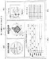
図2は、ユーザPC50の画面上で閲覧されるワークフロー分析レポートの表示例を示す。図2の例では、ワークフロー分析レポート(Web)レポートしてヒト追跡カスタマーレポートRP1が表示されている。このヒト追跡カスタマーレポートRP1には、部門内にある各部屋(検査室等)に患者が滞留している時間比率を表示する「患者の滞留時間」グラフW10と、各部屋にある装置の稼働時間、装置間の稼働時間比較、及び装置の利用時間等を表示する「装置利用時間」グラフW11と、時間間隔毎のヒトOBの追跡結果を表示する「トレーシング(追跡)」画面W12と、各種基本テーブル情報を表示する「テーブル」W13と、部屋内のヒト出入り時間スケジュールや装置稼働時間スケジュール等を表示する「各部屋のワークフロー」グラフW14とが設定されている。
FIG. 2 shows a display example of a workflow analysis report viewed on the screen of the
上記ワークフロー分析レポートには、その他、他病院サイトHCF1〜nの平均稼働率、他病院サイトHCF1〜nの平均稼働時間等のデータも、表示グラフやテーブル(データ)として表示可能となっている。 In the workflow analysis report, other data such as the average operation rate of the other hospital sites HCF1 to n, the average operation time of the other hospital sites HCF1 to n can be displayed as a display graph or a table (data).
上記ワークフロー分析レポートのうち、ユーザは、必要な分析結果のみを表示させることができる。また、ユーザは、図示しない「ユーザーコンフィグレーション画面」で各画面の表示条件に関するパラメータを可変設定することにより、ユーザPC50の表示画面上の好きな場所に好きなグラフやテーブルを表示させることが可能となっている。また、グラフやテーブルの表示方法として、色を変える等の設定も可能であり、例えば人の停滞時間の長い部分の色を変える等も可能である。
Among the workflow analysis reports, the user can display only necessary analysis results. In addition, the user can display a favorite graph or table at a favorite place on the display screen of the
図3は、ユーザPC50の画面上に表示されるシミュレーションソフト44を用いた分析表示例を示す。図3の例では、シミュレーションソフト44は、機能上、以下の表示機能を有するものを用いている。
FIG. 3 shows an analysis display example using the
1)「現在の分析結果」を表示する機能
これは、現在の検査スループット、検査時間、検査数等の分析結果を表示グラフとして切り替えて表示するものである。
1) Function for displaying “current analysis result” This is a function for switching and displaying analysis results such as the current inspection throughput, inspection time, and number of inspections as a display graph.
2)「プロセス変更後の分析結果予想」を表示する機能
これは、プロセス変更後にシミュレーションで予想される検査スループット、検査時間、検査数等の分析結果を表示グラフとして切り替えて表示するものである。これにより、例えば現在の検査スループットの表示と比較して評価可能となる。
2) Function for displaying “prediction of analysis result after process change” This is a function for switching and displaying analysis results such as inspection throughput, inspection time, number of inspections, etc. expected by simulation after process change as a display graph. Thereby, for example, evaluation can be made in comparison with the display of the current inspection throughput.
3)「ヒトトレーシング(ヒト追跡)の分析結果予想」を表示する機能
これは、ヒトOB毎の予想されるトレーシング分析結果を表示するものである。この分析結果は、時間毎の表示も可能である。この表示では、後述するように、ヒトOBの動作意味を入力し、どの動作にどれだけの時間を要しているかを表す表示グラフに変換することが可能である(詳細は図4参照)。
3) Function to display “predicted analysis result of human tracing” This is to display an expected tracing analysis result for each human OB. This analysis result can also be displayed for each hour. In this display, as will be described later, it is possible to input the operation meaning of the human OB and convert it into a display graph indicating how much time is required for which operation (refer to FIG. 4 for details).
4)「スケジュール」を表示する機能
これは、動作主体者毎のプロセススケジュールを表示するものである。このスケジュールは、時間毎の表示も可能である。
4) Function to display “schedule” This is to display a process schedule for each operation subject. This schedule can also be displayed hourly.
5)「プロセス変更」を入力する機能
これは、プロセスを変更することで、各種の分析結果の予想グラフやヒトトレース結果を表示するものである。プロセスとして変化可能なのは、患者が入室するタイミング、装置操作との連携方法、装置の置き方等である。これらのプロセスは、ユーザPC50のGUI上で設定し、シミュレーションデータとして利用される。
5) Function to input “process change” This is to display prediction graphs and human trace results of various analysis results by changing the process. What can be changed as a process is the timing at which the patient enters the room, the method of cooperating with the operation of the apparatus, the way of placing the apparatus, and the like. These processes are set on the GUI of the
6)「レイアウト変更」を入力する機能
これは、装置や部屋のレイアウトを変更することで、各種の分析結果の予想グラフやヒトトレース結果を表示するものである。これにより、レイアウトによる人件費コスト、収入アップの効果分析を表示可能になる。
6) Function for inputting “change layout” This is to display prediction graphs and human trace results of various analysis results by changing the layout of the apparatus and the room. As a result, it is possible to display the labor cost cost and the income increase effect analysis by the layout.
図4の例では、上記シミュレーションソフト44の表示機能により、シミュレーションレポート(Webレポート)RP2として、「現在の検査スループット」グラフW21、「検査スループット(予想)」グラフW22、「トレーシング(予想)」画面W23、「ワークフロー」グラフW24、「プロセス変更」ボタンBT1、「レイアウト変更」ボタンBT2、「分析」ボタンBT3、及び「グラフ変更」ボタンBT4が設定されている。
In the example of FIG. 4, the
上記シミュレーションソフト44を使った分析では、「トレーシング」表示機能において、ヒトの動作に関する設定が可能となっている。この詳細を図4を参照して説明する。
In the analysis using the
図4の例では、ヒトOBの動作意味D1として、例えば「患者を部屋へ搬入」の項目を設定し、この項目内に「ドアを開ける」、「部屋に入る」、「寝台を上げる又は下げる」、「部屋を出る」、「患者を連れて入る」、「患者を寝台にのせる」、「患者を固定する」、及びドアを閉める」がユーザ入力等により設定されている。このヒトOBの動作意味D1に対し、その動作主体者D3が誰であるかの関係が決定され、さらにそのヒトOBの動作に要した所要時間D2との関連も決定される。この場合の所要時間D2は、実データとして、例えばヒト追跡センサ20の検出信号(ビデオ画像等)内に埋め込まれている時間情報やSP内にある時計情報を基にしたタイムスタンプ情報が用いられる。
In the example of FIG. 4, for example, an item “Bring patient into room” is set as the operation meaning D1 of human OB, and “open the door”, “enter the room”, “raise or lower the bed” in this item “Exit the room”, “Take the patient in”, “Put the patient on the bed”, “Fix the patient”, and “Close the door” are set by user input or the like. With respect to the motion meaning D1 of the human OB, the relationship of who the motion subject D3 is is determined, and the relationship with the required time D2 required for the motion of the human OB is also determined. For the required time D2 in this case, as actual data, for example, time stamp information based on time information embedded in a detection signal (video image or the like) of the
このようにヒトOBの動作意味D1、所要時間D2、及び動作主体者D3が関連付けられた情報(以下、「ヒト動作情報」)は、1検査1セットとしてサービスプロセッサSP内に保管される。「ヒト動作情報」は、先のパフォーマンス情報と同様に、1日1回、サービスセンターSVCのデータサーバ40へデータ転送され、データサーバ40のデータベース42内に保存される。このデータベース42は、装置毎に、各日付の情報テーブルを持つことになる。データサーバ40は、データベース42の蓄積データを基に、カスタマー向け定期レポート(ワークフロー分析レポート)を電子メールで送ると同時に、Web上で全ての病院サイトHCF1〜nの定期レポートを表示する。レポート内容は、顧客の要望に応じて必要な情報に加工し、Webや電子メール等の手段を使って各顧客向けに情報を提供する。ユーザは、定期レポート内の情報を、シミュレーションソフト44内に取り込み、実データを用いたシミュレーションを行うことができる。
Thus, the information (hereinafter, “human motion information”) in which the motion meaning D1, the required time D2, and the motion subject D3 of the human OB are associated is stored in the service processor SP as one set of one examination. The “human motion information” is transferred to the
次に、図5を参照して、本実施例の全体動作を説明する。 Next, the overall operation of this embodiment will be described with reference to FIG.
まず、サービスプロセッサ30は、モダリティ10からの操作ログを収集する(ステップS1)一方、ヒト追跡センサ20からのヒトOBの動作に関する映像、声、ICセンサ信号、通過スイッチ情報などの情報を収集する(ステップS2)。
First, the
次いで、収集された信号は、一旦サービスプロセッサ30内で、データの意味付けを行う(ステップS3)。データの意味付けとは、例えば、画像検査の場合に、誰が検査をしたか、検査部位はどこか、検査種類は何かなどの分類によって、カテゴライズ化される。意味付けされた一連の情報は、サービスプロセッサ30内にある時計で、時刻情報との関連づけを得る(ステップS4)。その後、サービスプロセッサ30内に一旦保存される(ステップS5)。保存されたデータは、1検査単位で保存される。1日分の検査が終了したタイミングで、タイマ33からの動作ON信号を受けて、サービスプロセッサ30からデータが転送され(ステップS6)、サービスセンターSVCのデータサーバ40に受信され(ステップS7)、データベース42内に格納される(ステップS8)。
Next, the collected signals once make data meanings in the service processor 30 (step S3). For example, in the case of image inspection, the meaning of data is categorized by classification such as who performed the inspection, where the inspection site is, and what the inspection type is. The series of information given meaning is correlated with time information by a clock in the service processor 30 (step S4). Thereafter, it is temporarily stored in the service processor 30 (step S5). The stored data is stored in one examination unit. At the timing when the inspection for one day is completed, the operation ON signal from the
次いで、データサーバ40は、タイマ43からの動作ON信号を受けて、一定期間(例えば、1ヶ月、3ヶ月)蓄積されたデータを使って、Webレポート(前述の図2参照)を作成する(ステップS9)。Webレポートは、顧客のユーザPC50に対し電子メール等で送られ、これによりユーザPC50の画面上に表示される(ステップS10)と同時に、Web上でも閲覧可能となる。
Next, the
また、データサーバ40Sは、Web上で閲覧可能な実データ(検査数、検査時間など)をシミュレーションソフト44にエキスポート(Export)し(ステップS11)、シミュレーションソフト44でデータを取り込んで動作させ(ステップS12、S13)、これにより、そのシミュレーション分析結果(前述の図3参照)がユーザPC50の画面上に表示される(ステップS14)。
In addition, the data server 40S exports actual data (number of inspections, inspection time, etc.) that can be browsed on the Web to the simulation software 44 (step S11), and takes in the data with the
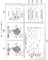
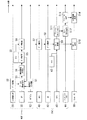
次に、図6を参照して、ワークフロー分析レポートで得られる各種時間情報の具体例を説明する。ここでは、モダリティ10としてCT装置、ヒト追跡センサ20としてビデオカメラの場合を例示している。
Next, specific examples of various time information obtained by the workflow analysis report will be described with reference to FIG. Here, a case where a CT apparatus is used as the
図6の例では、サービスプロセッサ30の外部入力データD10であるビデオカメラの映像情報から「患者が入室した時刻」、「患者の検査準備が完了した時刻」、「患者が退室した時刻」を得る。同様に、CT装置のコンソールの操作データ(システム操作ログ情報)D20から、サービスプロセッサ30を経由して、「技師が操作を開始した時刻」、「技師が操作を完了した時刻」、「Scanボタンを押した時刻」、「Scan終了時刻」を得る。ここで、「技師が操作を開始した時刻」、「技師が操作を完了した時刻」は、モダリティ10であるCT装置(コンソール)の操作データD20とヒト追跡センサ20の外部入力データD10(ビデオカメラの映像情報)との2種類の情報からタイムスタンプ情報を収集しても構わない。
In the example of FIG. 6, “time when the patient enters”, “time when the patient is ready for examination”, and “time when the patient leaves” are obtained from video information of the video camera which is the external input data D10 of the
これらのタイムスタンプ情報から、以下の各種時間情報が得られる(図6中の時刻t1〜t8及び時間T1〜T9参照)。
「患者準備時間」=「患者の検査準備が完了した時刻」−「患者が入室した時刻」
「患者待ち時間」=「Scanボタンを押した時刻」−「患者が入室した時刻」
「操作準備時間」=「Scanボタンを押した時刻」−「技師が操作を開始した時刻」
「スキャン時間」=「Scan終了時刻」−「Scanボタンを押した時刻」
「後処理時間」=「技師が操作を完了した時刻」−「Scan終了時刻」
「技師操作時間」=「技師が操作を完了した時刻」−「技師が操作を開始した時刻」
「検査時間」=「患者が退室した時刻」−「患者が入室した時刻」
「空き時間」=「次Scanボタンを押した時刻」−「技師が操作を完了した時刻」
From the time stamp information, the following various time information is obtained (see times t1 to t8 and times T1 to T9 in FIG. 6).
“Patient preparation time” = “Time when patient preparation for examination is completed” − “Time when patient enters room”
“Patient waiting time” = “Time when the scan button was pressed” − “Time when the patient entered the room”
“Operation preparation time” = “Time when the Scan button was pressed” − “Time when the engineer started operation”
“Scan time” = “Scan end time” − “Time when the Scan button is pressed”
“Post-processing time” = “Time when the engineer completes the operation” − “Scan end time”
“Engineer operation time” = “Time when engineer completes operation” − “Time when engineer starts operation”
“Examination time” = “Time when patient left” − “Time when patient entered”
“Free time” = “Time when the next Scan button was pressed” − “Time when the engineer completed the operation”
上記の時間情報を詳細に分析したり、他病院サイトHSF1〜nと比較したりすることで、どこに無駄・無理・ムラがあるか分析することができる。 By analyzing the above time information in detail or comparing it with other hospital sites HSF1 to HSFn, it is possible to analyze where there is waste / impossibility / unevenness.
例えば、他病院サイトHCF1〜nと比較して、「患者待ち時間」が長い場合、操作準備に手間取っているのか、それとも、患者の準備に手間取っているのか類推できる。そこで、更に、詳細な時間情報、即ち「操作準備時間」及び「患者準備時間」を分析することで、どこに問題がありそうか知ることができる。もし、「操作準備時間」が長く、操作準備に手間取っているとしたら、操作準備の方法に関するベストプラクティスの方法を提案する。もし、逆に、「患者準備時間」が長く、患者準備に手間取っているとしたら、患者準備に関するベストプラクティスの方法を提案する。また、準備手順が前後することで発生することが原因であれば、更なる分析のために、データサーバ40により提供されるWebサイトを訪問して詳細の情報収集が必要になる。
For example, when the “patient waiting time” is long compared to other hospital sites HCF 1 to n, it can be inferred whether it is time-consuming for preparation for operation or time-consuming for patient preparation. Therefore, by analyzing detailed time information, that is, “operation preparation time” and “patient preparation time”, it is possible to know where a problem is likely to occur. If the “operation preparation time” is long and it takes time to prepare for the operation, we propose a best practice method for the operation preparation method. Conversely, if the “patient preparation time” is long and the patient preparation is troublesome, the best practice method regarding patient preparation is proposed. In addition, if it is caused by the occurrence of preparation procedures, it is necessary to collect detailed information by visiting a Web site provided by the
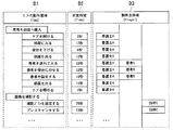
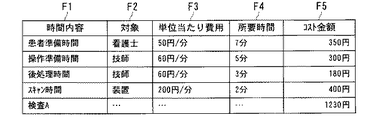
例えば、それぞれの時間内容に対して、対象と単位時間当たりの費用が分かっていれば、コスト金額は、図7に示すよう「時間内容」F1毎に「対象」F2、「単位時間当たり費用(円/分)」F3、「所要時間(分)」F4の各データから「コスト金額(円)」F5として求まり、これにより1検査当たりのコストを明確にできる。 For example, if the target and the cost per unit time are known for each time content, the cost amount is “target” F2, “cost per unit time (for each“ time content ”F1, as shown in FIG. Yen / minute) ”F3 and“ required time (minutes) ”F4 are obtained as“ cost amount (yen) ”F5, whereby the cost per examination can be clarified.
従って、本実施例によれば、病院サイトの部門毎に人(看護婦、技師等の医療スタッフ及び患者等)の動きを分析してシミュレーションを行うことができ、これにより患者や医療スタッフの動線に関するカスタマーレポートを提供できる。さらに、病院サイト側で実データを用いたシミュレーション分析も行うことができる。 Therefore, according to the present embodiment, it is possible to analyze and analyze the movement of people (medical staff such as nurses and technicians and patients) for each department of the hospital site. Can provide customer reports on lines. Furthermore, simulation analysis using actual data can be performed on the hospital site side.
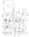
なお、上記実施例では、シミュレーションソフトをサービスセンター側のデータサーバに実装してあるが、本発明はこれに限らず、例えば図8に示すように、データサーバ40側のシミュレーションソフト44に加え、ユーザPC50側にもシミュレーションソフト52を実装してもよい。この構成においても、上記と同様の効果を得ることができる。
In the above embodiment, the simulation software is mounted on the data server on the service center side. However, the present invention is not limited to this, for example, in addition to the
また、上記実施例では、病院サイト外にサービスセンターのデータサーバが置かれる場合を想定しているが、本発明はこれに限らず、データサーバは病院サイト内に設置してもよい。 In the above embodiment, it is assumed that the data server of the service center is placed outside the hospital site. However, the present invention is not limited to this, and the data server may be installed in the hospital site.
さらに、上記実施例では、顧客サイトの代表として病院サイトを例示してあるが、本発明はこれに限らず、ワークフロー分析レポートを用いて部門の生産性を評価可能なものであれば、いずれの顧客サイトでも適用可能であり、例えば工場内の各部門等を例示できる。 Furthermore, although the hospital site is illustrated as a representative of the customer site in the above embodiment, the present invention is not limited to this, and any one can be used as long as the productivity of the department can be evaluated using the workflow analysis report. It can also be applied to a customer site. For example, each department in a factory can be exemplified.
なお、本発明は、代表的に例示した上述の実施形態に限定されるものではなく、当業者であれば、特許請求の範囲の記載内容に基づき、その要旨を逸脱しない範囲内で種々の態様に変形、変更することができる。これらの変更、変形例も本発明の権利範囲に属するものである。 It should be noted that the present invention is not limited to the above-described exemplary embodiments, and those skilled in the art will recognize various modes based on the description in the scope of the claims without departing from the spirit of the invention. Can be modified and changed. These changes and modifications also belong to the scope of rights of the present invention.
10 モダリティ(画像システム)
20 ヒト追跡センサ
30 サービスプロセッサ(SP)
31 処理部(サービスプロセッサ)
32 データベース(サービスプロセッサ)
33 タイマ
40 データサーバ(DAS)
41 処理部(データサーバ)
42 データベース(データサーバ)
43 レポート送信タイマ
44 シミュレーションソフト
50 ユーザPC
51 処理部(ユーザPC)
10 Modality (Image system)
20
31 Processing Unit (Service Processor)
32 database (service processor)
33
41 Processing unit (data server)
42 Database (data server)
43
51 Processing unit (user PC)
Claims (10)
前記医用施設内のセンサにより検出された人の動きに関する情報及び前記パフォーマンス情報を受信する手段と、
前記人の動きに関する情報及び前記パフォーマンス情報を保存するデータベース手段と、
前記データベースに記憶された前記人の動きに関する情報及び前記パフォーマンス情報に基づき、前記医用施設における作業の分析レポートを作成する処理手段とを有することを特徴とする情報処理装置。 An information processing device that collects performance information regarding the operation of a medical device in a remote medical facility via a network, analyzes the performance information, and provides a report of the analysis result,
Means for receiving information relating to human movement detected by a sensor in the medical facility and the performance information;
Database means for storing information relating to the movement of the person and the performance information;
An information processing apparatus comprising: processing means for creating an analysis report of work in the medical facility based on the information related to the movement of the person and the performance information stored in the database.
前記装置を用いた作業を行う作業者を含む対象者の動きに関する情報を検出するステップをさらに備え、
前記パフォーマンス情報を収集するステップは、
前記パフォーマンス情報に加え、センサの検出データを収集するステップと、
収集された前記データを前記情報処理装置に転送するステップとを有し、
前記ワークフロー分析レポートを作成するステップは、
前記サービスプロセッサからのデータを保存するステップと、
保存された前記データに基づき、前記対象者の動きに関連付けて前記装置を用いた作業に関するワークフローを分析し、該分析情報から前記ワークフロー分析レポートを作成するステップとを有することを特徴とするワークフロー分析レポート作成方法。 Collecting performance information relating to the operation of the device from a device located at a customer site; and analyzing the collected performance information to create a workflow analysis report for a customer relating to work using the device. A workflow analysis report creation method,
Further comprising the step of detecting information relating to the movement of the subject including the worker performing the work using the device,
Collecting the performance information comprises:
Collecting sensor detection data in addition to the performance information;
Transferring the collected data to the information processing apparatus,
The step of creating the workflow analysis report includes:
Storing data from the service processor;
Analyzing the workflow related to the work using the device in association with the movement of the subject based on the stored data, and creating the workflow analysis report from the analysis information. Report creation method.
前記分析情報もしくは前記サービスプロセッサで収集された情報を入力してシミュレーション分析を行うステップをさらに備えたことを特徴とするワークフロー分析レポート作成方法。 The workflow analysis report creation method according to claim 2,
A workflow analysis report creation method, further comprising a step of performing simulation analysis by inputting the analysis information or information collected by the service processor.
前記顧客サイトは複数存在し、
自顧客サイトで得られた分析情報に加え、複数の他顧客サイトで得られた分析情報をレポート表示するステップをさらに備えたことを特徴とするワークフロー分析レポート作成方法。 In the workflow analysis report creation method according to claim 2 or 3,
There are multiple customer sites,
A workflow analysis report creation method characterized by further comprising a step of displaying reports of analysis information obtained at a plurality of other customer sites in addition to the analysis information obtained at the customer site.
前記顧客サイトは、病院を含む医療機関であり、
前記装置は、前記医療機関の検査室に置かれるモダリティであり、
前記対象者は、前記モダリティを用いた検査を医療スタッフ及び該検査の被検者を含み、前記ワークフローは、前記モダリティを用いた検査に関するものであることを特徴とするワークフロー分析レポート作成方法。 The workflow analysis report creation method according to any one of claims 2 to 4,
The customer site is a medical institution including a hospital,
The device is a modality placed in a laboratory of the medical institution;
The workflow analysis report creation method, wherein the subject includes a medical staff and a subject of the examination for the examination using the modality, and the workflow relates to the examination using the modality.
前記サービスプロセッサからのパフォーマンス情報を分析して前記装置を用いた作業に関する顧客向けワークフロー分析レポートを作成する情報処理装置とを有するワークフロー分析レポート作成システムであって、
前記装置を用いた作業を行う作業者を含む対象者の動きに関する情報を検出するセンサをさらに備え、
前記サービスプロセッサは、
前記パフォーマンス情報に加え、前記センサの検出データを収集する手段と、
収集された前記データを前記情報処理装置に転送する通信手段とを有し、
前記情報処理装置は、
前記サービスプロセッサからのデータを保存するデータベース手段と、
保存された前記データに基づき、前記対象者の動きに関連付けて前記装置を用いた作業に関するワークフローを分析し、該分析情報から前記ワークフロー分析レポートを作成する処理手段とを有することを特徴とするワークフロー分析レポート作成システム。 A service processor that collects performance information about the operation of the device from the device located at the customer site;
A workflow analysis report creation system having an information processing device that analyzes performance information from the service processor and creates a workflow analysis report for a customer related to work using the device,
It further comprises a sensor for detecting information on the movement of the subject including the worker who performs work using the device,
The service processor is
Means for collecting detection data of the sensor in addition to the performance information;
Communication means for transferring the collected data to the information processing apparatus,
The information processing apparatus includes:
Database means for storing data from the service processor;
And a processing unit that analyzes a workflow related to work using the device in association with the movement of the subject based on the stored data and creates the workflow analysis report from the analysis information. Analysis report creation system.
前記分析情報もしくは前記サービスプロセッサで収集された情報を入力してシミュレーション分析を行うシミュレーション手段をさらに備えたことを特徴とするワークフロー分析レポート作成システム。 The workflow analysis report creation system according to claim 7,
A workflow analysis report creation system further comprising simulation means for performing simulation analysis by inputting the analysis information or information collected by the service processor.
前記顧客サイトは複数存在し、
自顧客サイトで得られた分析情報に加え、他顧客サイトで得られた分析情報をレポート表示する手段をさらに備えたことを特徴とするワークフロー分析レポート作成システム。 In the workflow analysis report creation system according to claim 7 or 8,
There are multiple customer sites,
A workflow analysis report creation system further comprising means for displaying a report of analysis information obtained at another customer site in addition to the analysis information obtained at the customer site.
前記顧客サイトは、病院を含む医療機関であり、
前記装置は、前記医療機関の検査室に置かれるモダリティであり、
前記対象者は、前記モダリティを用いた検査を医療スタッフ及び該検査の被検者を含み、前記ワークフローは、前記モダリティを用いた検査に関するものであることを特徴とするワークフロー分析レポート作成システム。 The workflow analysis report creation system according to any one of claims 7 to 9,
The customer site is a medical institution including a hospital,
The device is a modality placed in a laboratory of the medical institution;
The workflow analysis report creation system according to claim 1, wherein the subject includes a medical staff and a subject of the examination for the examination using the modality, and the workflow relates to the examination using the modality.
Priority Applications (1)
| Application Number | Priority Date | Filing Date | Title |
|---|---|---|---|
| JP2004108288A JP4550463B2 (en) | 2004-03-31 | 2004-03-31 | Workflow analysis report creation system and method, and information processing apparatus |
Applications Claiming Priority (1)
| Application Number | Priority Date | Filing Date | Title |
|---|---|---|---|
| JP2004108288A JP4550463B2 (en) | 2004-03-31 | 2004-03-31 | Workflow analysis report creation system and method, and information processing apparatus |
Publications (2)
| Publication Number | Publication Date |
|---|---|
| JP2005293301A true JP2005293301A (en) | 2005-10-20 |
| JP4550463B2 JP4550463B2 (en) | 2010-09-22 |
Family
ID=35326152
Family Applications (1)
| Application Number | Title | Priority Date | Filing Date |
|---|---|---|---|
| JP2004108288A Expired - Fee Related JP4550463B2 (en) | 2004-03-31 | 2004-03-31 | Workflow analysis report creation system and method, and information processing apparatus |
Country Status (1)
| Country | Link |
|---|---|
| JP (1) | JP4550463B2 (en) |
Cited By (5)
| Publication number | Priority date | Publication date | Assignee | Title |
|---|---|---|---|---|
| JP2007179464A (en) * | 2005-12-28 | 2007-07-12 | Toshiba Corp | Audit log management system |
| JP2007202678A (en) * | 2006-01-31 | 2007-08-16 | Toshiba Corp | Medical image photographing control device and medical image photographing system |
| JP2009517737A (en) * | 2005-11-23 | 2009-04-30 | ゼネラル・エレクトリック・カンパニイ | Real-time health care business decision support system and method by intelligent information collection and data modeling |
| JP2009217559A (en) * | 2008-03-11 | 2009-09-24 | Hitachi Ltd | Business management system, business management method, and management computer |
| JP2019133288A (en) * | 2018-01-30 | 2019-08-08 | 清水建設株式会社 | Method for evaluating physical distribution flow in facility and system for evaluating physical distribution flow in facility |
Families Citing this family (1)
| Publication number | Priority date | Publication date | Assignee | Title |
|---|---|---|---|---|
| JP6645957B2 (en) | 2016-12-16 | 2020-02-14 | 株式会社東芝 | Motion estimation method and motion estimation system |
Citations (11)
| Publication number | Priority date | Publication date | Assignee | Title |
|---|---|---|---|---|
| JPH05303615A (en) * | 1991-06-10 | 1993-11-16 | Toshiba Corp | Medical picture photographing system |
| JPH06337884A (en) * | 1993-03-31 | 1994-12-06 | Toshiba Corp | Work environment evaluation device |
| JPH07308321A (en) * | 1994-05-17 | 1995-11-28 | Hitachi Ltd | Graphics display object processing device, surgery simulation device, and rotational force generation device used in the device |
| JPH11120163A (en) * | 1997-10-17 | 1999-04-30 | Toyota Motor Corp | Operator motion simulation device and production line examination device |
| JP2001229292A (en) * | 1999-12-31 | 2001-08-24 | Ge Medical Technology Services Inc | Medical treatment and diagonosis system provided with on line and real time video training |
| JP2001292985A (en) * | 1999-11-29 | 2001-10-23 | General Electric Co <Ge> | Method and apparatus for communicating operating data to a system unit of a medical diagnostic system |
| JP2001319041A (en) * | 1999-11-19 | 2001-11-16 | Sanyo Electric Co Ltd | Management support system for medical institution and method for providing management support information to medical institution |
| JP2002157344A (en) * | 2000-06-01 | 2002-05-31 | Ge Medical Technology Services Inc | Method for automatically starting and stopping operation of operation data log record of medical image pickup device and system for the same |
| JP2002236744A (en) * | 2001-02-09 | 2002-08-23 | Toshiba Corp | Medical management support system |
| WO2003003265A1 (en) * | 2001-06-28 | 2003-01-09 | Exactcost, Inc. | Method and system for cost analysis and benchmarking in the healthcare industry |
| JP2004507941A (en) * | 2000-08-23 | 2004-03-11 | オーブ リミテッド | Data recorder |
-
2004
- 2004-03-31 JP JP2004108288A patent/JP4550463B2/en not_active Expired - Fee Related
Patent Citations (11)
| Publication number | Priority date | Publication date | Assignee | Title |
|---|---|---|---|---|
| JPH05303615A (en) * | 1991-06-10 | 1993-11-16 | Toshiba Corp | Medical picture photographing system |
| JPH06337884A (en) * | 1993-03-31 | 1994-12-06 | Toshiba Corp | Work environment evaluation device |
| JPH07308321A (en) * | 1994-05-17 | 1995-11-28 | Hitachi Ltd | Graphics display object processing device, surgery simulation device, and rotational force generation device used in the device |
| JPH11120163A (en) * | 1997-10-17 | 1999-04-30 | Toyota Motor Corp | Operator motion simulation device and production line examination device |
| JP2001319041A (en) * | 1999-11-19 | 2001-11-16 | Sanyo Electric Co Ltd | Management support system for medical institution and method for providing management support information to medical institution |
| JP2001292985A (en) * | 1999-11-29 | 2001-10-23 | General Electric Co <Ge> | Method and apparatus for communicating operating data to a system unit of a medical diagnostic system |
| JP2001229292A (en) * | 1999-12-31 | 2001-08-24 | Ge Medical Technology Services Inc | Medical treatment and diagonosis system provided with on line and real time video training |
| JP2002157344A (en) * | 2000-06-01 | 2002-05-31 | Ge Medical Technology Services Inc | Method for automatically starting and stopping operation of operation data log record of medical image pickup device and system for the same |
| JP2004507941A (en) * | 2000-08-23 | 2004-03-11 | オーブ リミテッド | Data recorder |
| JP2002236744A (en) * | 2001-02-09 | 2002-08-23 | Toshiba Corp | Medical management support system |
| WO2003003265A1 (en) * | 2001-06-28 | 2003-01-09 | Exactcost, Inc. | Method and system for cost analysis and benchmarking in the healthcare industry |
Cited By (6)
| Publication number | Priority date | Publication date | Assignee | Title |
|---|---|---|---|---|
| JP2009517737A (en) * | 2005-11-23 | 2009-04-30 | ゼネラル・エレクトリック・カンパニイ | Real-time health care business decision support system and method by intelligent information collection and data modeling |
| JP2007179464A (en) * | 2005-12-28 | 2007-07-12 | Toshiba Corp | Audit log management system |
| JP2007202678A (en) * | 2006-01-31 | 2007-08-16 | Toshiba Corp | Medical image photographing control device and medical image photographing system |
| JP2009217559A (en) * | 2008-03-11 | 2009-09-24 | Hitachi Ltd | Business management system, business management method, and management computer |
| JP2019133288A (en) * | 2018-01-30 | 2019-08-08 | 清水建設株式会社 | Method for evaluating physical distribution flow in facility and system for evaluating physical distribution flow in facility |
| JP7079108B2 (en) | 2018-01-30 | 2022-06-01 | 清水建設株式会社 | Facility flow line evaluation method and facility flow line evaluation system |
Also Published As
| Publication number | Publication date |
|---|---|
| JP4550463B2 (en) | 2010-09-22 |
Similar Documents
| Publication | Publication Date | Title |
|---|---|---|
| Partington et al. | Process mining for clinical processes: a comparative analysis of four Australian hospitals | |
| US7532942B2 (en) | Method and apparatus for generating a technologist quality assurance scorecard | |
| Stol et al. | Technology diffusion of anesthesia information management systems into academic anesthesia departments in the United States | |
| JP2004267273A (en) | Medical system | |
| JP5683280B2 (en) | Medical support system | |
| DE102008013051A1 (en) | Method and system for improved fault detection workflow | |
| JP2002092256A (en) | Automatic identification of training needs of medical staff | |
| CN111462874A (en) | Medical technology multimedia diagnosis guide system | |
| US20220199229A1 (en) | Method and system for enhancing medical ultrasound imaging devices with computer vision, computer aided diagnostics, report generation and network communication in real-time and near real-time | |
| Ngugi et al. | A multivariate statistical evaluation of actual use of electronic health record systems implementations in Kenya | |
| JP2006115921A (en) | Diagnosis support system | |
| Duncan et al. | A micro-analytic approach to understanding electronic health record navigation paths | |
| JP4550463B2 (en) | Workflow analysis report creation system and method, and information processing apparatus | |
| JP2002092181A (en) | Departmental data analysis and report for medical facility management | |
| Borycki et al. | Engineering the electronic health record for safety: a multi-level video-based approach to diagnosing and preventing technology-induced error arising from usability problems | |
| CN115280420A (en) | Finger print for radiologist | |
| CN118052298A (en) | Cognitive intervention system based on deep learning model | |
| JP2008129936A (en) | Hospital workflow analysis system and hospital workflow analysis method | |
| Dullabh et al. | The Technology Landscape of Patient-Centered Clinical Decision Support–Where Are We and What Is Needed? | |
| JP4774308B2 (en) | Depreciation cost calculation program and depreciation cost calculation method | |
| WO2025250476A1 (en) | Automated system for ultrasound imaging analysis, reporting, and reviewing | |
| Kusmasyri et al. | Development of an Android-Based CT Scan Examination Scheduling Information System at The Radiology Installation of Dr. H. Abdul Moeloek Hospital, Lampung Province | |
| Hu | A study on medical imaging equipment productivity and utilization | |
| Parthiban et al. | PULMOCHECK: A Flask-Based Deep Learning System for Lung Health Screening | |
| Humane et al. | A Small-Scale Simulation Model of an Emergency Department |
Legal Events
| Date | Code | Title | Description |
|---|---|---|---|
| A621 | Written request for application examination |
Free format text: JAPANESE INTERMEDIATE CODE: A621 Effective date: 20070328 |
|
| A977 | Report on retrieval |
Free format text: JAPANESE INTERMEDIATE CODE: A971007 Effective date: 20090803 |
|
| A131 | Notification of reasons for refusal |
Free format text: JAPANESE INTERMEDIATE CODE: A131 Effective date: 20090811 |
|
| A521 | Request for written amendment filed |
Free format text: JAPANESE INTERMEDIATE CODE: A523 Effective date: 20091013 |
|
| A02 | Decision of refusal |
Free format text: JAPANESE INTERMEDIATE CODE: A02 Effective date: 20100202 |
|
| A521 | Request for written amendment filed |
Free format text: JAPANESE INTERMEDIATE CODE: A523 Effective date: 20100430 |
|
| A911 | Transfer to examiner for re-examination before appeal (zenchi) |
Free format text: JAPANESE INTERMEDIATE CODE: A911 Effective date: 20100510 |
|
| TRDD | Decision of grant or rejection written | ||
| A01 | Written decision to grant a patent or to grant a registration (utility model) |
Free format text: JAPANESE INTERMEDIATE CODE: A01 Effective date: 20100608 |
|
| A01 | Written decision to grant a patent or to grant a registration (utility model) |
Free format text: JAPANESE INTERMEDIATE CODE: A01 |
|
| A61 | First payment of annual fees (during grant procedure) |
Free format text: JAPANESE INTERMEDIATE CODE: A61 Effective date: 20100708 |
|
| R150 | Certificate of patent or registration of utility model |
Ref document number: 4550463 Country of ref document: JP Free format text: JAPANESE INTERMEDIATE CODE: R150 Free format text: JAPANESE INTERMEDIATE CODE: R150 |
|
| FPAY | Renewal fee payment (event date is renewal date of database) |
Free format text: PAYMENT UNTIL: 20130716 Year of fee payment: 3 |
|
| S111 | Request for change of ownership or part of ownership |
Free format text: JAPANESE INTERMEDIATE CODE: R313117 |
|
| R350 | Written notification of registration of transfer |
Free format text: JAPANESE INTERMEDIATE CODE: R350 |
|
| S533 | Written request for registration of change of name |
Free format text: JAPANESE INTERMEDIATE CODE: R313533 |
|
| R350 | Written notification of registration of transfer |
Free format text: JAPANESE INTERMEDIATE CODE: R350 |
|
| LAPS | Cancellation because of no payment of annual fees |