JP2005292736A - Image forming apparatus - Google Patents
Image forming apparatus Download PDFInfo
- Publication number
- JP2005292736A JP2005292736A JP2004111529A JP2004111529A JP2005292736A JP 2005292736 A JP2005292736 A JP 2005292736A JP 2004111529 A JP2004111529 A JP 2004111529A JP 2004111529 A JP2004111529 A JP 2004111529A JP 2005292736 A JP2005292736 A JP 2005292736A
- Authority
- JP
- Japan
- Prior art keywords
- image
- image carrier
- transfer
- axial direction
- pattern
- Prior art date
- Legal status (The legal status is an assumption and is not a legal conclusion. Google has not performed a legal analysis and makes no representation as to the accuracy of the status listed.)
- Pending
Links
- 238000012546 transfer Methods 0.000 claims abstract description 319
- 238000001514 detection method Methods 0.000 claims abstract description 64
- 238000012545 processing Methods 0.000 abstract description 23
- 239000000969 carrier Substances 0.000 description 10
- 238000000034 method Methods 0.000 description 9
- 238000012937 correction Methods 0.000 description 8
- 230000015572 biosynthetic process Effects 0.000 description 6
- 239000003086 colorant Substances 0.000 description 4
- 238000010586 diagram Methods 0.000 description 3
- 230000003287 optical effect Effects 0.000 description 3
- 238000009434 installation Methods 0.000 description 2
- 238000005513 bias potential Methods 0.000 description 1
- 239000004020 conductor Substances 0.000 description 1
- 238000007796 conventional method Methods 0.000 description 1
- 238000003869 coulometry Methods 0.000 description 1
- 238000011161 development Methods 0.000 description 1
- 230000000694 effects Effects 0.000 description 1
- 230000006870 function Effects 0.000 description 1
- 238000011144 upstream manufacturing Methods 0.000 description 1
Images
Landscapes
- Electrostatic Charge, Transfer And Separation In Electrography (AREA)
- Control Or Security For Electrophotography (AREA)
Abstract
Description
本発明は、画像形成装置に係り、特に、光ビームで像担持体上を走査することにより画像を形成する画像形成装置に関する。 The present invention relates to an image forming apparatus, and more particularly to an image forming apparatus that forms an image by scanning an image carrier with a light beam.
従来より、レーザービーム等の光ビームにより走査する光ビーム走査装置を複数備え、記録用紙へカラー画像を形成するタンデム型の画像形成装置が知られている。このような画像形成装置として、各色(例えば、ブラック:K、シアン:C、マゼンタ:M、イエロー:Y)毎に、光ビーム走査装置及び像担持体からなる記録装置を複数配置し、中間転写体または中間転写体上に保持された記録媒体に、複数色のトナー像を重ねて転写し、これらを記録媒体上に定着してカラー画像を作成するものが知られている。 2. Description of the Related Art Conventionally, a tandem type image forming apparatus that includes a plurality of light beam scanning devices that scan with a light beam such as a laser beam and forms a color image on a recording sheet is known. As such an image forming apparatus, for each color (for example, black: K, cyan: C, magenta: M, yellow: Y), a plurality of recording devices including a light beam scanning device and an image carrier are arranged, and intermediate transfer is performed. There is known a technique in which a plurality of color toner images are transferred onto a recording medium held on a recording medium or an intermediate transfer body, and the color images are formed by fixing them on the recording medium.
このような画像形成装置では、例えば、記録媒体を搬送する中間転写体に沿って複数の像担持体を配列し、各像担持体の周囲に単色のトナー像を形成するための帯電装置、露光装置、現像機などのプロセス装置を備えるものがある。このような画像形成装置は、記録媒体を中間転写体により搬送しながら、光ビーム走査装置によって光ビームで像担持体を主走査方向に走査露光するとともに、像担持体が副走査方向に露光されるように回転することで副走査方向に走査露光されて、像担持体上に静電潜像を形成し、現像機によって可視化した各色のトナー像を転写器により順次重ねて転写し、記録媒体上で複数色のトナー像の重ね合わせを行うものである。そして、全ての色のトナー像を転写した後は、記録媒体を中間転写体から剥離して定着装置に搬送し、トナー像を記録媒体上に定着されてカラー画像として排出する。 In such an image forming apparatus, for example, a plurality of image carriers are arranged along an intermediate transfer member that conveys a recording medium, and a charging device for forming a monochromatic toner image around each image carrier, exposure Some devices include a process apparatus such as an apparatus and a developing machine. In such an image forming apparatus, while the recording medium is conveyed by the intermediate transfer member, the image carrier is scanned and exposed in the main scanning direction by the light beam by the light beam scanning device, and the image carrier is exposed in the sub-scanning direction. The image is scanned and exposed in the sub-scanning direction to form an electrostatic latent image on the image carrier, and the toner images of the respective colors visualized by the developing device are sequentially superimposed and transferred by a transfer device, and a recording medium A plurality of color toner images are superimposed on each other. After all color toner images have been transferred, the recording medium is peeled off from the intermediate transfer member and conveyed to a fixing device, where the toner image is fixed on the recording medium and discharged as a color image.
このような画像形成装置では、記録媒体上に形成されるカラー画像の色ずれや、記録媒体の搬送方向に対する画像の傾斜が生じないように、像担持体上のトナー像を各色毎に精度良く転写しなければならない。このため、ずれを補正するためのマーク(以下、レジコンマークという)を転写して、転写されたレジコンマークの位置をマーク検出装置で読み取る方法が知られている(例えば、特許文献1、特許文献2、及び特許文献3参照)。
In such an image forming apparatus, the toner image on the image carrier is accurately obtained for each color so as not to cause color misregistration of the color image formed on the recording medium and inclination of the image with respect to the conveyance direction of the recording medium. Must be transcribed. For this reason, a method is known in which a mark for correcting deviation (hereinafter referred to as a “registon mark”) is transferred and the position of the transferred resister mark is read by a mark detection device (for example,
この技術によれば、例えば、マーク信号形成装置からの出力信号に基づいて、露光装置により像担持体上に基準潜像を形成し、現像機により可視化したトナー像を中間転写体の非画像領域に転写して、レジコンマークを作成する。ついて、各色のレジコンマークの位置をマーク検出装置で読み取って、規定位置からのずれ量を検出し、これに基づいて露光装置の露光タイミングを変更することで、規定位置からのずれを補正する。このマーク検出装置としては、特許文献1ではCCDセンサが用いられ、特許文献2では、フォトインタラプタが用いられ、特許文献3では、光ドップラー装置が用いられている。
According to this technique, for example, based on an output signal from a mark signal forming device, a reference latent image is formed on an image carrier by an exposure device, and a toner image visualized by a developing machine is converted into a non-image area of an intermediate transfer member. Transfer to, and make a regicon mark. Next, the position of the registration control mark for each color is read by the mark detection device, the amount of deviation from the specified position is detected, and the exposure timing of the exposure apparatus is changed based on this to correct the deviation from the specified position. As this mark detection device, a CCD sensor is used in
しかしながら、上記技術では、中間転写体上の画像のずれ量を、CCDセンサ、フォトインタラプタ、光ドップラー装置等の光検出部で測定するので、中間転写体に直接トナー像を転写する必要がある。このため、トナーにより光検出部が汚染される恐れがあるという問題がある。また、画像形成装置内に、光検出部を設けるためのスペースを別途設ける必要があり、画像形成装置が大型化する恐れがあった。 However, in the above technique, the amount of image shift on the intermediate transfer member is measured by a light detection unit such as a CCD sensor, a photo interrupter, or an optical Doppler device, so that it is necessary to transfer the toner image directly to the intermediate transfer member. For this reason, there exists a problem that there exists a possibility that a photon detection part may be contaminated with toner. Further, it is necessary to provide a separate space for providing the light detection unit in the image forming apparatus, which may increase the size of the image forming apparatus.
そこで、上記従来技術とは異なる技術が開示されている(例えば、特許文献4参照)。 Therefore, a technique different from the conventional technique is disclosed (for example, see Patent Document 4).
特許文献4の技術によれば、中間転写体または転写ロールに相当する中間転写体の一部に導電性材料からなる導電部を設けて、複数の像担持体上の、導電部と対向する位置の各々に、色ずれ調整用の所定パターンの静電潜像を形成して、像担持体から中間転写体の導電部への電荷の移動を検出する。このように、複数の像担持体上に形成された静電潜像と中間転写体上の導電部とが接触するときの電荷の移動とタイミングとを検出することで、どの像担持体上の静電潜像がどのくらいずれているかを判別する。また、像担持体の軸線と平行な線上に潜像パターンを形成することで、像担持体の回転方向のずれ量や、各色の像担持体の軸線の方向がずれていることを検知する。
上記技術を用いると、像担持体の軸線の、被転写体の搬送方向に直交する方向に対するずれ量を求めることはできるが、像担持体の軸線と転写器との軸線とのずれを検出することは困難であり、像担持体の軸線と転写器の軸線とのずれによって、像担持体と被転写体とが接する位置と、被転写体と転写器との接する位置とがずれることで、被転写体上に形成される画像に濃度むらが発生する恐れがある。 When the above technique is used, it is possible to determine the amount of deviation of the axis of the image carrier relative to the direction perpendicular to the transfer direction of the transfer object, but detects the deviation between the axis of the image carrier and the axis of the transfer device. This is difficult, and the position where the image carrier and the transfer body are in contact with the position where the image carrier and the transfer body are in contact with each other due to the deviation between the axis of the image carrier and the axis of the transfer device. There is a possibility that density unevenness may occur in an image formed on the transfer target.
本発明は上記問題点を解決するためになされたものであり、簡易な構成で像担持体の軸線方向の、転写手段の軸線方向に対する傾きを示すスキュー量を得ることができる、画像形成装置を提供する事を目的とする。 The present invention has been made to solve the above-described problems, and an image forming apparatus capable of obtaining a skew amount indicating an inclination of the axial direction of the image carrier with respect to the axial direction of the transfer unit with a simple configuration. The purpose is to provide.
本発明の画像形成装置は、光ビームを主走査方向に走査する光ビーム走査手段と、予め帯電された状態で、前記光ビーム走査手段によって主走査方向に走査露光されるとともに、副走査方向に走査露光されるように所定の速度で回転される像担持体と、主走査方向及び副走査方向の異なる位置となるように一対のパターン画像が前記像担持体上に形成されるように前記光ビーム走査手段を制御する制御手段と、前記像担持体上に形成された前記パターン画像を被転写体に転写する転写手段と、前記像担持体上に形成された一対の前記パターン画像各々が前記転写手段によって被転写体に転写されるときの、前記転写手段と前記像担持体との間に流れる転写開始前の電流値からの変化量を一対の前記パターン画像各々について検出する検出手段と、前記検出手段によって検出された一対の前記パターン画像各々が転写されるときの前記変化量の差に基づいて、前記像担持体の軸線方向の、前記転写手段の軸線方向に対する傾きを示すスキュー量を演算する演算手段と、を備えている
本発明の画像形成装置の光ビーム走査手段は、画像データに基づいて、光ビームを主走査方向に走査する。像担持体は、予め均一に帯電されるとともに、帯電された状態で光ビーム走査手段によって主走査方向に走査露光される。像担持体は、副走査方向に所定の速度で回転することで、光ビーム走査手段によって副走査方向に走査露光される。制御手段は、光ビーム走査手段によって、主走査方向及び副走査方向の異なる位置となるように、一対のパターン画像が像担持体上に形成されるように、光ビーム走査手段を制御する。このため、像担持体上には、光ビーム走査手段によって、主走査方向及び副走査方向の異なる位置となるように、一対のパターン画像が形成される。主走査方向及び副走査方向に異なる位置となるように一対のパターン画像が形成された像担持体が所定の速度で回転することで、像担持体上の一対パターン画像各々は、副走査方向の間隔に応じて、順次転写手段の設けられた位置に到達し、転写手段によって、順次被転写体に転写される。被転写体の一例は、搬送ベルトや、中間転写体や、記録媒体等である。
The image forming apparatus of the present invention includes a light beam scanning unit that scans a light beam in the main scanning direction, and is preliminarily charged and scanned and exposed in the main scanning direction by the light beam scanning unit, and in the sub scanning direction. The image carrier rotated at a predetermined speed so as to be scanned and the light so that a pair of pattern images are formed on the image carrier so as to be in different positions in the main scanning direction and the sub-scanning direction. The control means for controlling the beam scanning means, the transfer means for transferring the pattern image formed on the image carrier to the transfer object, and the pair of pattern images formed on the image carrier each include Detection means for detecting, for each of the pair of pattern images, the amount of change from the current value before the start of transfer that flows between the transfer means and the image carrier when transferred to the transfer object by the transfer means. The skew amount indicating the inclination of the axial direction of the image carrier relative to the axial direction of the transfer means based on the difference in the change amount when each of the pair of pattern images detected by the detection means is transferred The light beam scanning unit of the image forming apparatus of the present invention scans the light beam in the main scanning direction based on the image data. The image carrier is uniformly charged in advance, and in the charged state, the image carrier is scanned and exposed in the main scanning direction by the light beam scanning unit. The image carrier is scanned and exposed in the sub-scanning direction by the light beam scanning unit by rotating at a predetermined speed in the sub-scanning direction. The control unit controls the light beam scanning unit so that the pair of pattern images are formed on the image carrier so that the light beam scanning unit has different positions in the main scanning direction and the sub scanning direction. For this reason, a pair of pattern images are formed on the image carrier by the light beam scanning means so as to be at different positions in the main scanning direction and the sub-scanning direction. By rotating the image carrier on which the pair of pattern images are formed so as to be in different positions in the main scanning direction and the sub-scanning direction at a predetermined speed, each of the pair of pattern images on the image carrier is in the sub-scanning direction. In accordance with the interval, the position sequentially reaches the position where the transfer means is provided, and the transfer means sequentially transfers the image to the transfer target. An example of the transfer target is a conveyance belt, an intermediate transfer member, a recording medium, or the like.
像担持体の軸線方向と転写手段の軸線方向とが同一である場合には、像担持体上に形成されたパターン画像が被転写体に転写される位置すなわち像担持体と被転写体との接線と、転写手段がパターン画像を被転写体に転写する位置すなわち被転写体と転写手段との接線とは、傾きの無い状態にある。このため、像担持体上に形成されたパターン画像は、均等に被転写体に転写されて、略均一な濃度となるように転写される。 When the axial direction of the image carrier and the axial direction of the transfer means are the same, the position where the pattern image formed on the image carrier is transferred to the transfer body, that is, the position between the image carrier and the transfer body The tangent and the position where the transfer unit transfers the pattern image to the transfer target, that is, the tangent between the transfer target and the transfer unit, are in a state of no inclination. For this reason, the pattern image formed on the image carrier is uniformly transferred to the transfer medium and transferred so as to have a substantially uniform density.
しかし、像担持体の軸線方向に対して転写手段の軸線方向が傾いている場合には、像担持体上に形成されたパターン画像が被転写体に転写される位置と、転写手段がパターン画像を被転写体に転写する位置とは、異なる。すなわち、像担持体と被転写体との接線と、被転写体と転写手段との接線は傾きの有る状態となる。このため、像担持体上に形成されたパターン画像は、均等に被転写体に転写されず、転写されるパターン画像の濃度が不均一となる恐れがある。 However, when the axial direction of the transfer unit is inclined with respect to the axial direction of the image carrier, the position where the pattern image formed on the image carrier is transferred to the transfer target and the transfer unit Is different from the position where the image is transferred to the transfer target. That is, the tangent line between the image bearing member and the transfer object and the tangent line between the transfer object and the transfer unit are inclined. For this reason, the pattern image formed on the image carrier is not evenly transferred to the transfer target, and the density of the transferred pattern image may be nonuniform.
そこで、検出手段は、像担持体上に形成された一対のパターン画像各々が転写手段によって被転写体に転写されるときの、転写手段と像担持体との間に流れる電流値を検出する。像担持体上のパターン画像の形成位置が被転写体を介して転写手段の位置に到達したときと、像担持体上のパターン画像の非形成領域が転写手段の位置に到達したときとでは、転写手段と像担持体との間に流れる電流値は変化する。検出手段は、パターン画像が転写手段によって被転写体に転写されるときの、転写手段と像担持体との間に流れる、転写開始前の電流値からの変化量を、一対のパターン画像各々について検出する。 Therefore, the detection unit detects a current value flowing between the transfer unit and the image carrier when each of the pair of pattern images formed on the image carrier is transferred to the transfer target by the transfer unit. When the formation position of the pattern image on the image carrier has reached the position of the transfer means via the transferred body, and when the non-formation area of the pattern image on the image carrier has reached the position of the transfer means, The value of the current flowing between the transfer means and the image carrier changes. The detecting means detects, for each of the pair of pattern images, the amount of change from the current value before starting transfer that flows between the transferring means and the image carrier when the pattern image is transferred to the transfer object by the transferring means. To detect.
この一対のパターン画像各々が転写手段によって被転写体に転写されるときの、一対のパターン画像各々の、転写手段と像担持体との間に流れる転写開始前の電流値からの変化量は、像担持体の軸線方向に対する転写手段の軸線方向の傾きが無い状態では、略同一の値を示す。しかし、像担持体の軸線方向に対する転写手段の軸線方向の傾きが有る状態では、像担持体上に形成されたパターン画像が被転写体に転写される位置すなわち像担持体と被転写体との接線と、転写手段がパターン画像を被転写体に転写する位置すなわち被転写体と転写手段との接線とは、異なるので、一対のパターン画像各々の、転写手段と像担持体との間に流れる転写開始前の電流値からの変化量は、異なる値となる。 When each of the pair of pattern images is transferred to the transfer target by the transfer unit, the amount of change from the current value before the transfer starts between the transfer unit and the image carrier of each of the pair of pattern images is In a state where there is no inclination in the axial direction of the transfer means with respect to the axial direction of the image carrier, substantially the same value is shown. However, in a state where the axial direction of the transfer means is inclined with respect to the axial direction of the image carrier, the position where the pattern image formed on the image carrier is transferred to the transfer body, that is, the position between the image carrier and the transfer body. Since the tangent and the position at which the transfer means transfers the pattern image to the transferred body, that is, the tangent line between the transferred body and the transfer means, are different, it flows between the transfer means and the image carrier of each of the pair of pattern images. The amount of change from the current value before the start of transfer is a different value.
演算手段は、検出手段によって検出された一対の前記パターン画像各々が転写されるときの変化量の差に基づいて、像担持体の軸線方向の、転写手段の軸線方向に対する傾きを示すスキュー量を演算する。 The computing means calculates a skew amount indicating an inclination of the axial direction of the image carrier relative to the axial direction of the transfer means based on a difference in change amount when each of the pair of pattern images detected by the detecting means is transferred. Calculate.
このように、本発明の画像形成装置は、主走査方向及び副走査方向に異なる位置となるように、一対のパターン画像を像担持体上に形成し、像担持体上に形成された一対のパターン画像各々を転写手段によって被転写体に転写するときの各パターン画像について、転写手段と像担持体との間に流れる転写開始前の電流値からの変化量を検出して、該検出した変化量の差に基づいて、像担持体の軸線方向の、転写手段の軸線方向に対する傾きを示すスキュー量を演算することができるので、簡易な構成で像担持体の軸線方向の、転写手段の軸線方向に対する傾きを示すスキュー量を得ることができる。 As described above, the image forming apparatus of the present invention forms a pair of pattern images on the image carrier so that the positions differ in the main scanning direction and the sub-scanning direction, and the pair of pattern images formed on the image carrier. For each pattern image when each pattern image is transferred to the transfer medium by the transfer means, the amount of change from the current value before the start of transfer flowing between the transfer means and the image carrier is detected, and the detected change Based on the difference in amount, the skew amount indicating the inclination of the image carrier in the axial direction with respect to the axial direction of the transfer means can be calculated, so that the axis of the transfer means in the axial direction of the image carrier can be calculated with a simple configuration. A skew amount indicating an inclination with respect to the direction can be obtained.
前記検出手段は、前記転写手段と一体的に設けられる。検出手段を転写手段と一体的に設けられるので、像担持体と転写手段との間に流れる電流値及び変化量を精度良く検出することができるとともに、検出手段と転写手段とを一対的に設けることで、画像形成装置本体の大型化を抑制することができる。 The detection means is provided integrally with the transfer means. Since the detection means is provided integrally with the transfer means, it is possible to accurately detect the current value and the amount of change flowing between the image carrier and the transfer means, and a pair of detection means and transfer means is provided. As a result, an increase in the size of the image forming apparatus main body can be suppressed.
前記パターン画像は前記像担持体の軸線方向の両端部に形成される。パターン画を像担持体の軸線方向の両端部、すなわち、光ビーム走査手段の主走査方向で且つ像担持体の軸線方向の両端部に形成することで、像担持体の軸線方向に対する転写手段の軸線方向の傾きを精度良く検出することができる。 The pattern image is formed at both ends in the axial direction of the image carrier. By forming pattern images at both ends in the axial direction of the image carrier, that is, at both ends in the main scanning direction of the light beam scanning means and in the axial direction of the image carrier, the transfer means with respect to the axial direction of the image carrier The inclination in the axial direction can be detected with high accuracy.
本発明の画像形成装置によれば、主走査方向及び副走査方向に異なる位置となるように、一対のパターン画像を像担持体上に形成し、像担持体上に形成された一対のパターン画像各々を転写手段によって被転写体に転写するときの各パターン画像について、転写手段と像担持体との間に流れる転写開始前の電流値からの変化量を検出して、該検出した変化量の差に基づいて、像担持体の軸線方向の、転写手段の軸線方向に対する傾きを示すスキュー量を演算することができるので、簡易な構成で像担持体の軸線方向の、転写手段の軸線方向に対する傾きを示すスキュー量を得ることができる、という効果を有する。 According to the image forming apparatus of the present invention, a pair of pattern images is formed on the image carrier so as to be in different positions in the main scanning direction and the sub-scanning direction, and the pair of pattern images formed on the image carrier. For each pattern image when each is transferred to the transfer object by the transfer means, the amount of change from the current value before the start of transfer flowing between the transfer means and the image carrier is detected, and the detected change amount Based on the difference, it is possible to calculate the skew amount indicating the inclination of the axial direction of the image carrier with respect to the axial direction of the transfer unit, so that the axial direction of the image carrier with respect to the axial direction of the transfer unit can be calculated with a simple configuration. There is an effect that a skew amount indicating an inclination can be obtained.
本発明の画像形成装置に係る、タンデム型のカラー画像形成装置の実施の形態を図面に基づき説明する。 An embodiment of a tandem type color image forming apparatus according to an image forming apparatus of the present invention will be described with reference to the drawings.
図1には、本実施の形態に係る画像形成装置10の主要構成の一例を示した。
FIG. 1 shows an example of the main configuration of the
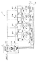
画像形成装置10は、搬送方向Yに搬送される中間転写体24を備えている。中間転写体24は、記録媒体を静電的に吸着して搬送方向Yに搬送するためのものである。また、画像形成装置10は、中間転写体24の搬送方向Yに沿って上流側から下流側に向かってタンデム状に配設される、Y画像形成ユニット30Y、M画像形成ユニット30M、C画像形成ユニット30C、及びK画像形成ユニット30Kを備えている。
The
Y画像形成ユニット30Y、M画像形成ユニット30M、C画像形成ユニット30C、及びB画像形成ユニット30Kは、各々、黄色トナー画像、マゼンタ色トナー画像、シアン色トナー画像、及び黒色トナー画像を中間転写体24に転写する。
The Y
Y画像形成ユニット30Yは、光ビーム走査装置14Y、帯電装置18Y、像担持体20Y、現像機22Y、及び転写器26Yを備えている。Y画像形成ユニット30Yと同様に、M画像形成ユニット30Mは、光ビーム走査装置14M、帯電装置18M、像担持体20M、現像機22M、及び転写器26Mを備えている。また、C画像形成ユニット30Cは、光ビーム走査装置14C、帯電装置18C、像担持体20C、現像機22C、及び転写器26Cを備えている。また、K画像形成ユニット30Kは、光ビーム走査装置14K、帯電装置18K、像担持体20K、現像機22K、及び転写器26Kを備えている。
The Y
また、画像形成装置10は、画像処理部12を備えている。画像処理部12は、入力された画像データを4色(K(黒)、C(シアン)、M(マゼンダ)、Y (イエロー))ごとにレーザ変調信号として光ビーム走査装置14K、光ビーム走査装置14C、光ビーム走査装置14M、光ビーム走査装置14Yへそれぞれ出力する。
In addition, the
光ビーム走査装置14Yは、レーザダイオードドライバ(以下、LDDという)16Yを備えており、画像処理部12から出力されたレーザ変調信号によりLDD16Yから射出される光ビームを変調し、像担持体20Yを主走査方向に走査する。
The light
像担持体の回転方向Bに所定の速度で回転される像担持体20Yは、帯電装置18Yにより一様に帯電された後、光ビーム走査装置14Yによって走査露光される。詳細には、光ビーム走査装置14Yによって主走査方向に走査露光されるとともに、副走査方向に走査露光されるように所定の速度で回転することで、像担持体20Yは主走査方向及び副走査方向に走査露光される。これによって、像担持体20Yに、画像処理部12に入力された画像データの黄色成分の画像に応じた静電潜像が形成される。像担持体20Yの静電潜像は、現像機22Yにより現像された後、像担持体20Yのトナー像が、転写器26Yによって、像担持体20Yの外周に中間転写体24が接する領域で、中間転写体24に転写される。
The
M画像形成ユニット30M、C画像形成ユニット30C、及びK画像形成ユニット30K各々に含まれる上記各構成は、各々、Y画像形成ユニット30Yに含まれる各構成と同様の機能を有する。
Each configuration included in each of the M
すなわち、M画像形成ユニット30M、C画像形成ユニット30C、K画像形成ユニット30Kにおいても、Y画像形成ユニット30Yと同様に、光ビーム走査装置14M、光ビーム走査装置14C、及び光ビーム走査装置14K各々により像担持体20M、像担持体20C、及び像担持体20K上が主走査方向に走査露光されるとともに、副走査方向に走査露光されるように所定の速度で像担持体の回転方向Bに回転することで、主走査方向及び副走査方向に走査露光されて静電潜像が形成される。更に、各像担持体20M、像担持体20C、及び像担持体20K各々の上に形成された静電潜像は、現像機22M、現像機22C、及び現像機22K各々により現像された後に、各像担持体20M、像担持体20C、及び像担持体20K上のマゼンダ、シアン、及び黒の各色のトナー像が、対応する転写器26M、転写器26C、及び転写器26Kによって中間転写体24に順次転写される。このようにして、中間転写体24上にカラー画像が形成される。
That is, in the M
各光ビーム走査装置14Y、光ビーム走査装置14M、光ビーム走査装置14C、及び光ビーム走査装置14K各々による光ビームの走査は、中間転写体24の搬送速度や、各像担持体20Y、像担持体20M、像担持体20C、及び像担持体20K間の距離等に応じて決定される所定の時間だけ間隔を置いて各々露光される。このとき、各像担持体20Y、像担持体20M、像担持体20C、及び像担持体20Kに対応する画像データが同一の場合、理想的な状態においては、中間転写体24上に形成される画像データに基づく画像の濃度は均一となる。しかしながら、実際には、各像担持体各々の取付位置ずれ、各転写器各々の取付位置ずれ、及び画像形成装置10全体の歪み等に起因して、像担持体の軸線方向に対して、転写器の軸線方向に傾きが生じる場合がある。
The light beam scanning by each of the light
このように像担持体の軸線方向に対して転写器の軸線方向が傾いている場合には、像担持体上に形成されたパターン画像が中間転写体に転写される位置と、転写手段がパターン画像を中間転写体に転写する位置とにずれが生じる。すなわち、像担持体と中間転写体24との接線と、中間転写体24と転写器との接線は傾きの有る状態となる。このため、像担持体上に形成されたパターン画像は、均等に中間転写体24に転写されず、転写されるパターン画像の濃度が不均一となる恐れがある。
In this way, when the axial direction of the transfer device is inclined with respect to the axial direction of the image carrier, the position where the pattern image formed on the image carrier is transferred to the intermediate transfer member and the transfer means There is a deviation from the position where the image is transferred to the intermediate transfer member. That is, the tangent line between the image carrier and the
そこで、画像処理部12は、複数の像担持体(20Y、20M、20C、20K)の各々の軸線方向に対する、各像担持体に対応して設けられた複数の転写器(26Y、26M、26C、26K)の軸線方向の傾きを示すスキュー量を求めるために、画像処理部12は、光ビーム走査装置14Y、光ビーム走査装置14M、光ビーム走査装置14C、及び光ビーム走査装置14K各々を、対応する像担持体20Y、像担持体20M、像担持体20C、及び像担持体20K各々に各像担持体の主走査方向及び副走査方向の異なる位置となるように一対のパターン画像を形成するように、制御する。
Therefore, the
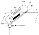
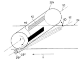
一対のパターン画像は、像担持体20Y、像担持体20M、像担持体20C、及び像担持体20K各々上の、軸線方向の両端に、副走査方向及び主走査方向の異なる位置となるように形成される画像である。本実施の形態では、図2に示すように、像担持体20Yの軸線方向50の一端から、像担持体20Yの軸線方向50の中心までの線画像としてのパターン画像40と、軸線方向50の中心から他端までの線画像としてパターン画像42とを、副走査方向の異なる位置となるように、形成するものとして説明する。なお、像担持体20M、像担持体20C、及び像担持体20K各々についても、同様に、一対のパターン画像40及びパターン画像42が形成される。
The pair of pattern images are positioned on the
なお、本実施の形態では、一対のパターン画像40及びパターン画像42は、像担持体20Yの軸線方向50の一端から、軸線方向50の中心までの線画像と、軸線方向50の中心から他端までの線画像として形成されるものとして説明するが、軸線方向50の両端でかつ主走査方向及び副走査方向の異なる位置となるように形成されればよく、このような形状に限られるものではない。
In the present embodiment, the pair of
一対のパターン画像40及びパターン画像42は、画像処理部12から、各光ビーム走査装置14Y、光ビーム走査装置14M、光ビーム走査装置14C、及び光ビーム走査装置14Kへ、パターン画像40及びパターン画像42を形成するためのレーザ変調信号が出力されることで、各光ビーム走査装置14Y、光ビーム走査装置14M、光ビーム走査装置14C、及び光ビーム走査装置14Kによって、各像担持体20Y、像担持体20M、像担持体20C、及び像担持体20K各々に形成される。
The pair of
この一対のパターン画像40及びパターン画像42の各像担持体20Y、像担持体20M、像担持体20C、及び像担持体20K各々への形成処理は、中間転写体24に記録媒体を吸着させて、画像処理部12に外部から入力された画像データに基づく画像を記録媒体上に形成する画像形成処理の実行以前に、複数の像担持体(20Y、20M、20C、及び20K)各々の軸線方向の、各像担持体に対応して設けられた複数の転写器(26Y、26M、26C、26K)各々の軸線方向に対する傾きを示すスキュー量を求めるために、画像データに基づく画像形成処理以前に実行される。
The paired
以下、説明を簡略化するために、Y画像形成ユニット30Yで行われる処理について説明する。なお、M画像形成ユニット30M、C画像形成ユニット30C、及びB画像形成ユニット30Kについても、Y画像形成ユニット30Yと同様の処理が行われる。
Hereinafter, in order to simplify the description, processing performed in the Y
画像処理部12の制御によって光ビーム走査装置14Yが制御されて、像担持体20Y上に一対のパターン画像40及びパターン画像42が形成された像担持体20Yが、像担持体20Yの軸線方向50を中心に、像担持体の回転方向Bに回転して、現像機22Yによって現像された後に、像担持体20Y上の一対のパターン画像の内の一方(ここではパターン画像40とする)の形成位置が、中間転写体24に接する位置に到達すると、転写器26Yによって一方のパターン画像40が中間転写体24に転写される。更に、像担持体20Yが像担持体の回転方向Bに回転して、現像された他方のパターン画像42の形成位置が中間転写体24に接する位置に到達すると、転写器26Yによって他方のパターン画像42が中間転写体24に転写される。
The light
この像担持体20Y上に形成された一対のパターン画像40及びパターン画像42を検出するために、転写器26Yは、検出部28Yを備えている。検出部28Yは、転写器26Yに一体的に設けられており、画像処理部12に接続されている。転写器26Yは、像担持体20Yと転写器26Yとの間の電位差によって、像担持体20Yと転写器26Yとの間を流れる電流値を検出するとともに、一対のパターン画像40及びパターン画像42各々が転写器26Yによって中間転写体24に転写されるときの、転写器26Yと像担持体20Yとの間に流れる、転写開始前の電流値からの変化量を検出する。
In order to detect the pair of
ここで、この像担持体20Yと転写器26Yとの間の電位差によって流れる電流について説明する。像担持体20Yは、所定速度で像担持体の回転方向Bに回転している。パターン画像40及びパターン画像42が形成された像担持体20Yが像担持体の回転方向Bに回転して、現像機22Yによって現像された後に、像担持体20Y上のパターン画像40及びパターン画像42の形成位置が、中間転写体24に接する位置に到達すると、転写器26Yによってパターン画像40の転写が行われている間、像担持体20Yと転写器26Yとの間の電位差に変化が生じる。
Here, the current that flows due to the potential difference between the
本実施の形態では、像担持体20Yは、帯電装置18Yによって略一様に約―800Vに帯電され、ついで、光ビーム走査装置14Yによって主走査方向に走査露光されてパターン画像40及びパターン画像42各々に応じた静電潜像が形成される。このとき、像担持体20Y上の該静電潜像が形成された露光部の電位は、―200V、非露光部の電位は−800Vとなる。更に、現像機22Yのバイアス電位を、―400Vとなるように設定して、マイナスに帯電したトナーが静電潜像の形成位置に付着することで、―200Vに帯電したトナーが付着したトナー像としてのパターン画像40及びパターン画像42各々が像担持体20Y上に現像される。
In the present embodiment, the
ここで、転写器26Yには、トナーと逆極性となる+700Vの電圧を予め印加する。―800Vの非露光部に、―200Vに帯電したトナーが付着したパターン画像40及びパターン画像42が形成された像担持体20Yが更に像担持体の回転方向Bに所定の速度で回転して、パターン画像40及びパターン画像42各々の形成位置が、中間転写体24と接する位置に到達すると、―800Vの非露光部から、―200Vのパターン画像40及びパターン画像42各々の形成位置が中間転写体24と接する位置に所定間隔(副走査方向の形成位置間隔)を空けて到達する。このため、各パターン画像40及びパターン画像42各々が中間転写体24に転写されるときには、像担持体20Yと転写器26Yとの間の電位差が変化して、像担持体20Yと転写器26Yとの間に流れる電流値に変化が生じる。そして、更に像担持体20Yが継続して像担持体の回転方向Bに回転して、転写器26Yの設置位置に、再度―800Vに帯電した非露光部が到達すると、像担持体20Yと転写器26Yとの間の電位差が更に変化して、像担持体20Yと転写器26Yとの間に流れる電流値に変化が生じ、元の、すなわち非露光部が転写器26Yの設置位置に到達したときの電位差となり、電流値が元に戻る。このように、像担持体20Y上に形成されたパターン画像40及びパターン画像42の中間転写体24への転写開始によって、転写開始前の電流値が変化し、更に転写終了することで、転写開始前の電流値に戻るので、像担持体20Y上に形成されたパターン画像40及びパターン画像42各々に基づいた2つの検出波形が検出される。検出部28Yによって、検出された2つの検出波形は、画像処理部12に出力される。
Here, a voltage of +700 V having a polarity opposite to that of the toner is applied in advance to the
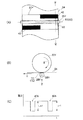
ここで、図3(A)に示すように、像担持体20Yの軸線方向50に対する転写器26Yの軸線方向52の傾きが無い場合、すなわちスキューが無い状態では、像担持体20Yと中間転写体24とが接する領域60に一致するように、転写器26Yが中間転写体24の他方の面(中間転写体24に対する像担持体20Yの設置位置が中間転写体24の表面方向とすると、中間転写体24の裏面方向)に接している。このため、図3(B)に示すように、像担持体20Yと中間転写体24とが接する位置70と、中間転写体24と転写器26Yとが接する位置72とは、像担持体20Y軸線方向50及び転写器26の軸線方向52において、一致するものとなる(図3(A)参照)。
Here, as shown in FIG. 3A, when there is no inclination in the
このため、像担持体20Yの軸線方向50と転写器26Yの軸線方向52とが傾きの無い状態、すなわち像担持体20Yと転写器26Yとの間にスキューの無い状態では、像担持体20Y上のパターン画像40とパターン画像42が中間転写体24に転写されるときに、検出部28Yは、図3(C)に示すように、パターン画像40に相当する検出波形40A、及びパターン画像42に相当する検出波形42Aを検出して画像処理部12へ出力する。この検出波形40A及び検出波形42A各々は、パターン画像40及びパターン画像42各々の中間転写体24への転写が開始されて、像担持体20Yと転写器26Yとの間に流れる転写開始前の電流値が変化し、パターン画像40及びパターン画像42各々の転写が終了して転写開始前の電流値に戻ることで、検出される検出波形である。このため、各パターン画像40及びパターン画像42が中間転写体24に転写されるときの、転写器26Yと像担持体20Yとの間に流れる転写開始前の電流値からの変化量を、検出波形に基づいて求めることができる。図3(C)に示すように、像担持体20Yの軸線方向50と転写器26Yの軸線方向52とが傾きの無い状態、すなわちスキューの無い状態では、パターン画像40及びパターン画像42各々が中間転写体24に転写されるときの、転写器26Yと像担持体20Yとの間に流れる転写開始前の電流値からの変化量は、双方ともh1であり、同一の値を示している。
Therefore, when the
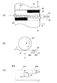
ここで、図4(A)に示すように、像担持体20Yの軸線方向50に対して、転写器26Yの軸線方向52に傾きが有る場合、すなわち像担持体20Yと転写器26Yとの間にスキューが有る状態では、像担持体20Yと中間転写体24とが接する領域60と、転写器26Yが中間転写体24の、中間転写体24に像担持体20Yが接する面に対して反対の面に接する領域62とは、重ならない領域が発生する。このため、中間転写体24の搬送方向Yに平行な図4(A)の図中W−W線に沿った断面図を示す図4(B)に示すように、像担持体20Yの軸線方向50に対して、転写器26Yの軸線方向52に傾きが有り、像担持体20Yと中間転写体24とが接する領域60と、転写器26Yが中間転写体24に接する領域62とが重ならない領域では、像担持体20Yと中間転写体24とが接する位置70と、中間転写体24と転写器26Yとが接する位置72とが、像担持体20Y軸線方向50及び転写器26の軸線方向52において、一致しない領域が発生する。
Here, as shown in FIG. 4A, when the
このため、像担持体20Yと中間転写体24とが接する位置70と、中間転写体24と転写器26Yとが接する位置72とがずれた量に応じて、ずれた量が大きくなる程、パターン画像40及びパターン画像42は、該ずれた位置に相当するパターン画像40及びパターン画像42の領域の濃度が薄い状態で中間転写体24に転写される。すなわち、像担持体20Yの軸線方向50に対する、転写器26の軸線方向52の傾きが大きくなるほど、中間転写体24に転写されるパターン画像40及びパターン画像42の濃度にむらが生じる。
For this reason, as the amount of deviation increases, the
このため、像担持体20Yの軸線方向50に対する転写器26Yの軸線方向52の傾きが有る場合には、パターン画像40及びパターン画像42各々が中間転写体24に転写されるときの、転写器26Yと像担持体20Yとの間に流れる転写開始前の電流値からの変化量は、異なる値となる。すなわち、像担持体20Yの軸線方向50に対する、転写器26の軸線方向52の傾きが大きくなるほど、像担持体20Yと中間転写体24とが接する位置と中間転写体24と転写器26Yとが接する位置72とがずれた、パターン画像40及びパターン画像42上の領域が大きくなるので、像担持体20Yの主走査方向及び副走査方向に異なる位置に形成されたパターン画像40及びパターン画像42各々が中間転写体24に転写されるときの、転写器26Yと像担持体20Yとの間に流れる転写開始前の電流値からの変化量は異なる値となる。
For this reason, when there is an inclination of the
図3(C)に示す例では、パターン画像40及びパターン画像42各々が中間転写体24に転写されるときの、転写器26Yと像担持体20Yとの間に流れる転写開始前の電流値からの変化量は、パターン画像40に相当する変化量がh1であり、パターン画像42に相当する変化量はh2であり、一対のパターン画像40とパターン画像42の転写時の転写開始前の電流値からの変化量に、h3の差が存在することが示されている。
In the example shown in FIG. 3C, from the current value before the start of transfer flowing between the
このように、像担持体20Yの軸線方向50が、検出部28Yの軸線方向52に対して傾いていると、像担持体20Y上に形成された、像担持体20Yの軸線方向52の両端部に主走査方向及び副走査方向が異なる位置となるように一対のパターン画像40パターン画像42各々が中間転写体24に転写されるときの、転写器26Yと像担持体20Yとの間に流れる転写開始前の電流値からの各々変化量は、互いに異なる値となる。また、像担持体20Yの軸線方向50に対する、転写器26の軸線方向52の傾きが大きくなるほど、像担持体20Yと中間転写体24とが接する位置と中間転写体24と転写器26Yとが接する位置72とがずれた、パターン画像40及びパターン画像42上の領域が大きくなるので、像担持体20Yの主走査方向及び副走査方向に異なる位置に形成されたパターン画像40及びパターン画像42各々が中間転写体24に転写されるときの、転写器26Yと像担持体20Yとの間に流れる転写開始前の電流値からの変化量には、像担持体20Yの軸線方向50の、検出部28Yの軸線方向52に対する傾きの量に応じて大きな差が発生する。
As described above, when the
同様に、M画像形成ユニット30M、C画像形成ユニット30C、及びB画像形成ユニット30Kにおいても、Y画像形成ユニット30Yと同様の処理が行われる。Y画像形成ユニット30Yと同様に、M画像形成ユニット30M、C画像形成ユニット30C、及びB画像形成ユニット30K各々の転写器26M、転写器26C、及び転写器26Kは、各々検出部28M、検出部28C、及び検出部28Kを含んで構成されており、各検出部28M、検出部28C、及び検出部28Kは、各々画像処理部12に接続されている。M画像形成ユニット30M、C画像形成ユニット30C、及びB画像形成ユニット30Kにおいても、Y画像形成ユニット30Yと同様の処理が行われて、検出部28M、検出部28C、及び検出部28K各々は、対応する像担持体と転写器との間の電位差による電流値を検出するとともに、対応する像担持体上に形成された一対のパターン画像40及びパターン画像42各々が中間転写体24に転写されるときの、転写器26Yと像担持体20Yとの間に流れる転写開始前の電流値からの変化量を示す、各パターン画像40及びパターン画像42に対応する検出波形を画像処理部12へ出力する。
Similarly, the M
画像処理部12は、主演算部30、補正量演算部32、及びスキュー量演算部34を備えている。
The
スキュー量演算部34は、検出部28Y、検出部28M、検出部28C、及び検出部28K各々から出力されたパターン画像40及びパターン画像42各々を示す検出波形に基づいて、各像担持体の軸線方向に対する、各像担持体に対応して設けられた各転写器の軸線方向の傾きを示すスキュー量を演算するための機能部である。
The skew
具体的には、スキュー量演算部34は、各検出部28Y、検出部28M、検出部28C、及び検出部28K各々から出力されたパターン画像40及びパターン画像42各々を示す検出波形に基づいて、各パターン画像40及びパターン画像42各々の転写開始前の電流値からの変化量の差を、各色毎に演算することで、各色毎の、像担持体の軸線方向に対する、各像担持体に対応する各転写器の軸線方向の傾きを示すスキュー量を演算する。
Specifically, the skew
例えば、図4(A)に示す像担持体20Yの軸線方向50に対する、転写器26Yの軸線方向52が傾きの有る状態にあるときの、図4(B)該像担持体20Yに形成されたパターン画像40及びパターン画像42各々を示すを示す検出波形40A及び検出波形40Bの転写開始前の電流値からの変化量h1と変化量h2との差h3を、像担持体20Yの軸線方向に対する転写器26Yの軸線方向の傾きを示すスキュー量として演算する。
For example, when the
補正量演算部32は、スキュー量演算部34から、検出部28Y、検出部28M、検出部28C、及び検出部28K各々から出力された検出波形に基づいて演算された、各色毎の像担持体の軸線方向に対する転写器の軸線方向の傾きを示すスキュー量に基づいて、各画像形成ユニット毎のずれ補正量を演算するためのものである。ずれ補正量は、例えば、各色毎のスキュー量に基づいて、複数の各像担持体(20Y、20M、20C、及び20K)の軸線方向と、各像担持体に対応する複数の転写器(26Y、26M、26C、及び26K)各々の軸線方向との傾きを抑制した、画像データに基づくレーザー変調信号を、画像処理部12から各Y画像形成ユニット30Y、M画像形成ユニット30M、C画像形成ユニット30C、及びB画像形成ユニット30Kへ出力するために、入力された画像データを補正するための値を示すものである。
The correction
ずれ補正量演算部32によって、各画像形成ユニット毎のずれ補正量が求められると、主演算部30は、入力された画像データをずれ補正量に基づいて所定の演算をして得られたデータを、図示を省略したラインメモリへ出力した後に、該ラインメモリから入力されたデータに応じて変調されたレーザ変調信号を、各色毎のLDD16Y、LDD16M、LDD16C、及びLDD16Kへ出力する。従って、画像処理部12から各色毎のY画像形成ユニット30Y、M画像形成ユニット30M、C画像形成ユニット30C、及びK画像形成ユニット30K各々へ、各色毎の像担持体(20Y、20M、20C、及び20K)の軸線方向に対する、各像担持体に対応する複数の転写器(26Y、26M、26C、及び26K)各々の軸線方向との傾きを示すスキュー量に基づいた補正が施された画像データに基づくレーザ変調信号が出力される。
When the shift correction
以上説明したように、本実施の形態の画像形成装置10によれば、所定速度で回転する像担持体上に、像担持体の軸線方向の両端部に、主走査方向及び副走査方向に異なる位置となるように一対のパターン画像40及びパターン画像42を形成し、像担持体上に形成された一対の各パターン画像40及びパターン画像42各々が転写器によって中間転写体24に転写されるときに、転写器に一体的に設けられた検出部において転写器と像担持体との間の電位差によって流れる電流値の変化量を示す、各パターン画像40及びパターン画像42各々に対応する検出波形を画像処理部12に出力する。
As described above, according to the
そして、各パターン画像40及びパターン画像42各々に対応する検出波形に基づいて、各パターン画像40及びパターン画像42各々を中間転写体24に転写するときの、転写開始前の電量値からの変化量の差を、像担持体の軸線方向と転写器の軸線方向との傾きを示すスキュー量として求めることができるので、簡易な構成で、像担持体の軸線方向と転写器の軸線方向との傾きを示すスキュー量を求めることができる。
Then, based on the detection waveform corresponding to each
また、像担持体の軸線方向と転写器の軸線方向との傾きを示すスキュー量を、該スキュー量を検出するための特別な検出装置を用いることなく、転写器と一体的に設けられた検出部による検出波形から求めることができる。 In addition, a skew amount indicating the inclination between the axial direction of the image carrier and the axial direction of the transfer device is detected integrally with the transfer device without using a special detection device for detecting the skew amount. It can obtain | require from the detection waveform by a part.
また、各色毎に設けられた複数の像担持体(20Y、20M、20C、及び20K)の軸線方向各々に対する、各像担持体に対応する複数の転写器(26Y、26M、26C、及び26K)各々の軸線方向各々との傾きを示す、各色毎のスキュー量を求めることができるので、各色間の像担持体(20Y、20M、20C、及び20K)の軸線方向のずれを、簡易な構成で、求めることも可能である。 Also, a plurality of transfer units (26Y, 26M, 26C, and 26K) corresponding to the respective image carriers with respect to the respective axial directions of the plurality of image carriers (20Y, 20M, 20C, and 20K) provided for the respective colors. Since the skew amount for each color indicating the inclination with respect to each axial direction can be obtained, the deviation in the axial direction of the image carrier (20Y, 20M, 20C, and 20K) between the colors can be simplified. It is also possible to ask.
また、本実施の形態の画像形成装置10では、転写器と一体的に検出器を設けたので、画像形成装置10の大型化を抑制することができる。
Further, in the
また、パターン画像を、像担持体の軸線方向の両端に設けたので、像担持体の軸線方向と転写器の軸線方向との傾きの検出精度を向上することができる。 Further, since the pattern images are provided at both ends in the axial direction of the image carrier, the detection accuracy of the inclination between the axial direction of the image carrier and the axial direction of the transfer device can be improved.
なお、本実施の形態では、像担持体20Yと転写器26Yと間の電位差によって、像担持体20Yと転写器26Yとの間を流れる電流値を検出するとともに、一対のパターン画像40及びパターン画像42各々が転写器26Yによって中間転写体24に転写されるときの、転写器26Yと像担持体20Yとの間に流れる、転写開始前の電流値からの変化量を検出するものとして説明したが、像担持体20Yと転写器26Yとの間の電圧値を検出するとともに、転写開始前の電圧値からの変化量を検出するようにしてもよい。この場合、検出波形は、パターン画像の転写が開始されてから終了するまでの電圧値の変化によって検出される検出波形となる。
In the present embodiment, the current value flowing between the
なお、本実施の形態では、転写器の軸線方向が像担持体の軸線方向に対して傾いている場合の例として、図4(A)及び図4(B)に示すように、転写器26Yの軸線方向52が中間転写体24に沿って搬送方向Yとなるように、像担持体20Yの軸線方向50が転写器26Yの軸線方向52に対して傾く場合を説明したが、転写器の軸線方向が像担持体の軸線方向に対する傾きは、転写器26Yの軸線方向52が中間転写体24に沿って搬送方向Yに傾く場合に限られるものではない。例えば、図5に示すように、像担持体20Yの軸線方向50に対して、転写器26Yの軸線方向52が離間する方向となるように、像担持体20Yの軸線方向50が転写器26Yの軸線方向52に対して傾く場合にも、適用可能である。
In the present embodiment, as an example of the case where the axial direction of the transfer device is inclined with respect to the axial direction of the image carrier, as shown in FIGS. 4A and 4B, the
すなわち、転写器26Yの軸線方向52が離間する方向となるように、像担持体20Yの軸線方向50が転写器26Yの軸線方向52に対して傾くことで、像担持体20Yと中間転写体24とが接する領域に対して、転写器26Yが中間転写体24に接する領域が少なくなる、すなわち、転写器26Yが中間転写体24に接する領域と離間する領域とが発生する。このため、像担持体20Y上に形成されたパターン画像40及びパターン画像42各々が中間転写体24に転写されるときの、像担持体20Yと検出部28Yとの間に流れる電流の転写開始前の電流値からの変化量は、互いに異なる値となる。このため、上記転写器26Yの軸線方向52が中間転写体24に沿って搬送方向Yとなるように、像担持体20Yの軸線方向50が転写器26Yの軸線方向52に対して傾く場合と同様に、像担持体の軸線方向に対する転写器の軸線方向の傾きを示すスキュー量を求めることができる。
That is, the
10 画像形成装置
12 画像処理部
14Y、14M、14C、14K 光ビーム走査装置
20Y、20M、20C、20K 像担持体
24 中間転写体
26Y、26M、26C、26K 転写器
28Y、28M、28C、28K 検出部
30 主演算部
34 スキュー量演算部
DESCRIPTION OF
Claims (3)
予め帯電された状態で、前記光ビーム走査手段によって主走査方向に走査露光されるとともに、副走査方向に走査露光されるように所定の速度で回転される像担持体と、
主走査方向及び副走査方向の異なる位置となるように一対のパターン画像が前記像担持体上に形成されるように前記光ビーム走査手段を制御する制御手段と、
前記像担持体上に形成された前記パターン画像を被転写体に転写する転写手段と、
前記像担持体上に形成された一対の前記パターン画像各々が前記転写手段によって被転写体に転写されるときの、前記転写手段と前記像担持体との間に流れる転写開始前の電流値からの変化量を一対の前記パターン画像各々について検出する検出手段と、
前記検出手段によって検出された一対の前記パターン画像各々が転写されるときの前記変化量の差に基づいて、前記像担持体の軸線方向の、前記転写手段の軸線方向に対する傾きを示すスキュー量を演算する演算手段と、
を備えた画像形成装置。 A light beam scanning means for scanning the light beam in the main scanning direction;
An image carrier that is pre-charged and scanned and exposed in the main scanning direction by the light beam scanning means and rotated at a predetermined speed so as to be scanned and exposed in the sub-scanning direction
Control means for controlling the light beam scanning means so that a pair of pattern images are formed on the image carrier so as to be at different positions in the main scanning direction and the sub-scanning direction;
Transfer means for transferring the pattern image formed on the image carrier to a transfer target;
From the current value before the start of transfer flowing between the transfer means and the image carrier when each of the pair of pattern images formed on the image carrier is transferred to the transfer object by the transfer means Detecting means for detecting a change amount of each of the pair of pattern images;
Based on the difference in the amount of change when each of the pair of pattern images detected by the detecting means is transferred, a skew amount indicating an inclination of the axial direction of the image carrier relative to the axial direction of the transferring means is determined. Computing means for computing;
An image forming apparatus.
Priority Applications (1)
| Application Number | Priority Date | Filing Date | Title |
|---|---|---|---|
| JP2004111529A JP2005292736A (en) | 2004-04-05 | 2004-04-05 | Image forming apparatus |
Applications Claiming Priority (1)
| Application Number | Priority Date | Filing Date | Title |
|---|---|---|---|
| JP2004111529A JP2005292736A (en) | 2004-04-05 | 2004-04-05 | Image forming apparatus |
Publications (1)
| Publication Number | Publication Date |
|---|---|
| JP2005292736A true JP2005292736A (en) | 2005-10-20 |
Family
ID=35325684
Family Applications (1)
| Application Number | Title | Priority Date | Filing Date |
|---|---|---|---|
| JP2004111529A Pending JP2005292736A (en) | 2004-04-05 | 2004-04-05 | Image forming apparatus |
Country Status (1)
| Country | Link |
|---|---|
| JP (1) | JP2005292736A (en) |
Cited By (2)
| Publication number | Priority date | Publication date | Assignee | Title |
|---|---|---|---|---|
| JP2010128375A (en) * | 2008-11-28 | 2010-06-10 | Brother Ind Ltd | Image forming apparatus |
| US9042754B2 (en) | 2011-10-05 | 2015-05-26 | Canon Kabushiki Kaisha | Image forming apparatus having latent image timing |
-
2004
- 2004-04-05 JP JP2004111529A patent/JP2005292736A/en active Pending
Cited By (2)
| Publication number | Priority date | Publication date | Assignee | Title |
|---|---|---|---|---|
| JP2010128375A (en) * | 2008-11-28 | 2010-06-10 | Brother Ind Ltd | Image forming apparatus |
| US9042754B2 (en) | 2011-10-05 | 2015-05-26 | Canon Kabushiki Kaisha | Image forming apparatus having latent image timing |
Similar Documents
| Publication | Publication Date | Title |
|---|---|---|
| US7865119B2 (en) | Color registration method and image forming apparatus | |
| US8446597B2 (en) | Image forming apparatus, image forming method, and computer program product including a secondary-transfer control unit that transfers a single-color image onto the intermediate transfer medium | |
| JP2005031263A (en) | Image forming apparatus | |
| JP5967957B2 (en) | Image forming apparatus | |
| JP2011180446A (en) | Image forming apparatus, and control method and program of the same | |
| JP2010134160A (en) | Image forming apparatus | |
| JP2007121923A (en) | Image forming apparatus, control method therefor, and program | |
| JP3698509B2 (en) | Color image forming apparatus | |
| JP4438484B2 (en) | Image forming apparatus | |
| JP4940780B2 (en) | Composite image and image forming apparatus | |
| JP2007196621A (en) | Signal processing device and imaging device | |
| JP4411339B2 (en) | Color image forming apparatus and control method thereof | |
| JP4997150B2 (en) | Color image forming apparatus | |
| KR101970464B1 (en) | image forming apparatus and color registration method thereof | |
| JP2005173253A (en) | Image forming apparatus | |
| JP2005292736A (en) | Image forming apparatus | |
| JP2010085422A (en) | Image forming apparatus | |
| JP2006091467A (en) | Image forming apparatus | |
| JP2004109682A (en) | Image forming apparatus and image position detecting device used in the same | |
| JP3307077B2 (en) | Tandem type color image forming apparatus | |
| JP6371585B2 (en) | Image forming apparatus | |
| JP4950562B2 (en) | Color image forming apparatus and control method thereof | |
| JP2007298868A (en) | Image forming apparatus and image forming method | |
| JP2011085870A (en) | Image forming apparatus | |
| JP2004287089A (en) | Chart for detecting color registration slippage, color registration slippage correction device using the chart and color image forming device |
Legal Events
| Date | Code | Title | Description |
|---|---|---|---|
| A621 | Written request for application examination |
Free format text: JAPANESE INTERMEDIATE CODE: A621 Effective date: 20070322 |
|
| A977 | Report on retrieval |
Free format text: JAPANESE INTERMEDIATE CODE: A971007 Effective date: 20091016 |
|
| A131 | Notification of reasons for refusal |
Free format text: JAPANESE INTERMEDIATE CODE: A131 Effective date: 20091027 |
|
| A02 | Decision of refusal |
Free format text: JAPANESE INTERMEDIATE CODE: A02 Effective date: 20100302 |