JP2005292674A - Display device - Google Patents
Display device Download PDFInfo
- Publication number
- JP2005292674A JP2005292674A JP2004110606A JP2004110606A JP2005292674A JP 2005292674 A JP2005292674 A JP 2005292674A JP 2004110606 A JP2004110606 A JP 2004110606A JP 2004110606 A JP2004110606 A JP 2004110606A JP 2005292674 A JP2005292674 A JP 2005292674A
- Authority
- JP
- Japan
- Prior art keywords
- liquid crystal
- crystal panel
- display
- operation target
- unit
- Prior art date
- Legal status (The legal status is an assumption and is not a legal conclusion. Google has not performed a legal analysis and makes no representation as to the accuracy of the status listed.)
- Granted
Links
Images


Landscapes
- Liquid Crystal (AREA)
- Arrangement Of Elements, Cooling, Sealing, Or The Like Of Lighting Devices (AREA)
- Liquid Crystal Display Device Control (AREA)
- Control Of Indicators Other Than Cathode Ray Tubes (AREA)
- Devices For Indicating Variable Information By Combining Individual Elements (AREA)
Abstract
Description
本発明は、CD等の挿入口やその周辺の操作部の照明を行う表示装置に関する。 The present invention relates to a display device that illuminates an insertion slot of a CD or the like and an operation unit in the vicinity thereof.
従来から、CD等の挿入口に重ねて液晶ディスプレイを配置し、CD等の再生時は挿入口を液晶ディスプレイで閉じた状態で所定の表示を行い、挿入口に対するCD等の挿抜時には液晶ディスプレイを傾倒させて挿入口を照明するようにした表示装置が知られている(例えば、特許文献1参照。)。この表示装置では、傾倒させた液晶ディスプレイ装置によって照明を行う際に、バックライトの輝度を最大に調光し、画面の色調を白色あるいはこれ以外の単色の画面に変更し、コントラスト変更によって視野方向を変えており、これらによって視認性を高める工夫がなされている。このようにしてCD等の挿抜時に液晶ディスプレイを照明装置として用いることにより、CD等の挿入口の照明のためだけに用いられるLED等の照明部をなくすことができ、装置の小型化や低コスト化を実現することができる。
ところで、上述した特許文献1に開示された表示装置では、白色あるいはそれ以外の単色に設定した液晶ディスプレイの全体を発光部として用いて、CD等の挿入口を含む筐体の前面を均等に照明しており、挿入口の位置をその形状等から利用者自身が探さなければならず、操作対象となる部位の位置確認が容易ではないという問題があった。例えば、挿入口の周辺にLED等の照明部を配置した場合と異なり、照明によって明るくなった筐体前面の中から利用者自身が見つけ出す必要がある。
By the way, in the display device disclosed in
本発明は、このような点に鑑みて創作されたものであり、その目的は、照明時に操作対象部位の位置確認を容易に行うことができる表示装置を提供することにある。 The present invention has been created in view of such a point, and an object of the present invention is to provide a display device capable of easily confirming the position of an operation target part during illumination.
上述した課題を解決するために、本発明の表示装置は、開閉可能であって発光部が配置された表示手段と、表示手段が開状態にあるときに現れ、閉状態にあるときに遮蔽される操作対象部位が操作対象面に配置された装置本体と、表示手段が開状態にあるときに、発光部によって操作対象部位に対する選択的な照明を行わせる照明制御手段とを備えている。装置本体の一の面全体に対して表示手段の発光部によって照明を行うのではなく、操作対象部位のみに対して選択的に照明を行うことにより、利用者自身が操作対象部位の位置を探すことなくその位置確認を容易に行うことができる。 In order to solve the above-described problems, a display device according to the present invention is capable of being opened and closed and appears when the light emitting unit is arranged, and when the display means is in an open state, and is shielded when it is in a closed state. The apparatus main body in which the operation target part is arranged on the operation target surface, and the illumination control means for selectively illuminating the operation target part by the light emitting unit when the display means is in the open state. Instead of illuminating the entire surface of the apparatus main body with the light emitting part of the display means, the user himself / herself searches for the position of the operation target part by selectively illuminating only the operation target part. The position can be easily confirmed without any problem.
また、上述した表示手段は、発光部としてのバックライトと、バックライトの発光面に配置された液晶パネルとを有することが望ましい。これにより、多くの装置に採用されているバックライト付きの液晶パネルを用いて操作対象部位に対する照明を行うことが可能になり、照明用の発光部を別に備える必要がなくなるため、部品点数の低減に伴うコストダウンが可能になる。 In addition, the display unit described above preferably includes a backlight as a light emitting unit and a liquid crystal panel disposed on a light emitting surface of the backlight. As a result, it becomes possible to illuminate the operation target part using a liquid crystal panel with a backlight, which is adopted in many apparatuses, and it is not necessary to provide a separate light emitting part for illumination, thereby reducing the number of parts. Cost reduction associated with this is possible.
また、上述した照明制御手段は、液晶パネルの表示内容を制御することにより、操作対象部位とそれ以外の部位のそれぞれに発光部から照射される光の明るさおよび色の少なくとも一方を変えることによって、操作対象部位に対する選択的な照明を行わせることが望ましい。あるいは、上述した照明制御手段は、液晶パネルの表示内容を制御することにより、発光部から操作対象部位あるいはその周辺に特定の映像(文字、図形、記号等)を内容とした光を照射することによって、操作対象部位に対する選択的な照明を行わせることが望ましい。液晶表示パネルの表示内容、すなわち表示する画像の内容を変更するだけであって、複雑な処理を行うことなく操作対象部位を強調して照明を行うことが可能になり、処理の簡略化が可能になる。 Further, the illumination control means described above controls at least one of the brightness and color of the light emitted from the light emitting unit to each of the operation target part and the other part by controlling the display content of the liquid crystal panel. It is desirable to cause selective illumination of the operation target part. Or the illumination control means mentioned above irradiates the light which specified the specific image | video (a character, a figure, a symbol, etc.) to the operation object part or its periphery from the light emission part by controlling the display content of a liquid crystal panel. Therefore, it is desirable to selectively illuminate the operation target part. By simply changing the display content of the liquid crystal display panel, that is, the content of the image to be displayed, it is possible to perform illumination by emphasizing the operation target part without performing complicated processing, thereby simplifying the processing. become.
また、上述した照明制御手段は、表示手段が開状態にあるときに、液晶パネルに備わった電極に印加する電圧を調整して液晶の配向角を変えて、発光部から操作対象部位に向けた光の照射量を増加させることが望ましい。これにより、操作対象部位に向けた光の照射量を増加させると同時に、液晶パネルから利用者に直接向かう光の量を減らすことが可能になるため、直接光が視界に入ることによって眩しくなることを防止することができる。 In addition, the illumination control unit described above adjusts the voltage applied to the electrodes provided in the liquid crystal panel when the display unit is in an open state to change the orientation angle of the liquid crystal and direct it from the light emitting unit to the operation target site. It is desirable to increase the amount of light irradiation. As a result, it is possible to reduce the amount of light directly directed from the liquid crystal panel to the user at the same time as increasing the amount of light directed toward the operation target part, so that the direct light enters the field of view and becomes dazzling. Can be prevented.
また、上述した液晶パネルは、バックライトに近い第1の液晶パネルと、バックライトから遠い第2の液晶パネルとが組み合わされており、照明制御手段は、表示手段が開状態にあるときに、第1および第2の液晶パネルのそれぞれに備わった電極に印加する電圧を調整して、第1の液晶パネルに含まれる液晶の配向角をバックライトの発光面とほぼ垂直に設定するとともに、第2の液晶パネルに含まれる液晶の配向角を変えて操作対象部位に向けた光の照射量を増加させることが望ましい。これにより、2枚の液晶パネルを用いた場合であっても1枚の液晶パネルを用いた場合と同様に、操作対象部位に向けた光の照射量を増加させると同時に、利用者に直接向かう光の量を減らすことができる。 Further, the liquid crystal panel described above is a combination of the first liquid crystal panel close to the backlight and the second liquid crystal panel far from the backlight, and the illumination control means is configured such that when the display means is in the open state, The voltage applied to the electrodes provided in each of the first and second liquid crystal panels is adjusted to set the orientation angle of the liquid crystal contained in the first liquid crystal panel substantially perpendicular to the light emitting surface of the backlight. It is desirable to change the alignment angle of the liquid crystal contained in the liquid crystal panel 2 to increase the amount of light irradiated toward the operation target site. As a result, even when two liquid crystal panels are used, the amount of light directed toward the operation target portion is increased and at the same time, as in the case where a single liquid crystal panel is used, and at the same time, direct to the user. The amount of light can be reduced.
また、上述した表示手段は、発光部と、発光部から照射される光の向きを可変する調整手段とを有し、照明制御手段は、表示手段が閉状態から開状態に変化したときに、調整手段を制御して発光部から照射される光を操作対象部位に向けることが望ましい。これにより、操作対象部位に対して選択的に照明を行うことが容易となる。 In addition, the display unit described above includes a light emitting unit and an adjusting unit that changes the direction of light emitted from the light emitting unit, and the illumination control unit is configured such that when the display unit changes from the closed state to the open state, It is desirable to control the adjusting means to direct the light emitted from the light emitting unit to the operation target site. Thereby, it becomes easy to selectively illuminate the operation target part.
また、上述した調整手段は、向きが変更可能なレンズであり、照明制御手段は、レンズの向きを変更することにより、発光部から照射される光を操作対象部位に向けることが望ましい。これにより、操作対象部位に対して確実に発光部の照射光を向けることができる。 In addition, the adjustment unit described above is a lens whose direction can be changed, and the illumination control unit preferably directs the light emitted from the light emitting unit to the operation target portion by changing the direction of the lens. Thereby, the irradiation light of a light emission part can be reliably directed with respect to the operation object site | part.
以下、本発明の電子機器操作装置を適用した一実施形態の表示装置について、図面を参照しながら詳細に説明する。 Hereinafter, a display device according to an embodiment to which an electronic device operating device of the present invention is applied will be described in detail with reference to the drawings.
〔第1の実施形態〕
図1は、第1の実施形態の表示装置の構成を示す図である。図1に示すように、本実施形態の表示装置100は、液晶パネル10、液晶駆動部12、バックライト14、バックライト駆動部16、表示処理部20、開閉検出部30、メディア挿入検出部32、照明パターン格納部34、制御部40を含んで構成されている。
[First Embodiment]
FIG. 1 is a diagram illustrating a configuration of a display device according to the first embodiment. As shown in FIG. 1, the
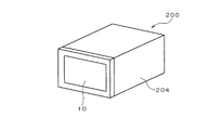
液晶パネル10は、開閉可能なノーズの一方の面に取り付けられており、所定の解像度で任意の色を表示することができる。図2および図3は、液晶パネルの設置状態を示す図である。図2および図3に示す車載装置200の一部として表示装置100が設けられている。この車載装置200は、開閉可能なノーズ202と、ノーズ202が取り付けられた装置本体204とを備えている。ノーズ202は、閉状態において、装置本体204の前面210の全体を覆っている。この閉状態において、運転者から見える面に液晶パネル10が設置されている。また、ノーズ202は、この閉状態から、液晶パネル10が次第に上向きとなるようにスライドし、最終的にほぼ水平となる開状態に移行させることができる。また、反対に開状態から閉状態に移行させることができる。これらの開閉動作は、駆動部によって自動的に行う場合の他に、利用者による手動で行われるようにしてもよい。ノーズ202が開状態のときに、装置本体204の前面210に設けられたCD挿入口220、MD挿入口230およびそれぞれに対応するイジェクトボタン222、232が外部に露出する。
The
液晶駆動部12は、液晶パネル10の全面に配置された電極に所定の駆動電圧を印加することにより液晶パネル10に対する表示制御を行う。バックライト14は、ノーズ202の内部であって液晶パネル10の背面に配置されており、液晶パネル10の全面に単色光からなる照明光を照射する。なお、バックライト14は、必ずしも液晶パネル10の背面全体に配置する必要はなく、液晶パネル10の縁近傍に配置してその照射光を反射シート等で反射して液晶パネル10に照射するようにしてもよい。バックライト駆動部16は、バックライト14の照明状態を制御する。表示処理部20は、バックライト駆動部16および液晶駆動部12を制御することにより、液晶パネル10に画像を表示するための処理を行う。例えば、描画データが入力されると、表示処理部20は、液晶駆動部12を制御して液晶パネル10にこの描画データに対応する画像を表示させる。また、表示処理部20は、バックライト駆動部16に指示を送って、所定の輝度でバックライト14を点灯させる。
The liquid
開閉検出部30は、ノーズ202の開閉状態を検出する。例えば、開閉状態に応じてオンオフ状態が切り替わるスイッチを開閉検出部30として用いることができる。あるいは、前面210の一部に開閉検出部30としての光センサを設け、ノーズ202の開閉状態を光センサによって検出するようにしてもよい。
The open /
メディア挿入検出部32は、CD挿入口220に対するCDの挿入状態と、MD挿入口230に対するMDの挿入状態を検出する。照明パターン格納部34は、CD挿入口220、MD挿入口230、イジェクトボタン222、232の形状および配置に対応した照明パターンを示す画像データを格納する。
The media
制御部40は、ノーズ202の開閉動作に伴う液晶パネル10の表示内容を変更する制御を含む表示装置100の全体動作を制御する。なお、この制御部40は、車載装置200の全体を制御する制御部を兼ねるようにしてもよいし、別々に設けるようにしてもよい。
The
上述した装置本体204の前面が操作対象面に、CD挿入口220、MD挿入口230、イジェクトボタン222、232が操作対象部位に、液晶パネル10、液晶駆動部12、バックライト14、バックライト駆動部16が表示手段に、バックライト14が発光部に、制御部40、照明パターン格納部34、表示処理部20が照明制御手段にそれぞれ対応する。
The front surface of the apparatus
本実施形態の表示装置はこのような構成を有しており、次に、その動作を説明する。図4は、ノーズ202の開閉動作に伴って行われる表示装置100の動作手順を示す流れ図である。
The display device of the present embodiment has such a configuration, and the operation thereof will be described next. FIG. 4 is a flowchart showing an operation procedure of the
制御部40は、開閉検出部30による検出状態を監視することにより、ノーズ202が開状態になったか否かを判定する(ステップ100)。開状態になっていない場合には否定判断が行われて、この判定が繰り返される。また、ノーズ202が閉状態から開状態に変化してその旨が開閉検出部30によって検出されるとステップ100の判定において肯定判断が行われる。
The
次に、制御部40は、照明パターン格納部34に格納されている照明パターンの画像データを読み出し(ステップ101)、メディア(CD、MD)がそれぞれ挿入口220、230に挿入された状態にあるか否かを判定する(ステップ102)。挿入中の場合には肯定判断が行われ、次に、制御部40は、CDあるいはMDが挿入中であることを未挿入の場合と識別できるようにするために、読み出した照明パターンの画像データの一部の色を変更する(ステップ103)。例えば、CDが挿入中の場合には、CD挿入口220とイジェクトボタン222の色が変更され、MDが挿入中の場合には、MD挿入口230とイジェクトボタン232の色が変更される。なお、CD、MDのいずれも未挿入の場合にはステップ102の判定において否定判断が行われ、ステップ103における色変更は行われない。
Next, the
次に、制御部40は、照明パターン格納部34から読み出された照明パターンの画像データに基づいて、あるいは色変更が行われた後の画像データに基づいて、照明パターンの描画処理を行い(ステップ104)、それまでの表示内容を照明パターンに変更する(ステップ105)。
Next, the
図5は、照明パターンの表示の具体例を示す図である。図5に示す表示例は、開状態にあるノーズ202を上から見た状態が示されており、上辺が装置本体204の前面210の下部に対応する。領域P1は、ノーズ202を閉じた状態においてCD挿入口220およびイジェクトボタン222を覆う部分P11と、MD挿入口230およびイジェクトボタン232を覆う部分P12を含んでおり、明るい色が付されている。例えば、CDとMDの両方が未挿入の場合には、領域P11、P12の両方が白色に設定される。また、CDのみが挿入されている場合には、一方の領域P11が赤色に設定され、他方の領域P12が白色に設定される。MDのみが挿入されている場合には、一方の領域P11が白色に設定され、他方の領域P12が赤色に設定される。CD、MDの両方が挿入されている場合には、領域P11、P12の両方が赤色に設定される。
FIG. 5 is a diagram illustrating a specific example of display of an illumination pattern. The display example shown in FIG. 5 shows a state in which the
また、領域P2、P3は、領域P1から次第に遠ざかる部分であり、次第に暗い色(例えば、灰色と黒色)が付されている。 The regions P2 and P3 are portions that gradually move away from the region P1, and are gradually darkened (for example, gray and black).
このような表示パターンを液晶パネル10に表示することにより、領域P1に対応するCD挿入口220、MD挿入口230、イジェクトボタン222、232とその周辺部分のみが明るく照明され、それ以外の部分は次第に暗くなるように照明される。
By displaying such a display pattern on the
次に、制御部40は、ノーズ202の閉状態を検出したか否かを判定する(ステップ106)。閉状態を検出していない場合には否定判断が行われ、ステップ102のメディアの挿入判定以降の処理が繰り返される。
Next, the
また、ノーズ202の閉状態が検出されるとステップ106において肯定判断が行われ、次に、制御部40は、それまで表示していた照明パターンを元の表示内容に戻した後(ステップ107)、ステップ100のノーズ202の開状態判定以降の処理が繰り返される。
When the closed state of the
このように、本実施形態の表示装置100では、装置本体204の前面210全体に対して液晶パネル10とバックライト14によって照明を行うのではなく、操作対象部位としてのCD挿入口220等のみに対して選択的に照明を行うことにより、利用者自身が操作対象部位の位置を探すことなくその位置確認を容易に行うことができる。
As described above, in the
また、多くの装置に採用されているバックライト付きの液晶パネル10を用いて操作対象部位に対する照明を行うことにより、照明用の発光部を別に備える必要がなくなるため、部品点数の低減に伴うコストダウンが可能になる。
Further, since the
また、液晶パネル10の表示内容、すなわち表示する画像の内容を変更するだけで、複雑な処理を行うことなく操作対象部位を強調して照明を行うことが可能になり、処理の簡略化が可能になる。
In addition, by simply changing the display content of the
図6は、照明パターンの表示の変形例を示す図である。図6に示す表示例は、図5に示した表示例と同様に、開状態にあるノーズ202を上から見た状態が示されている。領域P21は、ノーズ202を閉じた状態においてCD挿入口220およびイジェクトボタン222を覆う部分であり、この部分が独立して一つの領域を形成している。また、領域P22は、ノーズ202を閉じた状態においてMD挿入口230およびイジェクトボタン232を覆う部分であり、この部分が独立して一つの領域を形成している。これらの領域P21、P22は明るい色が設定されており、CDおよびMDの挿入状態に応じて色を異ならせる点については図5に示した表示例と同じである。また、領域P21、P22以外の領域P23には暗い色が設定されている。
FIG. 6 is a diagram illustrating a modification of the display of the illumination pattern. The display example shown in FIG. 6 shows a state in which the
ところで、上述した本実施形態の説明では、装置本体204の前面210にCD挿入口220やMD挿入口230等の開口が形成されている場合について説明したが、イジェクトボタン222、232のような操作部のみが装置本体204の前面210に配置されている場合についても本発明を適用することができる。このような場合にも、図5や図6に示す照明パターンを液晶パネル10に表示することで、各操作部を含むその周囲を照明することができる。
By the way, in the above description of the present embodiment, the case where openings such as the
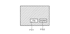
また、操作部を照明する場合に、操作部の内容に対応した文字を投影するようにしてもよい。図7〜図9は、操作部に文字を投影する場合の変形例を示す図である。図7に示すように装置本体204の前面210には、2つの操作ボタン240、244が備わっており、これらの操作ボタン240、244の下側には、それぞれの操作内容を示す「UP」の文字と「DOWN」の文字が描かれている。このような装置本体204の前面210に対して、図9に示す照明パターンの表示が行われる。領域P31、32のそれぞれは、ノーズ202を閉じたときに、操作ボタン240、244に対応する部分であり、明るい色が設定されているとともに、それぞれの中に投影したときに、図9に示すように「UP」あるいは「DOWN」の文字が操作ボタン240、244上に映し出されるように逆さ文字が含まれている。
Further, when the operation unit is illuminated, characters corresponding to the contents of the operation unit may be projected. 7 to 9 are diagrams illustrating modifications in the case where characters are projected on the operation unit. As shown in FIG. 7, two
このように、文字(あるいは操作内容がわかる図形や記号であってもよい)を含ませて装置本体204の前面210の操作対象箇所に対する照明を行うことにより、暗い場所での操作が容易となるだけでなく、操作指示の内容を確認することができる。
As described above, the operation in the dark place is facilitated by illuminating the operation target portion of the
また、本実施形態では、液晶の配向角については特に説明していないが、照明パターンを表示する際に装置本体204の前面210の該当箇所が最も明るくなるように配向角を制御することが望ましい。すなわち、図10に示すように、液晶パネル10は、電極付きの2枚のガラスG1、G2によって液晶Eを挟み込んだ構造を有しており、電極に電圧が印加されていない状態で、しかもバックライト14が消灯しているときには、外部から黒く見える。これに対して、図11に示すように、電極に電圧を印加した状態では液晶Eの配向角が変わってバックライト14の照射光を液晶パネル10を通して外部から見ることが可能になり、照明パターンが表示された液晶パネル10から光を照射することが可能になる。特に、液晶Eの配向角は、電極に印加する電圧を制御することにより調整可能であり、図12に示すように、水平状態に置かれた液晶パネル10から装置本体204の前面210に向けてバックライト14の照射光を導くことが可能になる。これにより、装置本体204の前面210の該当箇所を効率よく照明して視認性を向上させることができるとともに、液晶パネル10の照射光が直接運転者や助手席の搭乗者の視界に入ることを防止あるいは低減することが可能になり、眩しさを抑えることができる。
In this embodiment, the orientation angle of the liquid crystal is not particularly described, but it is desirable to control the orientation angle so that the corresponding portion of the
なお、液晶パネルの中には、2枚の液晶パネルを組み合わせることにより、立体視を実現したり、二人の利用者が異なる角度から別々の映像を見ることができるようにしたものがあるが、この場合にも各液晶パネルの液晶の配向角を制御することにより、照明による視認性を向上させることができる。例えば、図13に示すように2枚の液晶パネル10A、10Bが重ねて配置されているときに、図14に示すように、各液晶パネル10A、10Bに含まれる電極に印加する電圧を制御することにより、バックライトに近い側の液晶パネル10Bに含まれる液晶の配向角をバックライトの発光面とほぼ垂直に設定するとともに、バックライトから遠い側の液晶パネル10Aに含まれる液晶の配向角を変えて装置本体204の前面210の該当箇所に向けた光の照射量を増加させることができる。
Some LCD panels combine two LCD panels to achieve stereoscopic viewing and allow two users to see different images from different angles. Also in this case, the visibility by illumination can be improved by controlling the orientation angle of the liquid crystal of each liquid crystal panel. For example, when two
〔第2の実施形態〕
上述した第1の実施形態では液晶パネル10と組み合わされるバックライト14を発光部として用いて装置本体204の前面210の操作対象部位に対する照明を行ったが、その他の発光部を用いるようにしてもよい。
[Second Embodiment]
In the first embodiment described above, the
図15は、第2の実施形態の表示装置の構成を示す図である。図15に示すように、本実施形態の表示装置300は、発光部50、レンズ52、駆動部54、開閉検出部60、照明位置格納部62、制御部70を含んで構成されている。なお、この表示装置300が含まれる車載装置については図2や図3に示したものがそのまま適用される。但し、本実施形態では、液晶パネル10の代わりに発光部50が用いられているため、図2や図3に示したノーズ202に含まれる液晶パネル10を発光部50に置き換える必要がある。
FIG. 15 is a diagram illustrating a configuration of a display device according to the second embodiment. As shown in FIG. 15, the
発光部50は、LEDあるいはその他のランプが用いられており、所定範囲で放射状に光が照射される。例えば、発光部50は、各種のインジケータとして用いられる。レンズ52は、発光部50に近接して配置されており、発光部50から放射状に照射される光を集光する。駆動部54は、レンズ52の向きを機械的に調整する。ノーズ202の一方の面には複数の発光部50が備わっており、それぞれの発光部50に対応してレンズ52と駆動部54が設けられている。
The
開閉検出部60は、ノーズ202の開閉状態を検出する。照明位置格納部62は、ノーズ202を開状態にしたときに、発光部50の照射光を前面210に含まれる操作対象部位(CD挿入口220等)に向けるために必要なレンズ52の調整量に関するデータを格納する。
The open /
制御部70は、表示装置300の全体制御を行うとともに、ノーズ202の開閉動作に伴ってレンズ52の向きを変更する制御を行う。具体的には、開閉検出部60によってノーズ202が閉状態から開状態に移行したことが検出されると、制御部70は、照明位置格納部62からレンズ52の調整量に関するデータを読み出し、このデータに基づいて駆動部54を制御してレンズ52の向きを変更する。例えば、ノーズ202が閉状態にあるときに、図16に示すレンズ52の向きに設定されていたものが、ノーズ202が開状態になったときに、図17に示すレンズの向きに変更される。これにより、発光部50から照射された光によって、装置本体204の前面210の操作対象部位に対してスポット的に照射を行うことが可能になり、操作対象部位の視認性を向上させることができる。
The
上述した発光部50、レンズ52、駆動部54が表示手段に、制御部70,照明位置格納部62が照明制御手段に、レンズ52、駆動部54が調整手段にそれぞれ対応する。
The
なお、本発明は上記実施形態に限定されるものではなく、本発明の要旨の範囲内において種々の変形実施が可能である。例えば、上述した実施形態では、車載装置200に含まれる表示装置100、300について説明したが、車載装置200以外の各種の装置に含まれる表示装置について本発明を適用することができる。
In addition, this invention is not limited to the said embodiment, A various deformation | transformation implementation is possible within the range of the summary of this invention. For example, in the above-described embodiment, the
10 液晶パネル
12 液晶駆動部
14 バックライト
16 バックライト駆動部
20 表示処理部
30、60 開閉検出部
32 メディア挿入検出部
34 照明パターン格納部
40、70 制御部
50 発光部
52 レンズ
54 駆動部
62 照明位置格納部
DESCRIPTION OF
Claims (8)
前記表示手段が開状態にあるときに現れ、閉状態にあるときに遮蔽される操作対象部位が操作対象面に配置された装置本体と、
前記表示手段が開状態にあるときに、前記発光部によって前記操作対象部位に対する選択的な照明を行わせる照明制御手段と、
を備えることを特徴とする表示装置。 Display means that is openable and closable and in which the light emitting part is arranged;
An apparatus main body in which an operation target portion that appears when the display means is in an open state and is shielded when the display means is in a closed state is disposed on the operation target surface;
Illumination control means for selectively illuminating the operation target site by the light emitting unit when the display means is in an open state;
A display device comprising:
前記表示手段は、前記発光部としてのバックライトと、前記バックライトの発光面に配置された液晶パネルとを有することを特徴とする表示装置。 In claim 1,
The display device includes a backlight as the light-emitting unit and a liquid crystal panel disposed on a light-emitting surface of the backlight.
前記照明制御手段は、前記液晶パネルの表示内容を制御することにより、前記操作対象部位とそれ以外の部位のそれぞれに前記発光部から照射される光の明るさおよび色の少なくとも一方を変えることによって、前記操作対象部位に対する選択的な照明を行わせることを特徴とする表示装置。 In claim 2,
The illumination control unit controls at least one of brightness and color of light emitted from the light emitting unit to each of the operation target part and the other part by controlling display contents of the liquid crystal panel. A display device that selectively illuminates the operation target part.
前記照明制御手段は、前記液晶パネルの表示内容を制御することにより、前記発光部から前記操作対象部位あるいはその周辺に特定の映像を内容とした光を照射することによって、前記操作対象部位に対する選択的な照明を行わせることを特徴とする表示装置。 In claim 2,
The illumination control means controls the display content of the liquid crystal panel, thereby irradiating the operation target site or its surroundings with light having a specific image as a content, thereby selecting the operation target site. A display device characterized by performing a general illumination.
前記照明制御手段は、前記表示手段が開状態にあるときに、前記液晶パネルに備わった電極に印加する電圧を調整して液晶の配向角を変えて、前記発光部から前記操作対象部位に向けた光の照射量を増加させることを特徴とする表示装置。 In any one of Claims 2-4,
The illumination control unit adjusts a voltage applied to an electrode provided in the liquid crystal panel when the display unit is in an open state to change the orientation angle of the liquid crystal, and directs the light emitting unit toward the operation target site. A display device characterized by increasing the amount of irradiated light.
前記液晶パネルは、前記バックライトに近い第1の液晶パネルと、前記バックライトから遠い第2の液晶パネルとが組み合わされており、
前記照明制御手段は、前記表示手段が開状態にあるときに、前記第1および第2の液晶パネルのそれぞれに備わった電極に印加する電圧を調整して、前記第1の液晶パネルに含まれる液晶の配向角を前記バックライトの発光面とほぼ垂直に設定するとともに、前記第2の液晶パネルに含まれる液晶の配向角を変えて前記操作対象部位に向けた光の照射量を増加させることを特徴とする表示装置。 In any one of Claims 2-4,
The liquid crystal panel is a combination of a first liquid crystal panel close to the backlight and a second liquid crystal panel far from the backlight,
The illumination control means is included in the first liquid crystal panel by adjusting a voltage applied to an electrode provided in each of the first and second liquid crystal panels when the display means is in an open state. The orientation angle of the liquid crystal is set substantially perpendicular to the light emitting surface of the backlight, and the amount of light irradiated toward the operation target site is increased by changing the orientation angle of the liquid crystal contained in the second liquid crystal panel. A display device.
前記表示手段は、前記発光部と、前記発光部から照射される光の向きを可変する調整手段とを有し、
前記照明制御手段は、前記表示手段が閉状態から開状態に変化したときに、前記調整手段を制御して前記発光部から照射される光を前記操作対象部位に向けることを特徴とする表示装置。 In claim 1,
The display unit includes the light emitting unit and an adjusting unit that changes a direction of light emitted from the light emitting unit.
The illumination control unit controls the adjustment unit to direct light emitted from the light emitting unit toward the operation target part when the display unit changes from a closed state to an open state. .
前記調整手段は、向きが変更可能なレンズであり、
前記照明制御手段は、前記レンズの向きを変更することにより、前記発光部から照射される光を前記操作対象部位に向けることを特徴とする表示装置。
In claim 7,
The adjusting means is a lens whose direction can be changed,
The display device according to claim 1, wherein the illumination control unit directs light emitted from the light emitting unit toward the operation target portion by changing a direction of the lens.
Priority Applications (1)
| Application Number | Priority Date | Filing Date | Title |
|---|---|---|---|
| JP2004110606A JP4640759B2 (en) | 2004-04-05 | 2004-04-05 | Display device |
Applications Claiming Priority (1)
| Application Number | Priority Date | Filing Date | Title |
|---|---|---|---|
| JP2004110606A JP4640759B2 (en) | 2004-04-05 | 2004-04-05 | Display device |
Publications (2)
| Publication Number | Publication Date |
|---|---|
| JP2005292674A true JP2005292674A (en) | 2005-10-20 |
| JP4640759B2 JP4640759B2 (en) | 2011-03-02 |
Family
ID=35325629
Family Applications (1)
| Application Number | Title | Priority Date | Filing Date |
|---|---|---|---|
| JP2004110606A Expired - Fee Related JP4640759B2 (en) | 2004-04-05 | 2004-04-05 | Display device |
Country Status (1)
| Country | Link |
|---|---|
| JP (1) | JP4640759B2 (en) |
Citations (11)
| Publication number | Priority date | Publication date | Assignee | Title |
|---|---|---|---|---|
| JPH01209424A (en) * | 1988-02-17 | 1989-08-23 | Seiko Epson Corp | Liquid crystal electrooptic device |
| JPH03215831A (en) * | 1990-01-19 | 1991-09-20 | Ricoh Co Ltd | Liquid crystal display element |
| JPH0498222A (en) * | 1990-08-17 | 1992-03-30 | Nec Corp | Liquid crystal display |
| JPH0659287A (en) * | 1992-03-31 | 1994-03-04 | Toshiba Corp | Liquid crystal display device |
| JPH06195960A (en) * | 1992-12-28 | 1994-07-15 | Kenwood Corp | Illumination structure for information recording medium insertion and discharge port |
| JPH10197844A (en) * | 1997-01-09 | 1998-07-31 | Sharp Corp | Liquid crystal display device |
| JP2002050164A (en) * | 2000-08-02 | 2002-02-15 | Matsushita Electric Ind Co Ltd | Video equipment |
| JP2002055734A (en) * | 2000-08-09 | 2002-02-20 | Casio Comput Co Ltd | Electronic equipment with backlight and its program recording medium |
| JP2003327051A (en) * | 2002-05-14 | 2003-11-19 | Matsushita Electric Ind Co Ltd | Display device |
| JP2004127466A (en) * | 2002-10-07 | 2004-04-22 | Fujitsu Ten Ltd | Illumination structure for electronic apparatus |
| JP2005216334A (en) * | 2004-01-27 | 2005-08-11 | Kenwood Corp | Recording medium inserting port structure for electronic equipment |
-
2004
- 2004-04-05 JP JP2004110606A patent/JP4640759B2/en not_active Expired - Fee Related
Patent Citations (11)
| Publication number | Priority date | Publication date | Assignee | Title |
|---|---|---|---|---|
| JPH01209424A (en) * | 1988-02-17 | 1989-08-23 | Seiko Epson Corp | Liquid crystal electrooptic device |
| JPH03215831A (en) * | 1990-01-19 | 1991-09-20 | Ricoh Co Ltd | Liquid crystal display element |
| JPH0498222A (en) * | 1990-08-17 | 1992-03-30 | Nec Corp | Liquid crystal display |
| JPH0659287A (en) * | 1992-03-31 | 1994-03-04 | Toshiba Corp | Liquid crystal display device |
| JPH06195960A (en) * | 1992-12-28 | 1994-07-15 | Kenwood Corp | Illumination structure for information recording medium insertion and discharge port |
| JPH10197844A (en) * | 1997-01-09 | 1998-07-31 | Sharp Corp | Liquid crystal display device |
| JP2002050164A (en) * | 2000-08-02 | 2002-02-15 | Matsushita Electric Ind Co Ltd | Video equipment |
| JP2002055734A (en) * | 2000-08-09 | 2002-02-20 | Casio Comput Co Ltd | Electronic equipment with backlight and its program recording medium |
| JP2003327051A (en) * | 2002-05-14 | 2003-11-19 | Matsushita Electric Ind Co Ltd | Display device |
| JP2004127466A (en) * | 2002-10-07 | 2004-04-22 | Fujitsu Ten Ltd | Illumination structure for electronic apparatus |
| JP2005216334A (en) * | 2004-01-27 | 2005-08-11 | Kenwood Corp | Recording medium inserting port structure for electronic equipment |
Also Published As
| Publication number | Publication date |
|---|---|
| JP4640759B2 (en) | 2011-03-02 |
Similar Documents
| Publication | Publication Date | Title |
|---|---|---|
| JP2004286978A (en) | Picture display device | |
| WO2006100777A1 (en) | Electronic device | |
| JP2009192434A (en) | Display device | |
| JP2006224919A (en) | Virtual image display device for vehicle | |
| JP2007215983A (en) | Liquid crystal shutter device for game machine | |
| JP2008284264A (en) | Optometer | |
| JP2004053694A5 (en) | ||
| JP2010143265A (en) | Display method of display part of air conditioner for vehicle, display part of air conditioner for vehicle, and air conditioner for vehicle | |
| CN113760043B (en) | Electronic device with auxiliary lighting function and operation method thereof | |
| JP4085873B2 (en) | VEHICLE LIGHTING DEVICE AND VEHICLE DISPLAY DEVICE USING THE SAME | |
| JP4640759B2 (en) | Display device | |
| JP2010064550A (en) | On-vehicle operation panel device | |
| JP2012018465A (en) | Operation input device and method of controlling the same | |
| CN109421537B (en) | Display device for vehicle | |
| JP2005160759A (en) | Display device and game machine | |
| JP4180341B2 (en) | Lighting structure of electronic equipment | |
| JP2003327051A (en) | Display device | |
| CN208036105U (en) | The display module of LCD type for automobile interior and automobile interior including this kind of module | |
| JP2005338499A (en) | Display member and panel display unit | |
| JP2003057629A (en) | Display panel device | |
| JP2009075475A (en) | Image projection device | |
| JP2019152748A (en) | Display device | |
| JP3977752B2 (en) | Game machine | |
| JP2001166251A (en) | Film view device | |
| JP7278827B2 (en) | Automotive electronics |
Legal Events
| Date | Code | Title | Description |
|---|---|---|---|
| A621 | Written request for application examination |
Free format text: JAPANESE INTERMEDIATE CODE: A621 Effective date: 20070302 |
|
| A977 | Report on retrieval |
Free format text: JAPANESE INTERMEDIATE CODE: A971007 Effective date: 20100209 |
|
| A131 | Notification of reasons for refusal |
Free format text: JAPANESE INTERMEDIATE CODE: A131 Effective date: 20100316 |
|
| A521 | Written amendment |
Free format text: JAPANESE INTERMEDIATE CODE: A523 Effective date: 20100421 |
|
| A131 | Notification of reasons for refusal |
Free format text: JAPANESE INTERMEDIATE CODE: A131 Effective date: 20100727 |
|
| A521 | Written amendment |
Free format text: JAPANESE INTERMEDIATE CODE: A523 Effective date: 20100913 |
|
| TRDD | Decision of grant or rejection written | ||
| A01 | Written decision to grant a patent or to grant a registration (utility model) |
Free format text: JAPANESE INTERMEDIATE CODE: A01 Effective date: 20101124 |
|
| A01 | Written decision to grant a patent or to grant a registration (utility model) |
Free format text: JAPANESE INTERMEDIATE CODE: A01 |
|
| A61 | First payment of annual fees (during grant procedure) |
Free format text: JAPANESE INTERMEDIATE CODE: A61 Effective date: 20101124 |
|
| R150 | Certificate of patent or registration of utility model |
Ref document number: 4640759 Country of ref document: JP Free format text: JAPANESE INTERMEDIATE CODE: R150 Free format text: JAPANESE INTERMEDIATE CODE: R150 |
|
| FPAY | Renewal fee payment (event date is renewal date of database) |
Free format text: PAYMENT UNTIL: 20131210 Year of fee payment: 3 |
|
| LAPS | Cancellation because of no payment of annual fees |