JP2005292669A - Electronic device and cooling medium replacement cartridge - Google Patents
Electronic device and cooling medium replacement cartridge Download PDFInfo
- Publication number
- JP2005292669A JP2005292669A JP2004110399A JP2004110399A JP2005292669A JP 2005292669 A JP2005292669 A JP 2005292669A JP 2004110399 A JP2004110399 A JP 2004110399A JP 2004110399 A JP2004110399 A JP 2004110399A JP 2005292669 A JP2005292669 A JP 2005292669A
- Authority
- JP
- Japan
- Prior art keywords
- cooling medium
- cooling
- joint
- piping system
- storage unit
- Prior art date
- Legal status (The legal status is an assumption and is not a legal conclusion. Google has not performed a legal analysis and makes no representation as to the accuracy of the status listed.)
- Granted
Links
- 239000002826 coolant Substances 0.000 title claims abstract description 357
- 238000001816 cooling Methods 0.000 claims abstract description 112
- 239000007788 liquid Substances 0.000 claims abstract description 32
- 230000003287 optical effect Effects 0.000 claims description 54
- 238000001514 detection method Methods 0.000 claims description 47
- 238000011144 upstream manufacturing Methods 0.000 claims description 5
- 238000000034 method Methods 0.000 description 64
- 230000008569 process Effects 0.000 description 54
- 239000004973 liquid crystal related substance Substances 0.000 description 34
- 238000012545 processing Methods 0.000 description 20
- 230000007246 mechanism Effects 0.000 description 13
- 238000007599 discharging Methods 0.000 description 11
- 229910052782 aluminium Inorganic materials 0.000 description 7
- XAGFODPZIPBFFR-UHFFFAOYSA-N aluminium Chemical compound [Al] XAGFODPZIPBFFR-UHFFFAOYSA-N 0.000 description 7
- 238000006243 chemical reaction Methods 0.000 description 7
- 230000006866 deterioration Effects 0.000 description 7
- 230000010287 polarization Effects 0.000 description 7
- 238000000926 separation method Methods 0.000 description 7
- LYCAIKOWRPUZTN-UHFFFAOYSA-N Ethylene glycol Chemical compound OCCO LYCAIKOWRPUZTN-UHFFFAOYSA-N 0.000 description 6
- 238000010586 diagram Methods 0.000 description 6
- 238000005286 illumination Methods 0.000 description 5
- 230000006870 function Effects 0.000 description 4
- 238000005086 pumping Methods 0.000 description 4
- 229920003002 synthetic resin Polymers 0.000 description 4
- 239000000057 synthetic resin Substances 0.000 description 4
- 239000012535 impurity Substances 0.000 description 3
- 229910052751 metal Inorganic materials 0.000 description 3
- 239000002184 metal Substances 0.000 description 3
- 239000000758 substrate Substances 0.000 description 3
- 210000001364 upper extremity Anatomy 0.000 description 3
- 230000005856 abnormality Effects 0.000 description 2
- 230000015572 biosynthetic process Effects 0.000 description 2
- 230000015556 catabolic process Effects 0.000 description 2
- 230000008859 change Effects 0.000 description 2
- 238000006731 degradation reaction Methods 0.000 description 2
- 238000002845 discoloration Methods 0.000 description 2
- 230000017525 heat dissipation Effects 0.000 description 2
- 239000011159 matrix material Substances 0.000 description 2
- QSHDDOUJBYECFT-UHFFFAOYSA-N mercury Chemical compound [Hg] QSHDDOUJBYECFT-UHFFFAOYSA-N 0.000 description 2
- 229910052753 mercury Inorganic materials 0.000 description 2
- 230000004048 modification Effects 0.000 description 2
- 238000012986 modification Methods 0.000 description 2
- 230000005855 radiation Effects 0.000 description 2
- 239000004065 semiconductor Substances 0.000 description 2
- 230000002411 adverse Effects 0.000 description 1
- 230000005540 biological transmission Effects 0.000 description 1
- 239000000110 cooling liquid Substances 0.000 description 1
- 239000000428 dust Substances 0.000 description 1
- 229920001971 elastomer Polymers 0.000 description 1
- 230000005611 electricity Effects 0.000 description 1
- 238000001914 filtration Methods 0.000 description 1
- 230000004907 flux Effects 0.000 description 1
- 239000011521 glass Substances 0.000 description 1
- 229910052736 halogen Inorganic materials 0.000 description 1
- 150000002367 halogens Chemical class 0.000 description 1
- 238000001746 injection moulding Methods 0.000 description 1
- 238000012423 maintenance Methods 0.000 description 1
- 229910001507 metal halide Inorganic materials 0.000 description 1
- 150000005309 metal halides Chemical class 0.000 description 1
- 239000005304 optical glass Substances 0.000 description 1
- 229910021420 polycrystalline silicon Inorganic materials 0.000 description 1
- 229920005591 polysilicon Polymers 0.000 description 1
- 239000005060 rubber Substances 0.000 description 1
- 229910052594 sapphire Inorganic materials 0.000 description 1
- 239000010980 sapphire Substances 0.000 description 1
- 239000000243 solution Substances 0.000 description 1
- 229910001220 stainless steel Inorganic materials 0.000 description 1
- 239000010935 stainless steel Substances 0.000 description 1
- 238000003786 synthesis reaction Methods 0.000 description 1
- 229920003051 synthetic elastomer Polymers 0.000 description 1
- 239000005061 synthetic rubber Substances 0.000 description 1
- 238000012546 transfer Methods 0.000 description 1
Images


Classifications
-
- H—ELECTRICITY
- H04—ELECTRIC COMMUNICATION TECHNIQUE
- H04N—PICTORIAL COMMUNICATION, e.g. TELEVISION
- H04N9/00—Details of colour television systems
- H04N9/12—Picture reproducers
- H04N9/31—Projection devices for colour picture display, e.g. using electronic spatial light modulators [ESLM]
- H04N9/3141—Constructional details thereof
-
- G—PHYSICS
- G03—PHOTOGRAPHY; CINEMATOGRAPHY; ANALOGOUS TECHNIQUES USING WAVES OTHER THAN OPTICAL WAVES; ELECTROGRAPHY; HOLOGRAPHY
- G03B—APPARATUS OR ARRANGEMENTS FOR TAKING PHOTOGRAPHS OR FOR PROJECTING OR VIEWING THEM; APPARATUS OR ARRANGEMENTS EMPLOYING ANALOGOUS TECHNIQUES USING WAVES OTHER THAN OPTICAL WAVES; ACCESSORIES THEREFOR
- G03B21/00—Projectors or projection-type viewers; Accessories therefor
- G03B21/14—Details
- G03B21/16—Cooling; Preventing overheating
-
- G—PHYSICS
- G03—PHOTOGRAPHY; CINEMATOGRAPHY; ANALOGOUS TECHNIQUES USING WAVES OTHER THAN OPTICAL WAVES; ELECTROGRAPHY; HOLOGRAPHY
- G03B—APPARATUS OR ARRANGEMENTS FOR TAKING PHOTOGRAPHS OR FOR PROJECTING OR VIEWING THEM; APPARATUS OR ARRANGEMENTS EMPLOYING ANALOGOUS TECHNIQUES USING WAVES OTHER THAN OPTICAL WAVES; ACCESSORIES THEREFOR
- G03B21/00—Projectors or projection-type viewers; Accessories therefor
- G03B21/14—Details
- G03B21/20—Lamp housings
Landscapes
- Physics & Mathematics (AREA)
- General Physics & Mathematics (AREA)
- Engineering & Computer Science (AREA)
- Multimedia (AREA)
- Signal Processing (AREA)
- Projection Apparatus (AREA)
Abstract
【課題】冷却媒体を簡易に交換できる電子機器を提供する。
【解決手段】機器本体および機器本体を収納する筐体2を備え、内部に機器本体を構成する素子を、液状の冷却媒体を循環させて冷却する冷却装置61が設けられた電子機器1は、筐体2内部に設けられ、冷却媒体を貯蔵する冷却媒体貯蔵部62と、冷却媒体貯蔵部62から被冷却対象となる素子に冷却媒体を導く第1配管系641と、被冷却対象を冷却した冷却媒体を冷却媒体貯蔵部62に戻す第2配管系642と、冷却媒体貯蔵部62、第1配管系641および第2配管系642内に冷却媒体を循環させるために、第1配管系641または第2配管系642に設けられる媒体循環装置63とを備え、第1配管系641および/または第2配管系642には、筐体2から外部に露出し、冷却媒体貯蔵部内の冷却媒体を交換する冷却媒体交換用カートリッジ7が接続される継手6412,6422が設けられている。
【選択図】 図4An electronic device capable of easily exchanging a cooling medium is provided.
An electronic device including a device main body and a housing for housing the device main body, and provided with a cooling device for cooling an element constituting the device main body by circulating a liquid cooling medium therein. A cooling medium storage unit 62 provided inside the housing 2 for storing the cooling medium, a first piping system 641 for guiding the cooling medium from the cooling medium storage unit 62 to an element to be cooled, and the object to be cooled are cooled In order to circulate the cooling medium in the second piping system 642 for returning the cooling medium to the cooling medium storage unit 62 and the cooling medium storage unit 62, the first piping system 641 and the second piping system 642, the first piping system 641 or And a medium circulation device 63 provided in the second piping system 642. The first piping system 641 and / or the second piping system 642 is exposed to the outside from the housing 2, and the cooling medium in the cooling medium storage unit is replaced. Cooling medium replacement Joint 6412,6422 are provided cartridge 7 is connected.
[Selection] Figure 4
Description
本発明は、機器本体およびこの機器本体を収納する筐体を備え、内部に前記機器本体を構成する素子を、液状の冷却媒体を循環させることで冷却する冷却装置が設けられた電子機器、および、この電子機器に用いられる冷却媒体交換用カートリッジに関する。 The present invention includes an electronic device provided with a device main body and a housing for housing the device main body, and provided with a cooling device for cooling an element constituting the device main body by circulating a liquid cooling medium, and The present invention relates to a cooling medium replacement cartridge used in the electronic apparatus.
従来から、会議、学会、展示会等でのプレゼンテーションや、家庭での映画鑑賞等にプロジェクタが用いられている。このようなプロジェクタは、光源と、この光源から射出された光束を画像情報に応じて変調して光学像を形成する光変調装置と、この光変調装置の前段および後段に配置され、入射光束の光学変換を行う複数の光学部品とを備える光学装置を内部に備え、この光学装置により光学像を形成して拡大投写する。 Conventionally, projectors have been used for presentations at conferences, academic conferences, exhibitions, etc., and for watching movies at home. Such a projector is disposed in a light source, a light modulation device that modulates a light beam emitted from the light source according to image information to form an optical image, and a front stage and a rear stage of the light modulation device. An optical device including a plurality of optical components that perform optical conversion is provided therein, and an optical image is formed and enlarged and projected by the optical device.
近年、プロジェクタの高輝度化および小型化が図られ、プロジェクタ内部に配置された光変調素子および光学部品の高温化が著しい。また、これら光変調素子および光学部品は、熱に弱く、熱劣化を起こしやすい。光変調素子および光学部品に熱劣化が生じた場合、光学像形成に悪影響を与え、プロジェクタの機能維持に支障をきたす場合がある。このため、従来では、ファン等によって冷却空気を送風する空冷式の冷却系が用いられることが一般的であった。しかしながら、空冷式では、放熱能力に限界があるとともに、送風量を確保するために、ファンを高速回転させたり、大型のファンを用いる必要があり、プロジェクタの低騒音化および小型化に対応できないという問題がある。このため、これら光変調素子および光学部品を効率良く冷却する他の冷却系が検討されてきた。 2. Description of the Related Art In recent years, projectors have been increased in brightness and size, and the temperature of light modulation elements and optical components arranged inside the projector has been significantly increased. Further, these light modulation elements and optical components are vulnerable to heat and are liable to cause thermal degradation. When thermal degradation occurs in the light modulation element and the optical component, it may adversely affect the optical image formation and hinder the maintenance of the projector function. For this reason, conventionally, an air cooling type cooling system in which cooling air is blown by a fan or the like has been generally used. However, the air-cooled type has a limited heat dissipation capability, and it is necessary to rotate the fan at high speed or use a large fan in order to secure the air flow rate, and it can not cope with low noise and downsizing of the projector. There's a problem. For this reason, other cooling systems for efficiently cooling these light modulation elements and optical components have been studied.
このような問題を解決する1つの冷却系として、光学部品(偏光板)に液冷冷却手段を具備させたプロジェクタが知られている(例えば、特許文献1参照)。この特許文献1に記載されたプロジェクタは、光束が透過する部分に2枚の透明パネルが配置された枠体内部に、エチレングリコール液等の冷却媒体(冷却液)が充填された液冷冷却手段を備え、この液冷冷却手段を偏光板に取り付けて、偏光板で発生する熱を冷却する。このようなプロジェクタによれば、液体は、空気に比べて比熱が大きく、熱伝達力が高いので、偏光板を効果的に冷却できるだけでなく、ファンの回転音および風切音が発生しなくなるので、低騒音化を実現することができる。
As one cooling system for solving such a problem, there is known a projector in which an optical component (polarizing plate) is provided with a liquid cooling unit (for example, see Patent Document 1). The projector described in
しかしながら、特許文献1に記載のプロジェクタでは、照明光軸上に冷却媒体が配置され、この冷却媒体を透過した光束から光学像が形成されるので、冷却媒体の経年劣化および熱劣化等による変色が発生した場合、あるいは、冷却媒体中に不純物が混入した場合等に、冷却媒体の変色および混入した不純物が投写画像に影響するという問題がある。このため、冷却媒体を交換する必要が生じるが、冷却媒体を交換するには、プロジェクタを解体する必要があるなど、冷却媒体の交換が煩雑であるという問題があった。
However, in the projector described in
本発明の目的は、冷却媒体を簡易に交換できる電子機器および冷却媒体交換用カートリッジを提供することである。 An object of the present invention is to provide an electronic device and a cooling medium replacement cartridge that can easily replace the cooling medium.
本発明の電子機器は、機器本体およびこの機器本体を収納する筐体を備え、内部に前記機器本体を構成する素子を、液状の冷却媒体を循環させることで冷却する冷却装置が設けられた電子機器であって、前記筐体内部に設けられ、前記冷却媒体を貯蔵する冷却媒体貯蔵部と、この冷却媒体貯蔵部から被冷却対象となる素子に冷却媒体を導く第1配管系と、前記被冷却対象を冷却した冷却媒体を前記冷却媒体貯蔵部に戻す第2配管系と、前記冷却媒体貯蔵部、前記第1配管系および前記第2配管系内に前記冷却媒体を循環させるために、前記第1配管系または第2配管系の途中に設けられる媒体循環装置とを備え、前記第1配管系および/または前記第2配管系には、前記筐体から外部に露出し、前記冷却媒体貯蔵部内の冷却媒体を交換する冷却媒体交換用カートリッジが接続される継手が設けられていることを特徴とする。 An electronic apparatus according to the present invention includes an apparatus main body and a housing that houses the apparatus main body, and an electronic device provided with a cooling device that cools an element constituting the apparatus main body by circulating a liquid cooling medium therein. A cooling medium storage unit that is provided inside the housing and stores the cooling medium; a first piping system that guides the cooling medium from the cooling medium storage unit to an element to be cooled; In order to circulate the cooling medium in the cooling medium storage unit, the first piping system, and the second piping system, the second piping system that returns the cooling medium that has cooled the cooling target to the cooling medium storage unit, A medium circulation device provided in the middle of the first piping system or the second piping system, wherein the first piping system and / or the second piping system is exposed to the outside from the housing and stores the cooling medium. Cooling to replace the cooling medium in the unit Wherein the joint media replacement cartridge is connected is provided.
本発明によれば、第1配管系および/または第2配管系に設けられた継手に、冷却媒体交換用カートリッジが接続させることにより、継手を介して冷却媒体貯蔵部内の冷却媒体を交換することができる。また、継手は、電子機器の筐体外部に露出しているので、冷却媒体交換用カートリッジを、筐体外部から装着することができ、電子機器内部に冷却媒体交換用カートリッジを装着する必要、および、電子機器を解体する必要がないので、冷却媒体の交換を簡易に行うことができる。従って、冷却媒体を簡易に交換できる電子機器を構成することができる。 According to the present invention, the cooling medium replacement cartridge is connected to the joint provided in the first piping system and / or the second piping system, so that the cooling medium in the cooling medium storage unit is exchanged via the joint. Can do. In addition, since the joint is exposed outside the casing of the electronic device, the cooling medium replacement cartridge can be mounted from the outside of the casing, and the cooling medium replacement cartridge needs to be mounted inside the electronic device. Since there is no need to disassemble the electronic device, the cooling medium can be easily replaced. Therefore, it is possible to configure an electronic device that can easily replace the cooling medium.
本発明では、前記継手は、前記第1配管系または前記第2配管系に設けられ、いずれか一方の継手は、前記冷却媒体貯蔵部内の冷却媒体を排出する排出用継手であり、いずれか他方の継手は、前記冷却媒体交換用カートリッジから前記冷却媒体貯蔵部内に新たな冷却媒体を供給する供給用継手であることが好ましい。
本発明によれば、継手として、冷却媒体を排出する排出用継手と、新たな冷却媒体を供給する供給用継手を設けたことにより、第1配管系および第2配管系を流通する冷却媒体の排出用継手からの排出時に、供給用継手を介して第1配管系および第2配管系に冷却媒体の代わりに新たな冷却媒体または空気を供給することができる。また、供給用継手からの新たな冷却媒体の供給時には、冷却媒体排出時に供給した新たな冷却媒体または空気が、排出用継手から排出される。これにより、冷却媒体の排出用継手からの排出、および、新たな冷却媒体の供給用継手からの供給を円滑に行うことができるとともに、冷却媒体の排出に伴う第1冷却系、第2冷却系および冷却媒体貯蔵部内の圧力変化を抑えることができる。従って、冷却媒体の交換を円滑に行うとともに、冷却媒体交換時の圧変化を抑え、各部材の破損・損傷を防ぐことができる。
また、排出用継手と供給用継手とを別に設けたことにより、冷却媒体を排出しつつ、これら配管系に新たな冷却媒体を供給することができる。この場合、冷却媒体の交換を迅速に行うことができる。
In the present invention, the joint is provided in the first piping system or the second piping system, and either one of the joints is a discharge joint that discharges the cooling medium in the cooling medium storage unit, and the other The joint is preferably a supply joint for supplying a new cooling medium from the cooling medium replacement cartridge into the cooling medium storage unit.
According to the present invention, by providing a discharge joint for discharging the cooling medium and a supply joint for supplying a new cooling medium as the joint, the cooling medium flowing through the first piping system and the second piping system is provided. When discharging from the discharge joint, a new cooling medium or air can be supplied to the first piping system and the second piping system via the supply joint instead of the cooling medium. Further, when a new cooling medium is supplied from the supply joint, the new cooling medium or air supplied when the cooling medium is discharged is discharged from the discharge joint. Accordingly, the cooling medium can be discharged from the discharge joint and the supply of the new cooling medium from the supply joint can be smoothly performed, and the first cooling system and the second cooling system accompanying the discharge of the cooling medium can be performed. And the pressure change in a cooling medium storage part can be suppressed. Accordingly, the replacement of the cooling medium can be performed smoothly, the pressure change during the replacement of the cooling medium can be suppressed, and the breakage / damage of each member can be prevented.
Further, by providing the discharge joint and the supply joint separately, a new cooling medium can be supplied to these piping systems while discharging the cooling medium. In this case, the cooling medium can be replaced quickly.
本発明では、前記排出用継手は、前記供給用継手よりも流路上流側に設けられていることが好ましい。
本発明によれば、媒体循環装置からの圧送方向から順に、排出用継手および供給用継手が配置される。これによれば、冷却媒体の排出時には、冷却媒体貯蔵部に貯蔵されていた冷却媒体を、媒体循環装置により圧送して、排出用継手から排出することができる。また、これとともに、新たな冷却媒体を、即座に排出用継手から排出されることなく、供給用継手から冷却媒体貯蔵部に流通させることができる。従って、これら配管系および冷却媒体貯蔵部に充填されていた冷却媒体の略全てを排出でき、また、これら配管系および冷却媒体貯蔵部に新たな冷却媒体を充填することができる。
In the present invention, it is preferable that the discharge joint is provided upstream of the supply joint with respect to the supply joint.
According to the present invention, the discharge joint and the supply joint are arranged in this order from the pumping direction from the medium circulation device. According to this, when the cooling medium is discharged, the cooling medium stored in the cooling medium storage unit can be pumped by the medium circulation device and discharged from the discharge joint. In addition, a new cooling medium can be circulated from the supply joint to the cooling medium storage section without being immediately discharged from the discharge joint. Therefore, substantially all of the cooling medium filled in the piping system and the cooling medium storage unit can be discharged, and the piping system and the cooling medium storage unit can be filled with a new cooling medium.
本発明では、前記供給用継手と前記排出用継手との間には、前記第2配管系に設けられ、前記冷却媒体貯蔵部への流路と前記排出用継手への流路とを切り替える流路切替部が設けられ、前記第2配管系には、前記排出用継手から排出される冷却媒体の流量を検出する液量検出部が設けられ、前記冷却媒体貯蔵部には、内部の冷却媒体の満量状態を検出する満量検出部が設けられ、前記媒体循環装置の駆動制御および前記流路切替部の切替制御を行う制御装置を備え、この制御装置は、前記冷却媒体交換用カートリッジが装着されたら、前記流路切替部を前記排出用継手への流路に設定し、前記媒体循環装置を駆動させて前記冷却媒体を循環させ、前記液量検出部により、前記排出用継手から排出される冷却媒体の液量が0であることが検出されたら、前記冷却媒体交換用カートリッジの冷却媒体を循環させ、前記満量検出部により、前記冷却媒体貯蔵部内に冷却媒体が満量したと検出されたら、前記流路切替部を前記冷却媒体貯蔵部への流路に設定し、前記媒体循環装置の駆動を停止させる制御を行うことが好ましい。 In the present invention, the second pipe system is provided between the supply joint and the discharge joint and switches between a flow path to the cooling medium storage unit and a flow path to the discharge joint. A path switching unit is provided, the second piping system is provided with a liquid amount detection unit for detecting a flow rate of the cooling medium discharged from the discharge joint, and the cooling medium storage unit includes an internal cooling medium. A full amount detection unit for detecting a full state of the medium is provided, and includes a control device that performs drive control of the medium circulation device and switching control of the flow path switching unit, and the control device includes the cooling medium replacement cartridge. When mounted, the flow path switching unit is set as a flow path to the discharge joint, the medium circulation device is driven to circulate the cooling medium, and the liquid amount detection unit discharges from the discharge joint. It is detected that the amount of the cooling medium to be used is 0 Then, the cooling medium of the cooling medium replacement cartridge is circulated, and when the full amount detection unit detects that the cooling medium is full in the cooling medium storage unit, the flow path switching unit is connected to the cooling medium storage unit. It is preferable to perform control to stop the drive of the medium circulation device by setting the flow path to the flow path.
本発明によれば、制御装置が流路切替部の切替制御を行うことにより、冷却媒体の排出時の流路および供給時の流路を、それぞれ形成することができる。また、制御装置が媒体循環装置の駆動制御を行うことにより、冷却媒体の排出および供給を行うことができる。従って、制御装置による制御下で、冷却媒体の交換を自動で行うことができる。
ここで、排出用継手に設けられた液量検出部が、排出用継手を流通する冷却媒体の流量を検出することにより、冷却媒体の略全てが排出されたことを検出することができる。また、冷却媒体貯蔵部に設けられた満量検出部により、冷却媒体貯蔵部が新たな冷却媒体によって満量されたことを検出することができる。従って、冷却媒体の排出および供給を確実に行うことができ、かつ、これら液量検出部および満量検出部による検出結果を元に、制御装置が流路切替部を制御できるので、一層確実に、かつ、短時間で冷却媒体の交換を行うことができる。
また、冷却媒体交換用カートリッジが装着された場合に、冷却媒体の交換が行われるので、電子機器外部に内部を流通する冷却媒体が漏出することを防ぐことができ、電子機器の品質を向上することができる。
According to the present invention, when the control device performs switching control of the flow path switching unit, the flow path when discharging the cooling medium and the flow path when supplying the cooling medium can be formed. Further, the control device performs drive control of the medium circulation device, so that the cooling medium can be discharged and supplied. Therefore, the cooling medium can be automatically replaced under the control of the control device.
Here, it is possible to detect that substantially all of the cooling medium has been discharged by detecting the flow rate of the cooling medium flowing through the discharge joint by the liquid amount detection unit provided in the discharge joint. Further, it is possible to detect that the cooling medium storage unit is filled with a new cooling medium by the full detection unit provided in the cooling medium storage unit. Accordingly, the cooling medium can be reliably discharged and supplied, and the control device can control the flow path switching unit based on the detection results obtained by the liquid amount detection unit and the full amount detection unit, thereby further reliably. In addition, the cooling medium can be replaced in a short time.
In addition, since the cooling medium is exchanged when the cooling medium replacement cartridge is mounted, it is possible to prevent leakage of the cooling medium circulating inside the electronic apparatus and to improve the quality of the electronic apparatus. be able to.
本発明では、前述の電子機器において、前記被冷却対象となる素子が光源から射出された光束を画像情報に応じて変調して光学像を形成する光変調装置とされるプロジェクタであることを特徴とする。
本発明によれば、前述のように、プロジェクタ内を循環する冷却媒体を簡易に交換することができる。ここで、光変調装置を囲むように冷却媒体が流通して、該光変調装置を冷却する場合は、冷却媒体の劣化は、該光変調装置で形成される光学像の劣化を招く。従って、冷却媒体を交換可能に構成したことにより、冷却媒体の劣化等による光学像の劣化を防ぐことができる。また、冷却媒体の劣化が生じた場合でも、冷却媒体を交換して、冷却効率の低下を防ぐことができる。
According to the present invention, in the electronic device described above, the element to be cooled is a projector that is a light modulation device that forms an optical image by modulating a light beam emitted from a light source according to image information. And
According to the present invention, as described above, the cooling medium circulating in the projector can be easily replaced. Here, when the cooling medium flows so as to surround the light modulation device and the light modulation device is cooled, the deterioration of the cooling medium causes the deterioration of the optical image formed by the light modulation device. Therefore, since the cooling medium is configured to be replaceable, it is possible to prevent deterioration of the optical image due to deterioration of the cooling medium. Further, even when the cooling medium is deteriorated, the cooling medium can be replaced to prevent the cooling efficiency from being lowered.
また、本発明の冷却媒体交換用カートリッジは、前述の電子機器に装着され、内部の冷却媒体を交換する冷却媒体交換用カートリッジであって、前記電子機器の筐体外部に露出する継手に接続される接続部と、この接続部と配管を介して接続され、前記電子機器の冷却媒体貯蔵部から吸い出された冷却媒体を貯留する第1貯留部と、前記接続部と他の配管を介して接続され、前記電子機器に新たに供給する冷却媒体が貯留される第2貯留部とを備えていることを特徴とする。 The cooling medium replacement cartridge of the present invention is a cooling medium replacement cartridge that is mounted on the electronic device and replaces the internal cooling medium, and is connected to a joint that is exposed outside the casing of the electronic device. A connecting portion, a first storage portion that is connected to the connecting portion through a pipe and stores the cooling medium sucked out from the cooling medium storage portion of the electronic device, and the connecting portion and another pipe. And a second storage section in which a cooling medium to be newly supplied to the electronic device is stored.
本発明によれば、1つの冷却媒体交換用カートリッジを用いて電子機器内を循環する冷却媒体を交換することができる。すなわち、1つの冷却媒体交換用カートリッジ内に、冷却媒体が排出される第1貯留部および新たな冷却媒体が貯留されている第2貯留部が設けられているので、この第1貯留部および第2貯留部に接続される接続部を継手に接続することにより、冷却媒体の交換を行うことができる。また、このような冷却媒体の交換は、冷却媒体交換用カートリッジを、電子機器の筐体外部に露出する継手に接続することにより行われるので、冷却媒体の交換操作を簡略化することができる。
According to the present invention, the cooling medium circulating in the electronic apparatus can be replaced using one cooling medium replacement cartridge. That is, since the first storage part for discharging the cooling medium and the second storage part for storing the new cooling medium are provided in one cooling medium replacement cartridge, the first storage part and the
〔1.第1実施形態〕
以下、本発明の第1実施形態を図面に基づいて説明する。
(1)プロジェクタの主な構成
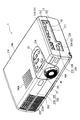
図1は、本発明に係るプロジェクタ1を上方前面側から見た斜視図である。図2は、プロジェクタ1を下方背面側から見た斜視図である。
図1または図2に示すように、プロジェクタ1は、射出成形によって成形された略直方体状の外装ケース2を備える。この外装ケース2は、光学像を形成する光学ユニット4(図3)と、プロジェクタ1の駆動制御を行う制御部を備えた図示しない制御基板および電源ユニットと、プロジェクタ1内の構成部品を冷却する冷却ユニット6とを収納する合成樹脂製の筐体であり、アッパーケース21と、ロアーケース22とを備え、これらのケース21,22は、互いに着脱自在に構成されている。
[1. First Embodiment]
DESCRIPTION OF EXEMPLARY EMBODIMENTS Hereinafter, a first embodiment of the invention will be described with reference to the drawings.
(1) Main Configuration of Projector FIG. 1 is a perspective view of a
As shown in FIG. 1 or FIG. 2, the
アッパーケース21は、図1および図2に示すように、プロジェクタ1の上面、側面、前面、および背面をそれぞれ構成する上面部21A、側面部21B、前面部21Cおよび背面部21Dを含んで構成される。
同様に、ロアーケース22も、プロジェクタ1の下面、側面、前面、および背面をそれぞれ構成する下面部22A、側面部22B、前面部22C、および背面部22Dを含んで構成される。
As shown in FIGS. 1 and 2, the
Similarly, the
従って、直方体状の外装ケース2において、アッパーケース21およびロアーケース22の側面部21B,22B同士が連続的に接続されて直方体の側面部分210が構成され、同様に、前面部21C,22C同士の接続で前面部分220が、背面部21D,22D同士の接続で背面部分230が、上面部21Aにより上面部分240が、下面部22Aにより下面部分250がそれぞれ構成される。
Therefore, in the rectangular parallelepiped
図1に示すように、上面部分240において、その前方側には操作パネル23が設けられ、この操作パネル23の近傍には音声出力用のスピーカ孔240Aが形成されている。このうち、操作パネル23には、プロジェクタ1を起動・調整操作を実施する各種スイッチが配設されている。これらスイッチとして、後述する冷却ユニット6の冷却媒体交換処理を実施する冷却媒体交換スイッチ23Aが設けられている。
As shown in FIG. 1, an
前方から見て右側の側面部分210には、2つの側面部21B,22Bを跨る開口211が形成されている。ここで、外装ケース2内には、プロジェクタ1の動作を制御する図示しない制御基板と、インターフェース基板52とが設けられており、この開口211に取り付けられるインターフェースパネル53を介して、制御基板に実装された接続部51Bと、インターフェース基板52に実装された接続部52Aとが外部に露出している。これらの接続部51B,52Aにおいて、プロジェクタ1には外部の電子機器等が接続される。
The right
前面部分220において、前方から見て右側で、前記操作パネル23の近傍には、2つの前面部21C,22Cを跨ぐ円形状の開口221が形成されている。この開口221に対応するように、外装ケース2内部には、投写レンズ46が配置されている。この際、開口221から投写レンズ46の先端部分が外部に露出しており、この露出部分の一部であるレバー46Aを介して、投写レンズ46のフォーカス操作が手動で行えるようになっている。
In the
前面部分220において、前記開口221の反対側の位置には、排気口222が形成されている。この排気口222には、安全カバー222Aが形成されている。
An
図2に示すように、背面部分230において、背面から見た右側には矩形状の開口部231が形成され、この開口部231からインレットコネクタ24が露出するようになっている。
また、背面部分230の略中央には、2つの略円形の開口部232,233と、これら開口部232,233に挟まれて略矩形の開口部234が形成されている。これら開口部232〜234には、後述する冷却媒体交換用カートリッジ7(図4および図6)が接続される。この開口部234内部には、カートリッジ7が接続されたか否かを検出するカートリッジ検出センサ2341(図7)が設けられている。このカートリッジ検出センサ2341は、制御部67(図7)に接続されており、カートリッジ7が接続されると、接続を示す電気信号が制御部67に出力されるように構成されている。
As shown in FIG. 2, in the
Further, two substantially
下面部分250において、下方から見て右端側の中央位置には矩形状の開口251が形成されている。開口251には、この開口251を覆うランプカバー25が着脱自在に設けられている。このランプカバー25を取り外すことにより、図示しない光源ランプの交換が容易に行えるようになっている。
In the
また、下面部分250において、下方から見て左側で背面側の隅部には、一段内側に凹んだ矩形面252が形成されている。この矩形面252には、外部から冷却空気を吸入するための吸気口252Aが形成されている。矩形面252には、この矩形面252を覆う吸気口カバー26が着脱自在に設けられている。吸気口カバー26には、吸気口252Aに対応する開口26Aが形成されている。開口26Aには、図示しないエアフィルタが設けられており、内部への塵埃の侵入が防止されている。
Further, in the
さらに、下面部分250において、後方側の略中央位置にはプロジェクタ1の脚部を構成する後脚2Rが形成されている。また、下面部22Aにおける前方側の左右の隅部には、同じくプロジェクタ1の脚部を構成する前脚2Fがそれぞれ設けられている。つまり、プロジェクタ1は、後脚2Rおよび2つ前脚2Fにより3点で支持されている。
2つの前脚2Fは、それぞれ上下方向に進退可能に構成されており、プロジェクタ1の前後方向および左右方向の傾き(姿勢)を調整して、投写画像の位置調整ができるようになっている。
Further, in the
Each of the two
また、図1,2に示すように、下面部分250と前面部分220とを跨るように、外装ケース2における前方側の略中央位置には、直方体状の凹部253が形成されている。この凹部253には、該凹部253の下側および前側を覆う前後方向にスライド自在なカバー部材27が設けられている。このカバー部材27により、凹部253には、プロジェクタ1の遠隔操作を行うための図示しないリモートコントローラ(リモコン)が収納される。
As shown in FIGS. 1 and 2, a
(2)光学ユニットの構造
図3は、光学ユニット4の構成を示す模式図である。
光学ユニット4は、前述の外装ケース2内に収納され、図3に示すように、光源装置411を構成する光源ランプ416から射出された光束を光学的に処理して画像情報に対応した光学像を形成し、この光学像を拡大して投射するユニットである。
この光学ユニット4は、インテグレータ照明光学系41と、色分離光学系42と、リレー光学系43と、プリズムユニット44と、投写レンズ46と、これらの光学部品41〜44,46を収納する図示しない光学部品用筐体とを備える。
(2) Structure of Optical Unit FIG. 3 is a schematic diagram showing the configuration of the optical unit 4.
The optical unit 4 is housed in the aforementioned
The optical unit 4 houses an integrator illumination
インテグレータ照明光学系41は、プリズムユニット44を構成する3枚の液晶パネル441(赤、緑、青の色光毎にそれぞれ液晶パネル441R,441G,441Bとする)の画像形成領域をほぼ均一に照明するための光学系であり、光源装置411と、第1レンズアレイ412と、第2レンズアレイ413と、偏光変換素子414と、重畳レンズ415とを備える。
The integrator illumination
光源装置411は、放射光源としての光源ランプ416と、リフレクタ417とを備え、光源ランプ416から射出された放射状の光線をリフレクタ417で反射して平行光線とし、この平行光線を外部へと射出する。光源ランプ416には、高圧水銀ランプを採用している。なお、高圧水銀ランプ以外に、メタルハライドランプやハロゲンランプ等も採用できる。また、リフレクタ417には、放物面鏡を採用している。なお、放物面鏡の代わりに、平行化凹レンズおよび楕円面鏡を組み合わせたものを採用してもよい。
The
第1レンズアレイ412は、光軸方向から見てほぼ矩形状の輪郭を有する小レンズがマトリクス状に配列された構成を有している。各小レンズは、光源ランプ416から射出される光束を、複数の部分光束に分割している。各小レンズの輪郭形状は、液晶パネル441の画像形成領域の形状とほぼ相似形をなすように設定されている。
The
第2レンズアレイ413は、第1レンズアレイ412と略同様な構成を有しており、小レンズがマトリクス状に配列された構成を有している。この第2レンズアレイ413は、重畳レンズ415とともに、第1レンズアレイ412の各小レンズの像を液晶パネル441上に結像させる機能を有する。
The
偏光変換素子414は、第2レンズアレイ413と重畳レンズ415との間に配置される。このような偏光変換素子414は、第2レンズアレイ413からの光を1種類の偏光光に変換するものであり、これにより、プリズムユニット44での光の利用効率が高められている。
The
具体的に、偏光変換素子414によって1種類の偏光光に変換された各部分光は、重畳レンズ415によって最終的にプリズムユニット44の液晶パネル441上にほぼ重畳される。偏光光を変調するタイプの液晶パネル441を用いたプロジェクタ1では、1種類の偏光光しか利用できないため、他種類のランダムな偏光光を発する光源ランプ416からの光束の略半分が利用されない。このため、偏光変換素子414を用いることにより、光源ランプ416から射出された光束を全て1種類の偏光光に変換し、プリズムユニット44での光の利用効率を高めている。なお、このような偏光変換素子414は、たとえば特開平8−304739号公報に紹介されている。
Specifically, each partial light converted into one type of polarized light by the
色分離光学系42は、2枚のダイクロイックミラー421,422と、反射ミラー423とを備え、ダイクロイックミラー421,422によりインテグレータ照明光学系41から射出された複数の部分光束を赤(R)、緑(G)、青(B)の3色の色光に分離する機能を有している。
The color separation
リレー光学系43は、入射側レンズ431と、リレーレンズ433と、反射ミラー432、434とを備え、色分離光学系42で分離された色光である赤色光を液晶パネル441Rまで導く機能を有している。
The relay
この際、色分離光学系42のダイクロイックミラー421では、インテグレータ照明光学系41から射出された光束のうち、赤色光成分と緑色光成分とは透過し、青色光成分は反射する。ダイクロイックミラー421によって反射した青色光は、反射ミラー423で反射し、フィールドレンズ418を通って、青色用の液晶パネル441Bに到達する。このフィールドレンズ418は、第2レンズアレイ413から射出された各部分光束をその中心軸(主光線)に対して平行な光束に変換する。他の液晶パネル441G,441Rの光入射側に設けられたフィールドレンズ418も同様である。
At this time, the
また、ダイクロイックミラー421を透過した赤色光と緑色光のうちで、緑色光は、ダイクロイックミラー422によって反射し、フィールドレンズ418を通って、緑色用の液晶パネル441Gに到達する。一方、赤色光は、ダイクロイックミラー422を透過してリレー光学系43を通り、さらにフィールドレンズ418を通って、赤色光用の液晶パネル441Rに到達する。
なお、赤色光にリレー光学系43が用いられているのは、赤色光の光路の長さが他の色光の光路長さよりも長いため、光の発散等による光の利用効率の低下を防止するためである。すなわち、入射側レンズ431に入射した部分光束をそのまま、フィールドレンズ418に伝えるためである。なお、リレー光学系43には、3つの色光のうちの赤色光を通す構成としたが、これに限らず、例えば、青色光を通す構成としてもよい。
Of the red light and green light transmitted through the
The relay
プリズムユニット44は、入射された光束を画像情報に応じて変調してカラー画像を形成するものであり、色分離光学系42で分離された各色光が入射される3つの入射側偏光板442と、各入射側偏光板442の後段に配置される光変調装置としての液晶パネル441R,441G,441Bと、各液晶パネル441R,441G,441Bの後段に配置される射出側偏光板443と、色合成光学系としてのクロスダイクロイックプリズム444とを備える。
The prism unit 44 modulates an incident light beam according to image information to form a color image. The prism unit 44 includes three incident-side
液晶パネル441R,441G,441Bは、例えば、ポリシリコンTFTをスイッチング素子として用いたものである。
プリズムユニット44において、色分離光学系42で分離された各色光は、これら3枚の液晶パネル441R,441G,441B、入射側偏光板442、および射出側偏光板443によって画像情報に応じて変調されて光学像を形成する。
The liquid crystal panels 441R, 441G, and 441B use, for example, polysilicon TFTs as switching elements.
In the prism unit 44, the respective color lights separated by the color separation
入射側偏光板442は、色分離光学系42で分離された各色光のうち、一定方向の偏光光のみ透過させ、その他の光束を吸収するものであり、サファイアガラス等の基板に偏光膜が貼付されたものである。また、基板を用いずに、偏光膜をフィールドレンズ418に貼り付けてもよい。
射出側偏光板443も、入射側偏光板442と略同様に構成され、液晶パネル441(441R,441G,441B)から射出された光束のうち、所定方向の偏光光のみ透過させ、その他の光束を吸収するものである。また、基板を用いずに、偏光膜をクロスダイクロイックプリズム444に貼り付けてもよい。
これらの入射側偏光板442および射出側偏光板443は、互いの偏光軸の方向が直交するように設定されている。
The incident
The exit-side
The incident
クロスダイクロイックプリズム444は、射出側偏光板443から射出され、各色光毎に変調された光学像を合成してカラー画像を形成するものである。
クロスダイクロイックプリズム444には、赤色光を反射する誘電体多層膜と青色光を反射する誘電体多層膜とが、4つの直角プリズムの界面に沿って略X字状に設けられ、これらの誘電体多層膜により3つの色光が合成される。このようなクロスダイクロイックプリズム444は光学ガラスにより構成されている。
投写レンズ46は、プリズムユニット44のクロスダイクロイックプリズム444で合成されたカラー画像を拡大して投写するものである。
The cross
The cross
The
(3)冷却ユニットの構造
図4は、プロジェクタ1内に配置された冷却ユニット6と、この冷却ユニット6に接続される冷却媒体交換用カートリッジ7を模式的に示した図である。
冷却ユニット6は、外装ケース2内に設けられ、エチレングリコール溶液等の液状の冷却媒体を循環させて、プロジェクタ1内に配置された冷却を要する部品を冷却媒体により冷却する冷却系である。
冷却ユニット6は、前述の光学ユニット4に設けられた素子としての液晶パネル441および射出側偏光板443を冷却する冷却装置61と、冷却媒体を一時的に貯蔵する冷却媒体貯蔵部としてのタンク62と、冷却装置61およびタンク62間に冷却媒体を循環させる媒体循環装置としてのポンプ63と、これら冷却装置61、タンク62およびポンプ63を接続し、冷却媒体流通経路を形成する配管64とを備える。
このうち、配管64は、タンク62から冷却装置61に冷却媒体を導く第1配管641と、冷却装置61での冷却に供された冷却媒体をタンク62に戻す第2配管642とから構成されている。
(3) Structure of Cooling Unit FIG. 4 is a diagram schematically showing the cooling unit 6 disposed in the
The cooling unit 6 is a cooling system that is provided in the
The cooling unit 6 includes a
Among these, the
冷却装置61は、前述のように、液晶パネル441および射出側偏光板443で発生した熱を冷却媒体によって冷却するものである。
この冷却装置61は、第1配管641に接続され、ポンプ63から圧送される冷却媒体を中継する中継部材611と、この中継部材611から送られる冷却媒体により、液晶パネル441および射出側偏光板443を冷却する冷却部材612と、これら中継部材611および冷却部材612間を接続する配管613とを備えている。
このうち、配管613は、中継部材611から冷却部材612に冷却媒体を送り出す往路側配管613Aと、冷却部材612での冷却に供された冷却媒体を中継部材611に戻す復路側配管613Bとから構成されている。
As described above, the
The
Among these, the
中継部材611は、詳しい図示を省略するが、アルミニウム製の中空部材であり、第1配管641を介してタンク62から送出される冷却媒体を冷却部材612に送るとともに、冷却部材612での冷却に供された冷却媒体を回収して第2配管642に送出する部材である。この中継部材611は、前述のクロスダイクロイックプリズム444に載置されている。
Although not shown in detail, the
冷却部材612は、クロスダイクロイックプリズム444の各光束入射面に配置される液晶パネル441および射出側偏光板443(図3)と熱伝導可能に接触するとともに、これら液晶パネル441および射出側偏光板443で発生した熱を、中継部材611から送られる冷却媒体によって冷却する部材である。
この冷却部材612内部には、中継部材611から往路側配管613Aを介して送られる冷却媒体が流通し、この冷却媒体は、液晶パネル441および射出側偏光板443を冷却した後、復路側配管613Bを介して中継部材611に送られる。
The cooling
Inside the cooling
図5は、タンク62の上下方向の断面図である。
タンク62は、冷却媒体を一時的に貯蔵する。このタンク62には、タンク62内が冷却媒体で満たされているか否かを検出する満量検出部としての満量検出センサ621(図5では図示省略、図7参照)が設けられている。この満量検出センサ621は、制御部67に接続されており、満量検出センサ621による検出結果は、制御部67に送信される。
このタンク62の上面には、図5に示すように、ポンプ63から圧送される冷却媒体が流通する第2配管642が接続され、タンク62の底面には、冷却装置61にタンク62内の冷却媒体を送出する第1配管641が接続されている。このため、第2配管642を介してポンプ63から圧送される冷却媒体は、図5中矢印A31方向、すなわちタンク62上方からタンク62内に流入し、第1配管641を介して矢印A4方向、すなわちタンク62底部から送出される。
このようなタンク62を設けることにより、冷却ユニット6を流通するのに必要な量の冷却媒体より多くの冷却媒体を確保することができ、冷却ユニット6内を流通する冷却媒体の安定した供給を維持できる。また、このタンク62内においては、冷却装置61での冷却に供され、熱せられた冷却媒体が自然放熱されるので、冷却ユニット6による冷却効率を向上できる。
FIG. 5 is a vertical sectional view of the
The
As shown in FIG. 5, a
By providing such a
ポンプ63は、配管64内に冷却媒体を圧送するもので、制御部67によって駆動が制御されている。このポンプ63は、詳しい図示を省略するが、例えば、略直方体状のアルミニウム製の中空部材内に羽車が配置された構成を有している。このようなポンプ63により、タンク62および配管64内の冷却媒体を強制的に循環させる。
The
配管64は、内部に冷却媒体が流通可能にアルミニウム製の管状部材で形成され、前述のように、第1配管641および第2配管642により構成されている。なお、配管64は、アルミニウム以外に、ステンレス等の金属や、合成樹脂製またはゴムパイプ等により形成してもよい。なお、金属製の管状部材とすれば、流通する冷却媒体の放熱が、これら配管64の流通中にも行われるので、冷却媒体による冷却効率を一層向上できる。
このうち、冷却装置61およびタンク62間を接続し、タンク62から冷却媒体を冷却装置61に導く第1配管641の流路には、フィルタ65が介装されている。
フィルタ65は、流通する冷却媒体の不純物を濾し取るためのメッシュ状のフィルタである。このフィルタ65は、交換可能に装着されており、外装ケース2の図示しない開口から取り外すことができる。
The
Among these, the
The
冷却装置61およびタンク62間を接続し、冷却装置61での冷却に供された冷却媒体がタンク62に戻る第2配管642の流路には、ポンプ63のほかに、熱を帯びた冷却媒体を冷却するラジエータ66が介装されている。
ラジエータ66内には、詳しい図示を省略するが、第2配管642に接続される略S字状のアルミニウム製の管状部材と、この管状部材に熱伝導可能に接触する放熱フィンと、この放熱フィンに取り付けられる冷却ファンとが設けられている。この管状部材内を流通する冷却媒体の熱は、放熱フィンに伝導された後、冷却ファンから送風される冷却空気によって冷却される。これにより、冷却ユニット6を流通する冷却媒体を低温に保つことができる。
The cooling
Although not shown in detail in the
また、第2配管642には、2つのT字管6411,6421が設けられている。これらT字管6411,6421のうち、ポンプ63からの冷却媒体圧送方向の下流側、すなわち、タンク62に近接する側に、T字管6411が設けられ、冷却媒体圧送方向の上流側、すなわち、ポンプ63に近接する側に、T字管6421が設けられている。
T字管6411に形成された3つの枝管のうち、2つは第2配管642に接続され、もう1つの枝管は、前述の外装ケース2に形成された開口部232に露出する継手6412に接続されている。この継手6412は、冷却媒体の交換時に、新たな冷却媒体を供給するための供給用継手である。
同様に、T字管6421に形成された3つの枝管のうち、2つは第2配管642に接続され、もう1つの枝管は、開口部233に露出する継手6422に接続されている。この継手6422は、冷却媒体の交換時に、冷却ユニット6内を流通していた冷却媒体を排出するための排出用継手である。この排出用継手6422には、この排出用継手6422を流通する冷却媒体の液量を検出する液量検出部としての液量検出センサ6422B(図7)が設けられている。この液量検出センサ6422Bは、制御部67に電気的に接続されており、液量検出センサ6422Bによる検出結果は、制御部67に出力される。
The
Of the three branch pipes formed in the T-shaped
Similarly, two of the three branch pipes formed in the T-shaped
供給用継手6412および排出用継手6422には、冷却媒体交換用のカートリッジ7が接続される。これら供給用継手6412および排出用継手6422には、カートリッジ7のロック機構6412A,6422A(図7)が設けられており、冷却媒体の交換中には、カートリッジ7が取り外せないようになっている。これらロック機構6412A,6422Aによるカートリッジ7のロック・アンロックは、制御部67から出力される電気信号に基づいて行われる。
なお、供給用継手6412および排出用継手6422は、カートリッジ7が接続された場合にのみ、冷却媒体の流通が可能となるように、カプラ等により構成されている。
A cooling medium replacement cartridge 7 is connected to the supply joint 6412 and the discharge joint 6422. The supply joint 6412 and the discharge joint 6422 are provided with
The supply joint 6412 and the discharge joint 6422 are configured by a coupler or the like so that the coolant can be circulated only when the cartridge 7 is connected.
さらに、第2配管642におけるT字管6411およびT字管6421の間には、第2配管642内の冷却媒体の流通経路を切り替える流路切替部としてのバルブ643が設けられている。このバルブ643は制御部67に接続されており、この制御部67によって、バルブ643の開放および閉塞が制御され、第2配管642における冷却媒体の流路が切り替えられる。
Furthermore, a
このような冷却ユニット6により、冷却媒体は以下のように循環する。
すなわち、通常の状態では、ポンプ63から第2配管642内に圧送された冷却媒体は、図4中矢印A1方向に流通して、T字管6421に到達する。ここで、カートリッジ7が接続されていない場合は、排出用継手6422および供給用継手6412は閉状態とされ、また、バルブ643は、開放されているので、冷却媒体は、矢印A2,A3方向に流通し、タンク62に向かって流通する。
タンク62に向かって流通した冷却媒体は、図5中矢印A31で示すように、タンク62上部からタンク62内に流入した後、タンク62底部から図4および図5中矢印A4方向に送出され、第1配管641内を流通して冷却装置61に到達する。
冷却装置61に到達した冷却媒体は、中継部材611から往路側配管613Aを介して冷却部材612に送出され、液晶パネル441および射出側偏光板443を冷却した後、復路側配管613Bを介して、再び中継部材611に戻り、第2配管642内を矢印A5方向に流通する。この冷却媒体は、ラジエータ66で冷却された後、再び、ポンプ63に戻る。
このように、冷却ユニット6は、冷却媒体を循環させ、この循環経路中に設けられた冷却装置61によって、液晶パネル441および射出側偏光板443を冷却している。
With such a cooling unit 6, the cooling medium circulates as follows.
That is, in a normal state, the cooling medium pumped from the
As shown by an arrow A31 in FIG. 5, the cooling medium flowing toward the
The cooling medium that has reached the
Thus, the cooling unit 6 circulates the cooling medium, and cools the liquid crystal panel 441 and the emission-side
図6は、開口部232,233を介して供給用継手6412および排出用継手6422に接続される冷却媒体交換用カートリッジ7の概要斜視図である。
カートリッジ7は、冷却媒体の交換時に、冷却ユニット6を流通する冷却媒体が排出用継手6422を介して排出されるとともに、供給用継手6412を介して新たな冷却媒体を供給するものである。
このカートリッジ7は、図4および図6に示すように、2つのタンク71,72と、カートリッジ7から露出する接続部73と、この接続部73およびタンク71,72を接続する配管74,75と、これら配管74,75の流路を切り替える切替部76と、この切替部76による流路切替を制御する制御部77とを備えている。
FIG. 6 is a schematic perspective view of the cooling medium replacement cartridge 7 connected to the supply joint 6412 and the discharge joint 6422 through the
In the cartridge 7, when the cooling medium is replaced, the cooling medium flowing through the cooling unit 6 is discharged through the discharge joint 6422 and a new cooling medium is supplied through the
As shown in FIGS. 4 and 6, the cartridge 7 includes two
タンク71,72は、カートリッジ7内に収納された、略直方体形状を有した合成樹脂製の中空部材である。このうち、タンク71は、第2貯留部に相当し、冷却媒体の交換時に、プロジェクタ1内の冷却ユニット6に供給する新たな冷却媒体を貯留しておくための供給用タンクである。また、タンク72は、第1貯留部に相当し、冷却ユニット6を流通する冷却媒体が排出される排出用タンクである。
供給用タンク71には2つの開口部が形成されている。具体的には、排出用タンク72に対向する供給用タンク71の側面とは反対側の側面下方には、開口部712が形成され、また、供給用タンク71の上面には、開口部711が形成されている。
同様に、排出用タンク72にも2つの開口部が形成されている。具体的には、供給用タンク71の底面には、開口部721が形成され、また、排出用タンク72の上面には、開口部722が形成されている。
The
Two openings are formed in the
Similarly, two openings are formed in the
接続部73は、カートリッジ7外部に露出し、前述の供給用継手6412に接続される第1接続部731と、排出用継手6422に接続される第2接続部732から構成されている。
The
配管74は、第1接続部731と、供給用タンク71および排出用タンク72とを接続するアルミニウム製の管状部材である。この配管74は、T字管741と、第1供給用配管742と、第2供給用配管743とを備えている。
このうち、T字管741に形成された3つの枝管のうち、1つは第1接続部731に、1つは第1供給用配管742に、もう1つは第2供給用配管743にそれぞれ接続される。第1供給用配管742は、一端がT字管741に接続され、他端が供給用タンク71の底面に形成された開口部712に接続される。また、第2供給用配管743は、同様に、一端がT字管741に接続され、他端が排出用タンク72の開口部722に接続される。
The
Of these, one of the three branch pipes formed on the T-shaped
配管75は、配管74と同様の構成を備え、第2接続部732と、供給用タンク71および排出用タンク72とを接続する。
すなわち、配管75は、T字管751と、第1排出用配管752と、第2排出用配管753とを備えている。このT字管751に構成された3つの枝管のうち、1つは、第2接続部732と接続され、別の1つは、排出用タンク72の開口部721と接続される第1排出用配管752と接続され、さらに別の1つは、供給用タンクの開口部711に接続される第2排出用配管753と接続される。
なお、配管74,75は、アルミニウム以外の金属、合成樹脂およびゴム等により構成してもよい。
The
That is, the
The
切替部76は、前述のように、配管74,75内の流通経路を切り替えるものであり、配管74,75にそれぞれ2つずつ設けられたバルブ761,762,763,764から構成されている。このうち、バルブ761は、配管74を構成する第1供給用配管742に設けられ、バルブ762は、第2供給用配管743に設けられている。また、バルブ763は、配管75を構成する第1排出用配管752に設けられ、バルブ764は、第2排出用配管753に設けられている。
この切替部76は、制御部77と電気的に接続され、制御部77からの電気信号に基づいて、各バルブ761〜764の開放および閉塞の切替が制御される。
As described above, the switching
The switching
制御部77は、プロジェクタ1の冷却ユニット6を制御する制御部67(図7)と電気的に接続され、制御部67から出力されるバルブ開閉信号を受けて、切替部76の各バルブ761〜764の開放および閉塞の切替制御を行う。また、この制御部77には、メモリ772(図7)が組み込まれており、冷却媒体の交換時に、このメモリ772の読み書きが行われる。すなわち、メモリ772には、カートリッジ7が未使用状態の場合、未使用である旨のデータが書き込まれており、冷却媒体の交換が行われた後には、このメモリ772は、使用済である旨のデータで上書きされる。なお、このメモリ772は、未使用および使用済の状態を区別できるスイッチ等により構成してもよい。
また、制御部77は、カートリッジ7外部に露出し、制御部67に接続される端子771を備えている。この端子771は、プロジェクタ1の外装ケース2に形成された開口部234に挿入され、この開口部234内に配置された図示しないコネクタに接続される。このコネクタは、制御部67に接続されており、これにより、制御部67および制御部77が、コネクタおよび端子771を介して接続される。
The
The
このような冷却媒体交換用カートリッジ7によれば、供給用タンク71および排出用タンク72が、1つのカートリッジ7内に設けられ、また、これら供給用タンク71から供給される新たな冷却媒体の流路、および、排出用タンク72へ排出される冷却媒体の流路がそれぞれ別の接続部731,732に接続されるので、供給および排出のうちの一方の処理により流路の占有がされず、冷却媒体の円滑な流通を図ることができる。
また、このような1つのカートリッジ7に供給用タンク71および排出用タンク72が設けられているので、このカートリッジ7をプロジェクタ1に装着することにより、冷却媒体の交換を行うことができる。従って、冷却媒体の交換を容易に行うことができる。
According to such a cooling medium replacement cartridge 7, the
Further, since the
図7は、冷却媒体交換時の動作を制御する制御部67の構成を示すブロック図である。
制御部67は、冷却ユニット6の冷却動作を制御する制御装置として、プロジェクタ1の動作を制御する図示しない制御基板に設けられている。
この制御部67は、媒体交換制御部671と、ポンプ駆動制御部672と、バルブ開閉制御部673と、ロック機構制御部674とを備えている。また、この制御部67は、開口部234内部に配置された図示しないコネクタおよびカートリッジ7に設けられた端子771を介して制御部77に接続される。
FIG. 7 is a block diagram showing the configuration of the
The
The
媒体交換制御部671は、前述の冷却媒体交換スイッチ23A、カートリッジ検出センサ2341、液量検出センサ6422Bおよび満量検出センサ621と接続され、これらスイッチ23Aおよびセンサ2341,6422B,621から出力される電気信号を受けて、冷却媒体交換時に、ポンプ63の駆動信号、バルブ643の開閉信号、ロック機構6412A,6422Aのロック・アンロック信号およびカートリッジ7のバルブ761〜764の開閉信号を、ポンプ駆動制御部672、バルブ開閉制御部673、ロック機構制御部674、および前述のカートリッジ7の制御部77にそれぞれ出力する。
ポンプ駆動制御部672は、媒体交換制御部671からのポンプ駆動信号に基づいてポンプ63の駆動を制御する。
バルブ開閉制御部673は、媒体交換制御部671からのバルブ開閉信号に基づいてバルブ643の開閉制御を行い、第2配管642における冷却媒体の流通経路を切り替える。
ロック機構制御部674は、媒体交換制御部671からのロック・アンロック信号に基づいて、ロック機構6412A,6422Aにおけるカートリッジ7のロックおよびアンロックの切替制御を行う。
The medium
The pump
The valve opening /
Based on the lock / unlock signal from the medium
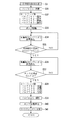
(4)冷却媒体の交換処理
図8は、冷却媒体交換時の処理手順を示すフローチャートである。また、図9は、冷却媒体交換時に行われる冷却媒体排出処理の手順を示すフローチャートであり、図10は、同じく冷却媒体交換時の冷却媒体供給処理の手順を示すフローチャートである。
以下に、冷却ユニット6および冷却媒体交換用カートリッジ7の冷却媒体交換処理の手順について、図8〜図10に基づいて説明する。
(4) Cooling Medium Replacement Process FIG. 8 is a flowchart showing a processing procedure when the cooling medium is replaced. FIG. 9 is a flowchart showing the procedure of the cooling medium discharge process performed when the cooling medium is replaced. FIG. 10 is a flowchart showing the procedure of the cooling medium supply process when the cooling medium is replaced.
Below, the procedure of the cooling medium replacement process of the cooling unit 6 and the cooling medium replacement cartridge 7 will be described with reference to FIGS.
冷却媒体交換処理は、前述の冷却媒体交換スイッチ23Aの入力による電気信号が、媒体交換制御部671に入力されることによって開始される。この際、冷却媒体の交換中である旨のメッセージを表示させてもよく、図示しないスピーカを介して同趣旨の音声を出力してもよい。
冷却媒体交換処理(処理S1)では、図8に示すように、はじめに、カートリッジ検出センサ2341によって、カートリッジ7の検出が行われる(処理S11)。この後、カートリッジ検出センサ2341での検出結果を、媒体交換制御部671が判定(処理S12)して、カートリッジ7が装着されていない場合には、冷却媒体交換処理を終了させる。この際、カートリッジ7が装着されていない旨のメッセージを投写画像として表示させてもよく、音声として出力してもよい。
The cooling medium replacement process is started when an electric signal input from the above-described cooling
In the cooling medium replacement process (process S1), as shown in FIG. 8, first, the cartridge 7 is detected by the cartridge detection sensor 2341 (process S11). Thereafter, the medium
カートリッジ7が装着されている場合は、冷却媒体の交換中にカートリッジ7が脱落したり、使用者によって取り外されたりして、冷却媒体が排出用継手6422から漏出しないように、カートリッジ7をロックする(処理S13)。この処理は、媒体交換制御部671から出力されるロック信号に基づいて、ロック機構制御部674が、ロック機構6412A,6422Aを稼動させて、カートリッジ7をロック状態とすることによって行われる。
When the cartridge 7 is mounted, the cartridge 7 is locked so that the cooling medium is not dropped during the replacement of the cooling medium or is removed by the user so that the cooling medium does not leak from the discharge joint 6422. (Process S13). This process is performed by the lock
次に、カートリッジ7の制御部77のメモリ772上に記録されたデータ(情報)の取得を行う(処理S14)。制御部77は、メモリ772上のデータを取得して、端子771を介して、媒体交換制御部671に出力し、媒体交換制御部671では、出力されたデータの判定を行う(処理S15)。この処理では、接続されたカートリッジ7が未使用であるか、使用済みでないかが判定される。カートリッジ7が使用済みである場合は、カートリッジ7のロックを解除(処理S17)して、冷却媒体交換処理が終了する。この際、カートリッジ7が使用済みである旨のメッセージを画像および/または音声として出力してもよい。また、カートリッジ7が未使用である場合は、冷却媒体を排出する冷却媒体排出処理(処理S2)を行う。
Next, data (information) recorded on the
冷却媒体排出処理(処理S2)では、図9に示すように、はじめに冷却ユニット6のバルブ643の切替制御(処理S21)を行う。この処理では、媒体交換制御部671の開閉信号を元に、バルブ開閉制御部673がバルブ643を閉塞する。
次に、カートリッジ7のバルブ761〜764の切替制御(処理S22)を行う。この処理では、媒体交換制御部671から出力される電気信号に基づいて、カートリッジ7の制御部77が、全て閉塞していたバルブ761〜764のうち、バルブ761,764を閉塞し、バルブ762,763を開放する。この状態で、ポンプ駆動制御部672を介して、ポンプ63を駆動させる(処理S23)。
In the cooling medium discharge process (process S2), as shown in FIG. 9, first, switching control (process S21) of the
Next, switching control (processing S22) of the
これにより、図4に示すように、バルブ643が閉塞されるので、T字管6421における冷却媒体の流通方向が矢印B1方向となり、さらに、カートリッジ7の配管75のT字管751における流通方向が矢印C1方向となるので、冷却ユニット6を流通する冷却媒体は、排出用継手6422を介して排出用タンク72内に排出される。また、カートリッジ7の配管74のT字管741における流通方向が矢印C3方向となり、さらに、第2配管642のT字管6411における流通方向が矢印B2方向となるので、排出用タンク72に貯留されていた空気が、供給用継手6412を介して、第2配管641内に供給される。
ここで、冷却媒体は、排出用タンク72の下方に形成された開口部721を介して排出され、排出用タンク72内に封入されていた空気は、排出用タンク72の上面に形成された開口部722から供給用継手6412に供給されるので、排出用タンク72内に排出された冷却媒体が、再び、供給用継手6412を介して第2配管641に供給されるのを防ぐことができる。
従って、冷却ユニット6の冷却媒体を排出できるとともに、冷却媒体の代わりに空気を供給することができるので、冷却ユニット6を構成する各部材内が減圧されることを防ぐことができ、減圧に起因する破損・損傷を防ぐことができる。
As a result, as shown in FIG. 4, the
Here, the cooling medium is discharged through an
Therefore, since the cooling medium of the cooling unit 6 can be discharged and air can be supplied instead of the cooling medium, the inside of each member constituting the cooling unit 6 can be prevented from being depressurized. Can prevent breakage and damage.
次に、図9に示すように、排出用継手6422に設けられた液量検出センサ6422Bにより、排出用継手6422を流通する冷却媒体の液量を検出する(処理S24)。この検出結果は、媒体交換制御部671に出力され、冷却媒体の液量が判定される(処理S25)。ここで、排出用継手6422を流通する冷却媒体が0でない場合は、冷却媒体の排出が継続されているとみなして、処理S24および処理S25を繰り返す。また、排出用継手6422を流通する冷却媒体が0の場合は、冷却媒体の排出が完了したとみなして、媒体交換制御部671は、ポンプ駆動制御部672を介して、ポンプ63の駆動を停止させる。また、ここで、タンク62の第1配管641との接続部分は、タンク62底面に形成されているので、タンク62内の冷却媒体の略全てが流出しない限り、排出用継手6422における液量が0とはならない。また、この排出用継手6422における液量が0である場合は、冷却ユニット6内の冷却媒体が略全てが排出されたとみなすことができる。これにより、冷却媒体の排出の完了を検出できるので、確実に冷却媒体の排出を行うことができ、また、迅速に新たな冷却媒体の供給処理を行うことができる。
Next, as shown in FIG. 9, the liquid amount of the cooling medium flowing through the discharge joint 6422 is detected by the liquid amount detection sensor 6422B provided in the discharge joint 6422 (process S24). The detection result is output to the medium
冷却媒体の排出が終了した後、図8に示すように、カートリッジ7から新たな冷却媒体を冷却ユニット6に供給する冷却媒体供給処理(処理S3)を行う。
冷却媒体供給処理(処理S3)では、図10に示すように、はじめに、媒体交換制御部671は、バルブ開閉制御部673を介して、第2配管642に設けられたバルブ643を閉塞する(処理S31)。通常は、この処理S31を実施しなくても、冷却媒体交換時には、前述の処理S21によりバルブ643は閉塞されている。
この後、媒体交換制御部671は、カートリッジ7の制御部77を介して、バルブ761,764を開放し、バルブ762,763を閉塞する(処理S32)。この状態で、媒体交換制御部671は、ポンプ駆動制御部672を介してポンプ63を駆動させる(処理S33)。
After the discharge of the cooling medium is completed, as shown in FIG. 8, a cooling medium supply process (process S3) for supplying a new cooling medium from the cartridge 7 to the cooling unit 6 is performed.
In the cooling medium supply process (process S3), as shown in FIG. 10, first, the medium
Thereafter, the medium
これにより、図4に示すように、カートリッジ7の配管74に設けられたT字管741における流通方向が矢印C4方向となり、また、第2配管642のT字管6411における流通方向が矢印B2方向となるので、供給用タンク71内の新たな冷却媒体は、図4中矢印C4,B2方向および図5中矢印A31方向に流通して、タンク62内に貯蔵される。また、図4に示すように、第2配管642のT字管6421では、新たな冷却媒体または前述の冷却媒体排出処理(処理S2)で供給された排出用タンク72の空気が、バルブ643が閉塞され、カートリッジ7のバルブ764が開放されることにより、矢印B1およびC2方向に流通して、供給用タンク71に戻る。
ここで、新たな冷却媒体は、供給用タンク71の底面に形成された開口部712から供給されるので、供給用タンク71内に貯蔵された新たな冷却媒体の略全てを利用することができる。また、これと合わせて、冷却媒体の代わりに冷却ユニット6を流通していた空気は、供給用タンク71の上面に形成された開口部711を介して、供給用タンク71に供給される。これにより、供給用タンク71から確実に、新たな冷却媒体を供給することができる。
従って、新たな冷却媒体の供給時に、冷却ユニット6を構成する各部材内が加圧されることを防ぐことができるので、前述の冷却媒体の排出時と同様に、各部材の破損・損傷を防ぐことができる。
As a result, as shown in FIG. 4, the flow direction in the T-shaped
Here, since the new cooling medium is supplied from the
Therefore, it is possible to prevent the inside of each member constituting the cooling unit 6 from being pressurized when a new cooling medium is supplied, so that each member is prevented from being damaged or damaged in the same manner as when the cooling medium is discharged. Can be prevented.
次に、図10に示すように、液量検出センサ6422Bによる排出用継手6422を流通する冷却媒体の流量を検出する(処理S34)。この検出結果は、媒体交換制御部671に出力され、この検出結果を基に冷却媒体の流量が判定され、冷却媒体の流通があるか否かが判定される(処理S35)。ここで、排出用継手6422における冷却媒体の流通が検出されない場合、すなわち、冷却媒体の流量が0の場合は、配管64内が新たな冷却媒体で充填されていないとしてみなして、新たな冷却媒体の供給を継続させるために、処理S34およびS35を繰り返す。また、冷却媒体の流通が検出された場合、すなわち、冷却媒体の流量が0以上の場合は、供給用配管6412から供給された新たな冷却媒体が、第2配管642の排出用継手6422まで到達したとみなして、次の処理に移行する。
Next, as shown in FIG. 10, the flow rate of the cooling medium flowing through the discharge joint 6422 by the liquid amount detection sensor 6422B is detected (processing S34). The detection result is output to the medium
次に、タンク62に設けられた満量検出センサ621により、タンク62内の冷却媒体の満量検出を行う(処理S36)。この検出結果は、媒体交換制御部671に出力され、タンク62が新たな冷却媒体で満量されたか否かが判定される(処理S37)。ここで、タンク62が満量されていない場合は、新たな冷却媒体の供給が完了していないとみなして、処理S36および処理S37を繰り返す。また、タンク62の満量が検出された場合は、媒体交換制御部671は、制御部77を介して、カートリッジ7のバルブ761〜764を全て閉塞させ(処理S38)、また、バルブ開閉制御部673を介して、冷却ユニット6のバルブ643を開放し(処理S39)、ポンプ63の駆動を停止させる(処理S40)。この後、カートリッジ7の制御部77に設けられたメモリ772を、使用済みを示すデータ(情報)に更新する(処理S41)。
なお、処理S34,S35と、処理S36,S37とは、順序が逆であってもよい。すなわち、先に処理S36,S37を実施した後、処理S34,S35を実施するようにしてもよい。
Next, the full amount detection of the cooling medium in the
Note that the order of the processes S34 and S35 and the processes S36 and S37 may be reversed. That is, the processes S34 and S35 may be performed after the processes S36 and S37 are performed first.
これにより、液量検出センサ6422Bにより、排出用継手6422における新たな冷却媒体の流通が検出され、また、満量検出センサ621により、タンク62内が新たな冷却媒体で満量されたことが検出されるので、冷却ユニット6内の冷却媒体が交換されたことを確認できる。従って、冷却媒体の供給処理を迅速に終了させることができる。また、メモリ772を、使用済みを示すデータ(情報)に更新することにより、使用済みカートリッジ7が再び装着された場合でも、交換処理を行わないようにすることができるとともに、使用済みである旨を使用者に知らせることができる。
Accordingly, the flow detection sensor 6422B detects the flow of a new cooling medium in the discharge joint 6422, and the full quantity detection sensor 621 detects that the
冷却媒体供給処理(処理S3)が終了した後、媒体交換制御部671は、再びポンプ63を駆動させて、冷却ユニット6における冷却媒体の循環に異常が無いことを確認する(処理S16)。ここで、冷却媒体の循環に異常が発生した場合には、その旨を示すメッセージを画像および/または音声として出力してもよい。この後、媒体交換制御部671は、ロック機構制御部674を介して、ロック機構6412A,6422Aをアンロックして、カートリッジ7の取り外しを可能にする(処理S17)。
以上で、冷却媒体の交換処理が終了する。
After the cooling medium supply process (process S3) is completed, the medium
This completes the cooling medium replacement process.
このような冷却媒体の交換処理は、カートリッジ7を取り付け、冷却媒体交換スイッチ23Aが入力された後は、媒体交換制御部671により自動で行うことができる。すなわち、ポンプ63、バルブ643、ロック機構6412A,6422Aおよびカートリッジ7のバルブ761〜764を、それぞれポンプ駆動制御部672、バルブ開閉制御部673、ロック機構制御部674およびカートリッジ7の制御部77を介して、媒体交換制御部671が制御することにより、冷却ユニット6内を循環していた冷却媒体と、冷却媒体交換用カートリッジ7の新たな冷却媒体とを交換することができる。従って、使用者の特別な操作を必要とせずに、簡単に冷却媒体の交換を行うことができる。
Such a cooling medium replacement process can be automatically performed by the medium
〔2.実施形態の変形〕
本発明は前述の実施形態に限定されるものではなく、本発明の目的を達成できる範囲での変形、改良等は本発明に含まれるものである。
例えば、前記実施形態では、新たな冷却媒体を供給する供給用継手6412と、冷却媒体を排出する排出用継手6422とを、それぞれ分けて設けたが、1つの継手で冷却媒体の排出および供給を行う構成としてもよい。この場合、空気は流通するが冷却媒体は流通しない開口を配管64に設ければ、冷却媒体の交換時に、冷却ユニット6内が減圧または加圧状態になることを防ぐことができる。なお、冷却ユニット6に供給用継手6412および排出用継手6422をそれぞれ設け、冷却媒体の排出時には、カートリッジ7の排出用タンク72に封入されていた空気を冷却ユニット6内に流通させ、新たな冷却媒体の供給時には、流通していた空気を、供給用タンク71内に流通させる構成とすれば、確実に、加減圧による冷却ユニット6の破損・損傷を抑えることができる。また、冷却媒体の漏出の危険性を低減することができるだけでなく、冷却媒体交換後の空気の混入を防ぐことができる。
[2. Modification of Embodiment]
The present invention is not limited to the above-described embodiment, and modifications, improvements, and the like within the scope that can achieve the object of the present invention are included in the present invention.
For example, in the above embodiment, the
前記実施形態では、供給用継手6412および排出用継手6422を第2配管642に設ける構成としたが、本発明はこれに限らず、供給用継手6412および排出用継手6422のそれぞれを、第1配管641に設ける構成としてもよい。また、供給用継手6412および排出用継手6422のいずれか一方を第1配管641に設け、他方を第2配管に設ける構成でもよい。すなわち、供給用継手6412および排出用継手6422の配置位置は問わない。
In the above embodiment, the supply joint 6412 and the discharge joint 6422 are provided in the
前記実施形態では、ポンプ63からの冷却媒体圧送方向の上流側に、排出用継手6422を設け、下流側に供給用継手6412を設ける構成としたが、それぞれの配置位置を逆にしてもよい。すなわち、上流側に供給用継手6412を設け、下流側に排出用継手6422を設ける構成としてもよい。なお、上流側に排出用継手6422を設け、下流側に供給用継手6412を設ける前記実施形態の構成とすれば、冷却媒体の排出時に、冷却媒体が排出される流路と、冷却媒体の代わりに流通する空気の流通経路とが重複せず、また、冷却媒体の供給時に、空気が流通する流路と、供給される新たな冷却媒体の流通経路とが重複しないため、円滑に冷却媒体の交換を行うことができる。
In the above-described embodiment, the discharge joint 6422 is provided on the upstream side in the cooling medium pumping direction from the
前記実施形態では、冷却媒体を排出した後に、新たな冷却媒体を供給する冷却媒体交換処理手順としたが、冷却媒体の排出と供給を同時に行う処理手順を採用してもよい。なお、冷却ユニット6を循環していた冷却媒体を排出した後に、新たな冷却媒体を供給する手順とすれば、使用済みの冷却媒体と、新たな冷却媒体とを確実に交換できる。 In the embodiment, the cooling medium replacement processing procedure for supplying a new cooling medium after discharging the cooling medium is used. However, a processing procedure for simultaneously discharging and supplying the cooling medium may be adopted. In addition, if it is set as the procedure which supplies a new cooling medium after discharging | emitting the cooling medium which circulated through the cooling unit 6, a used cooling medium and a new cooling medium can be exchanged reliably.
前記実施形態では、新たな冷却媒体の供給は、排出用継手6412に新たな冷却媒体が到達したことを液量検出センサ6422Bにより検出し、タンク62が満量したことを満量検出センサにより検出した後、即座に停止させるとしたが、時間を置いて停止させるように構成してもよい。また、新たな冷却媒体の供給開始後しばらくは、排出用タンク72に排出させるようにしてもよい。この場合、冷却ユニット6内を新たな冷却媒体で洗浄することとなるので、使用済みの冷却媒体を新たな冷却媒体で確実に交換できる。
In the above-described embodiment, the supply of a new cooling medium is detected by the liquid amount detection sensor 6422B that the new cooling medium has reached the discharge joint 6412 and detected by the full amount detection sensor that the
前記実施形態では、冷却装置61は液晶パネル441および射出側偏光板443を冷却するとしたが、他の部材を冷却する構成としてもよい。例えば、光源装置411等の光学ユニット4を構成する他の光学部品、制御基板および電源ユニットを冷却する構成としてもよい。
In the above-described embodiment, the
前記実施形態では、ポンプ63の圧送方向から順に、タンク62、フィルタ65、冷却装置61、ラジエータ66の順に配置したが、本発明は、この順序に限らない。例えば、ポンプ63とタンク62の配置位置が逆であってもよい。
In the above embodiment, the
前記実施形態では、冷却媒体の交換は、冷却媒体交換スイッチ23Aが入力された場合に開始するとしたが、カートリッジ検出センサ2341が、冷却媒体交換用カートリッジ7の装着を検出した場合に、開始するように構成してもよい。また、冷却媒体交換スイッチ23Aを設けずに、プロジェクタ1の設定等を決定するメニュー画面を投写して、そのメニュー画面に表示される項目から選択することにより、冷却媒体の交換を開始するようにしてもよい。
In the above embodiment, the replacement of the cooling medium is started when the cooling
前記実施形態では、3つの液晶パネル441を用いたプロジェクタの例のみを挙げたが、4つ以上の液晶パネルを用いたプロジェクタにも適用可能である。
また、光変調装置として液晶パネル441を用いたが、マイクロミラーを用いたデバイスなど、液晶以外の光変調装置を用いてもよい。
さらに、前記実施形態では、液晶パネルに、光入射面と光射出面とが異なる透過型の液晶パネルを用いていたが、光入射面と光射出面とが同一となる反射型の液晶パネルを用いてもよい。
加えて、前記実施形態では、スクリーンを観察する方向から投写を行なうフロントタイプのプロジェクタの例のみを挙げたが、本発明は、スクリーンを観察する方向とは反対側から投写を行なうリアタイプのプロジェクタにも適用可能である。
In the above-described embodiment, only the example of the projector using the three liquid crystal panels 441 has been described, but the present invention can also be applied to a projector using four or more liquid crystal panels.
Further, although the liquid crystal panel 441 is used as the light modulation device, a light modulation device other than liquid crystal, such as a device using a micromirror, may be used.
Furthermore, in the above embodiment, a transmissive liquid crystal panel having a different light incident surface and light emitting surface is used as the liquid crystal panel, but a reflective liquid crystal panel having the same light incident surface and light emitting surface is used. It may be used.
In addition, in the above-described embodiment, only an example of a front type projector that performs projection from the direction in which the screen is observed has been described. It is also applicable to.
前記実施形態では、冷却ユニット6を備えたプロジェクタ1を電子機器として例示したが、本発明はこれに限らず、他の電子機器、特に、半導体を用いた電子機器に採用することができる。例えば、パーソナルコンピュータのCPUの冷却装置に採用することができる。なお、前記実施形態のように、プロジェクタの液冷冷却系に本発明を採用すれば、液晶パネル等の光変調装置の光束透過領域に冷却媒体が流通する場合でも、冷却媒体の劣化による投写画像の劣化を、冷却媒体の交換により解消することができる。
In the above embodiment, the
本発明は、プロジェクタに利用できる他、半導体素子等の被冷却対象を、冷却媒体を循環させて冷却する冷却装置が設けられた電子機器にも利用することができる。 The present invention can be used not only for a projector but also for an electronic apparatus provided with a cooling device that cools an object to be cooled such as a semiconductor element by circulating a cooling medium.
1…プロジェクタ(電子機器)、2…外装ケース(筐体)、441…液晶パネル(素子、被冷却対象、光変調装置)、443…射出側偏光板(素子、被冷却対象)、61…冷却装置、62…タンク(冷却媒体貯蔵部)、621…満量検出センサ(満量検出部)、63…ポンプ(媒体循環装置)、641…第1配管(第1配管系)、6412…供給用継手、642…第2配管(第2配管系)、6422…排出用継手、6422B…液量検出センサ(液量検出部)、643…バルブ(流路切替部)、67…制御部(制御装置)、7…カートリッジ(冷却媒体交換用カートリッジ)、71…供給用タンク(第1貯留部)、72…排出用タンク(第2貯留部)、73…接続部、74…配管、75…配管。
DESCRIPTION OF
Claims (6)
前記筐体内部に設けられ、前記冷却媒体を貯蔵する冷却媒体貯蔵部と、
この冷却媒体貯蔵部から被冷却対象となる素子に冷却媒体を導く第1配管系と、
前記被冷却対象を冷却した冷却媒体を前記冷却媒体貯蔵部に戻す第2配管系と、
前記冷却媒体貯蔵部、前記第1配管系および前記第2配管系内に前記冷却媒体を循環させるために、前記第1配管系または第2配管系の途中に設けられる媒体循環装置とを備え、
前記第1配管系および/または前記第2配管系には、前記筐体から外部に露出し、前記冷却媒体貯蔵部内の冷却媒体を交換する冷却媒体交換用カートリッジが接続される継手が設けられていることを特徴とする電子機器。 An electronic device comprising a device main body and a housing for housing the device main body, and provided with a cooling device for cooling an element constituting the device main body by circulating a liquid cooling medium,
A cooling medium storage unit that is provided inside the housing and stores the cooling medium;
A first piping system for guiding the cooling medium from the cooling medium storage unit to an element to be cooled;
A second piping system that returns the cooling medium that has cooled the object to be cooled to the cooling medium storage unit;
A medium circulation device provided in the middle of the first piping system or the second piping system in order to circulate the cooling medium in the cooling medium storage unit, the first piping system and the second piping system;
The first piping system and / or the second piping system is provided with a joint that is exposed to the outside from the housing and is connected to a cooling medium replacement cartridge that replaces the cooling medium in the cooling medium storage unit. An electronic device characterized by
前記継手は、前記第1配管系または前記第2配管系に設けられ、
いずれか一方の継手は、前記冷却媒体貯蔵部内の冷却媒体を排出する排出用継手であり、いずれか他方の継手は、前記冷却媒体交換用カートリッジから前記冷却媒体貯蔵部内に新たな冷却媒体を供給する供給用継手であることを特徴とする電子機器。 The electronic device according to claim 1,
The joint is provided in the first piping system or the second piping system,
One of the joints is a discharge joint that discharges the cooling medium in the cooling medium storage unit, and the other joint supplies a new cooling medium from the cooling medium replacement cartridge into the cooling medium storage unit. An electronic device characterized by being a supply joint.
前記排出用継手は、前記供給用継手よりも流路上流側に設けられていることを特徴とする電子機器。 The electronic device according to claim 2,
The electronic device according to claim 1, wherein the discharge joint is provided on the upstream side of the flow path with respect to the supply joint.
前記供給用継手と前記排出用継手との間には、前記第2配管系に設けられ、前記冷却媒体貯蔵部への流路と前記排出用継手への流路とを切り替える流路切替部が設けられ、
前記第2配管系には、前記排出用継手から排出される冷却媒体の流量を検出する液量検出部が設けられ、
前記冷却媒体貯蔵部には、内部の冷却媒体の満量状態を検出する満量検出部が設けられ、
前記媒体循環装置の駆動制御および前記流路切替部の切替制御を行う制御装置を備え、
この制御装置は、前記冷却媒体交換用カートリッジが装着されたら、
前記流路切替部を前記排出用継手への流路に設定し、
前記媒体循環装置を駆動させて前記冷却媒体を循環させ、
前記液量検出部により、前記排出用継手から排出される冷却媒体の液量が0であることが検出されたら、前記冷却媒体交換用カートリッジの冷却媒体を循環させ、
前記満量検出部により、前記冷却媒体貯蔵部内に冷却媒体が満量したと検出されたら、前記流路切替部を前記冷却媒体貯蔵部への流路に設定し、
前記媒体循環装置の駆動を停止させる制御を行うことを特徴とする電子機器。 The electronic device according to claim 3,
Between the supply joint and the discharge joint, there is a flow path switching unit that is provided in the second piping system and switches between a flow path to the cooling medium storage unit and a flow path to the discharge joint. Provided,
The second piping system is provided with a liquid amount detection unit that detects the flow rate of the cooling medium discharged from the discharge joint,
The cooling medium storage unit is provided with a full amount detection unit for detecting a full state of the internal cooling medium,
A control device that performs drive control of the medium circulation device and switching control of the flow path switching unit,
This control device, when the cooling medium replacement cartridge is mounted,
Set the flow path switching unit to the flow path to the discharge joint,
Driving the medium circulation device to circulate the cooling medium;
When the liquid amount detecting unit detects that the liquid amount of the cooling medium discharged from the discharge joint is 0, the cooling medium replacement cartridge is circulated.
When it is detected by the full amount detection unit that the cooling medium is full in the cooling medium storage unit, the flow path switching unit is set as a flow path to the cooling medium storage unit,
An electronic apparatus that performs control to stop driving of the medium circulation device.
前記被冷却対象となる素子が光源から射出された光束を画像情報に応じて変調して光学像を形成する光変調装置とされるプロジェクタであることを特徴とする電子機器。 In the electronic device in any one of Claims 1-4,
An electronic device, wherein the element to be cooled is a projector that is a light modulation device that modulates a light beam emitted from a light source according to image information to form an optical image.
前記電子機器の筐体外部に露出する継手に接続される接続部と、
この接続部と配管を介して接続され、前記電子機器の冷却媒体貯蔵部から吸い出された冷却媒体を貯留する第1貯留部と、
前記接続部と他の配管を介して接続され、前記電子機器に新たに供給する冷却媒体が貯留される第2貯留部とを備えていることを特徴とする冷却媒体交換用カートリッジ。
A cooling medium replacement cartridge that is mounted on the electronic device according to any one of claims 1 to 5 and replaces an internal cooling medium,
A connecting portion connected to a joint exposed outside the casing of the electronic device;
A first storage unit connected to the connection unit via a pipe and storing the cooling medium sucked out from the cooling medium storage unit of the electronic device;
A cooling medium replacement cartridge, comprising: a second storage section that is connected to the connection section via another pipe and stores a cooling medium to be newly supplied to the electronic device.
Priority Applications (3)
| Application Number | Priority Date | Filing Date | Title |
|---|---|---|---|
| JP2004110399A JP4033161B2 (en) | 2004-04-02 | 2004-04-02 | Electronics |
| US11/091,381 US7172291B2 (en) | 2004-04-02 | 2005-03-29 | Electronic apparatus and cooling medium replacement cartridge |
| CNA2005100599945A CN1677221A (en) | 2004-04-02 | 2005-04-04 | Electronics and Cooling Medium Replacement Boxes |
Applications Claiming Priority (1)
| Application Number | Priority Date | Filing Date | Title |
|---|---|---|---|
| JP2004110399A JP4033161B2 (en) | 2004-04-02 | 2004-04-02 | Electronics |
Publications (2)
| Publication Number | Publication Date |
|---|---|
| JP2005292669A true JP2005292669A (en) | 2005-10-20 |
| JP4033161B2 JP4033161B2 (en) | 2008-01-16 |
Family
ID=35049812
Family Applications (1)
| Application Number | Title | Priority Date | Filing Date |
|---|---|---|---|
| JP2004110399A Expired - Fee Related JP4033161B2 (en) | 2004-04-02 | 2004-04-02 | Electronics |
Country Status (3)
| Country | Link |
|---|---|
| US (1) | US7172291B2 (en) |
| JP (1) | JP4033161B2 (en) |
| CN (1) | CN1677221A (en) |
Cited By (4)
| Publication number | Priority date | Publication date | Assignee | Title |
|---|---|---|---|---|
| JP2007114656A (en) * | 2005-10-24 | 2007-05-10 | Seiko Epson Corp | projector |
| JP2007148341A (en) * | 2005-11-04 | 2007-06-14 | Seiko Epson Corp | Optical device and optical apparatus |
| JP2010224440A (en) * | 2009-03-25 | 2010-10-07 | Seiko Epson Corp | projector |
| WO2013145693A1 (en) * | 2012-03-27 | 2013-10-03 | 富士フイルム株式会社 | Cooling system, interior evaporation unit, and cartridge, and solid-state laser oscillatior equipped with all of same |
Families Citing this family (12)
| Publication number | Priority date | Publication date | Assignee | Title |
|---|---|---|---|---|
| US7334898B2 (en) * | 2003-10-10 | 2008-02-26 | Seiko Epson Corporation | Projector |
| KR100688978B1 (en) * | 2005-04-21 | 2007-03-08 | 삼성전자주식회사 | Projection device |
| US20060279706A1 (en) * | 2005-06-14 | 2006-12-14 | Bash Cullen E | Projection system |
| KR100628726B1 (en) * | 2005-07-26 | 2006-09-28 | 삼성전자주식회사 | Projection device |
| JP4466535B2 (en) * | 2005-10-24 | 2010-05-26 | セイコーエプソン株式会社 | projector |
| US8388142B2 (en) * | 2006-10-13 | 2013-03-05 | Nuventix, Inc. | Thermal management of very small form factor projectors with synthetic jets |
| US20110063582A1 (en) * | 2008-05-16 | 2011-03-17 | Junsi Lee | Cooling pump unit and projection display apparatus including the same |
| KR101297242B1 (en) * | 2008-09-29 | 2013-08-16 | 엘지디스플레이 주식회사 | Cooling apparatus for liquid crystal display device |
| JP5786335B2 (en) * | 2011-01-11 | 2015-09-30 | セイコーエプソン株式会社 | projector |
| US8323041B2 (en) * | 2011-02-17 | 2012-12-04 | Citizen Finetech Miyota Co., Ltd. | Connectors for connecting a projector module to an application module |
| GB2493135A (en) | 2011-07-14 | 2013-01-30 | Barco Nv | Orbiting wavelength conversion element |
| CN106527621B (en) | 2015-09-10 | 2019-08-23 | 讯凯国际股份有限公司 | Electronic system and external auxiliary heat dissipation device thereof |
Family Cites Families (2)
| Publication number | Priority date | Publication date | Assignee | Title |
|---|---|---|---|---|
| JPH01159684A (en) | 1987-12-17 | 1989-06-22 | Seiko Epson Corp | Projection display |
| JPH0454778A (en) | 1990-06-22 | 1992-02-21 | Sony Corp | Liquid crystal projector |
-
2004
- 2004-04-02 JP JP2004110399A patent/JP4033161B2/en not_active Expired - Fee Related
-
2005
- 2005-03-29 US US11/091,381 patent/US7172291B2/en not_active Expired - Lifetime
- 2005-04-04 CN CNA2005100599945A patent/CN1677221A/en active Pending
Cited By (7)
| Publication number | Priority date | Publication date | Assignee | Title |
|---|---|---|---|---|
| JP2007114656A (en) * | 2005-10-24 | 2007-05-10 | Seiko Epson Corp | projector |
| JP2007148341A (en) * | 2005-11-04 | 2007-06-14 | Seiko Epson Corp | Optical device and optical apparatus |
| JP2010224440A (en) * | 2009-03-25 | 2010-10-07 | Seiko Epson Corp | projector |
| US8348433B2 (en) | 2009-03-25 | 2013-01-08 | Seiko Epson Corporation | Liquid-cooling device including liquid pumping unit and liquid storage unit and projector including liquid-cooling device |
| WO2013145693A1 (en) * | 2012-03-27 | 2013-10-03 | 富士フイルム株式会社 | Cooling system, interior evaporation unit, and cartridge, and solid-state laser oscillatior equipped with all of same |
| JP2013229574A (en) * | 2012-03-27 | 2013-11-07 | Fujifilm Corp | Cooling system, reservoir unit, cartridge, and solid laser oscillation device including cooling system, reservoir unit, and cartridge |
| US9263851B2 (en) | 2012-03-27 | 2016-02-16 | Fujifilm Corporation | Cooling system, reservoir unit and cartridge, as well as solid-state laser oscillator system provided with the same |
Also Published As
| Publication number | Publication date |
|---|---|
| US7172291B2 (en) | 2007-02-06 |
| CN1677221A (en) | 2005-10-05 |
| JP4033161B2 (en) | 2008-01-16 |
| US20050219471A1 (en) | 2005-10-06 |
Similar Documents
| Publication | Publication Date | Title |
|---|---|---|
| JP4033161B2 (en) | Electronics | |
| JP3829813B2 (en) | projector | |
| US8093547B2 (en) | Projector and light source apparatus having a second reflector for reflecting light in infrared region | |
| JP4967307B2 (en) | projector | |
| JP5197117B2 (en) | Image projection apparatus and image display system | |
| JP2011158527A (en) | Projector | |
| JP5407982B2 (en) | projector | |
| JP2005275296A (en) | Light modulation element holder, optical device, and projector | |
| JP2005257897A (en) | OPTICAL DEVICE, OPTICAL DEVICE MANUFACTURING METHOD, AND PROJECTOR | |
| US7085034B2 (en) | Optical device and projector | |
| JP4161976B2 (en) | Optical apparatus and projector | |
| JP2007256899A (en) | projector | |
| JP2016224399A (en) | projector | |
| JP2015001686A (en) | projector | |
| JP2005121712A (en) | projector | |
| JP2005338236A (en) | projector | |
| JP5471708B2 (en) | projector | |
| JP2016200657A (en) | projector | |
| JP4151320B2 (en) | Projector, control method, and program | |
| JP2009042329A (en) | Image projection device | |
| CN205644000U (en) | projector | |
| JP6805751B2 (en) | Optics and projectors | |
| JP6885034B2 (en) | Optics and projectors | |
| JP3966296B2 (en) | Optical device and projector | |
| JP2010026476A (en) | Projection type image display device |
Legal Events
| Date | Code | Title | Description |
|---|---|---|---|
| A977 | Report on retrieval |
Free format text: JAPANESE INTERMEDIATE CODE: A971007 Effective date: 20070621 |
|
| A131 | Notification of reasons for refusal |
Free format text: JAPANESE INTERMEDIATE CODE: A131 Effective date: 20070703 |
|
| RD02 | Notification of acceptance of power of attorney |
Free format text: JAPANESE INTERMEDIATE CODE: A7422 Effective date: 20070704 |
|
| RD02 | Notification of acceptance of power of attorney |
Free format text: JAPANESE INTERMEDIATE CODE: A7422 Effective date: 20070813 |
|
| A521 | Request for written amendment filed |
Free format text: JAPANESE INTERMEDIATE CODE: A523 Effective date: 20070830 |
|
| TRDD | Decision of grant or rejection written | ||
| A01 | Written decision to grant a patent or to grant a registration (utility model) |
Free format text: JAPANESE INTERMEDIATE CODE: A01 Effective date: 20071002 |
|
| A61 | First payment of annual fees (during grant procedure) |
Free format text: JAPANESE INTERMEDIATE CODE: A61 Effective date: 20071015 |
|
| FPAY | Renewal fee payment (event date is renewal date of database) |
Free format text: PAYMENT UNTIL: 20101102 Year of fee payment: 3 |
|
| R150 | Certificate of patent or registration of utility model |
Ref document number: 4033161 Country of ref document: JP Free format text: JAPANESE INTERMEDIATE CODE: R150 Free format text: JAPANESE INTERMEDIATE CODE: R150 |
|
| FPAY | Renewal fee payment (event date is renewal date of database) |
Free format text: PAYMENT UNTIL: 20101102 Year of fee payment: 3 |
|
| FPAY | Renewal fee payment (event date is renewal date of database) |
Free format text: PAYMENT UNTIL: 20111102 Year of fee payment: 4 |
|
| FPAY | Renewal fee payment (event date is renewal date of database) |
Free format text: PAYMENT UNTIL: 20111102 Year of fee payment: 4 |
|
| FPAY | Renewal fee payment (event date is renewal date of database) |
Free format text: PAYMENT UNTIL: 20121102 Year of fee payment: 5 |
|
| FPAY | Renewal fee payment (event date is renewal date of database) |
Free format text: PAYMENT UNTIL: 20121102 Year of fee payment: 5 |
|
| FPAY | Renewal fee payment (event date is renewal date of database) |
Free format text: PAYMENT UNTIL: 20131102 Year of fee payment: 6 |
|
| S531 | Written request for registration of change of domicile |
Free format text: JAPANESE INTERMEDIATE CODE: R313531 |
|
| R350 | Written notification of registration of transfer |
Free format text: JAPANESE INTERMEDIATE CODE: R350 |
|
| LAPS | Cancellation because of no payment of annual fees |