JP5407982B2 - projector - Google Patents
projector Download PDFInfo
- Publication number
- JP5407982B2 JP5407982B2 JP2010075014A JP2010075014A JP5407982B2 JP 5407982 B2 JP5407982 B2 JP 5407982B2 JP 2010075014 A JP2010075014 A JP 2010075014A JP 2010075014 A JP2010075014 A JP 2010075014A JP 5407982 B2 JP5407982 B2 JP 5407982B2
- Authority
- JP
- Japan
- Prior art keywords
- light modulation
- duct
- air
- projector
- duct portion
- Prior art date
- Legal status (The legal status is an assumption and is not a legal conclusion. Google has not performed a legal analysis and makes no representation as to the accuracy of the status listed.)
- Expired - Fee Related
Links
- 238000001816 cooling Methods 0.000 claims description 47
- 230000003287 optical effect Effects 0.000 claims description 32
- 238000011144 upstream manufacturing Methods 0.000 claims description 7
- 238000005192 partition Methods 0.000 claims description 2
- 239000004973 liquid crystal related substance Substances 0.000 description 38
- 230000002093 peripheral effect Effects 0.000 description 19
- 238000010586 diagram Methods 0.000 description 5
- 230000000694 effects Effects 0.000 description 5
- 230000002194 synthesizing effect Effects 0.000 description 5
- 230000020169 heat generation Effects 0.000 description 4
- 230000015572 biosynthetic process Effects 0.000 description 3
- 230000003068 static effect Effects 0.000 description 3
- 238000007599 discharging Methods 0.000 description 2
- 238000005286 illumination Methods 0.000 description 2
- 238000000926 separation method Methods 0.000 description 2
- 238000003786 synthesis reaction Methods 0.000 description 2
- 230000001154 acute effect Effects 0.000 description 1
- 238000003491 array Methods 0.000 description 1
- 230000000903 blocking effect Effects 0.000 description 1
- 238000006243 chemical reaction Methods 0.000 description 1
- 239000000470 constituent Substances 0.000 description 1
- 238000012986 modification Methods 0.000 description 1
- 230000004048 modification Effects 0.000 description 1
- 230000010287 polarization Effects 0.000 description 1
Images


Classifications
-
- G—PHYSICS
- G03—PHOTOGRAPHY; CINEMATOGRAPHY; ANALOGOUS TECHNIQUES USING WAVES OTHER THAN OPTICAL WAVES; ELECTROGRAPHY; HOLOGRAPHY
- G03B—APPARATUS OR ARRANGEMENTS FOR TAKING PHOTOGRAPHS OR FOR PROJECTING OR VIEWING THEM; APPARATUS OR ARRANGEMENTS EMPLOYING ANALOGOUS TECHNIQUES USING WAVES OTHER THAN OPTICAL WAVES; ACCESSORIES THEREFOR
- G03B21/00—Projectors or projection-type viewers; Accessories therefor
- G03B21/14—Details
- G03B21/18—Fire preventing or extinguishing
-
- G—PHYSICS
- G02—OPTICS
- G02F—OPTICAL DEVICES OR ARRANGEMENTS FOR THE CONTROL OF LIGHT BY MODIFICATION OF THE OPTICAL PROPERTIES OF THE MEDIA OF THE ELEMENTS INVOLVED THEREIN; NON-LINEAR OPTICS; FREQUENCY-CHANGING OF LIGHT; OPTICAL LOGIC ELEMENTS; OPTICAL ANALOGUE/DIGITAL CONVERTERS
- G02F1/00—Devices or arrangements for the control of the intensity, colour, phase, polarisation or direction of light arriving from an independent light source, e.g. switching, gating or modulating; Non-linear optics
- G02F1/01—Devices or arrangements for the control of the intensity, colour, phase, polarisation or direction of light arriving from an independent light source, e.g. switching, gating or modulating; Non-linear optics for the control of the intensity, phase, polarisation or colour
- G02F1/13—Devices or arrangements for the control of the intensity, colour, phase, polarisation or direction of light arriving from an independent light source, e.g. switching, gating or modulating; Non-linear optics for the control of the intensity, phase, polarisation or colour based on liquid crystals, e.g. single liquid crystal display cells
-
- G—PHYSICS
- G03—PHOTOGRAPHY; CINEMATOGRAPHY; ANALOGOUS TECHNIQUES USING WAVES OTHER THAN OPTICAL WAVES; ELECTROGRAPHY; HOLOGRAPHY
- G03B—APPARATUS OR ARRANGEMENTS FOR TAKING PHOTOGRAPHS OR FOR PROJECTING OR VIEWING THEM; APPARATUS OR ARRANGEMENTS EMPLOYING ANALOGOUS TECHNIQUES USING WAVES OTHER THAN OPTICAL WAVES; ACCESSORIES THEREFOR
- G03B21/00—Projectors or projection-type viewers; Accessories therefor
- G03B21/14—Details
- G03B21/16—Cooling; Preventing overheating
Landscapes
- Physics & Mathematics (AREA)
- General Physics & Mathematics (AREA)
- Nonlinear Science (AREA)
- Chemical & Material Sciences (AREA)
- Crystallography & Structural Chemistry (AREA)
- Optics & Photonics (AREA)
- Projection Apparatus (AREA)
- Video Image Reproduction Devices For Color Tv Systems (AREA)
Description
本発明は、プロジェクターに関する。 The present invention relates to a projector.
従来、R(赤)、G(緑)、B(青)の3つの色光を画像情報に応じて変調する液晶パネル等の3つの光変調装置と、これら光変調装置を冷却する冷却装置とを備えたプロジェクターが知られている(例えば、特許文献1参照)。
特許文献1に記載のプロジェクターでは、当該プロジェクターの厚み寸法を低減させるために、以下に示す冷却装置を採用している。
すなわち、冷却装置は、投射レンズの側方に配設されたシロッコファンと、シロッコファンから吐出された空気を各光変調装置に導くダクト(流路)とで構成されている。
ダクトは、各光変調装置で変調された各色光を合成するクロスダイクロイックプリズムにおける3つの光入射面を平面視で囲むU字状に構成されている。
そして、シロッコファンから吐出された空気は、ダクト内部を流通し、光変調装置の側方から隣接する順に流通し、3つの光変調装置を冷却する。
Conventionally, three light modulation devices such as a liquid crystal panel that modulates three color lights of R (red), G (green), and B (blue) according to image information, and a cooling device that cools these light modulation devices A projector provided is known (see, for example, Patent Document 1).
The projector described in Patent Document 1 employs a cooling device described below in order to reduce the thickness dimension of the projector.
That is, the cooling device includes a sirocco fan disposed on the side of the projection lens and a duct (flow path) that guides air discharged from the sirocco fan to each light modulation device.
The duct is configured in a U shape that surrounds three light incident surfaces in a cross dichroic prism that synthesizes each color light modulated by each light modulator.
And the air discharged from the sirocco fan distribute | circulates the inside of a duct, distribute | circulates in the order adjacent from the side of an optical modulator, and cools three optical modulators.
しかしながら、特許文献1に記載の冷却装置では、ダクトが曲折されているとともに、ダクト内部に光変調装置が配設されることで流路面積も小さくなっているので、ダクトでの圧力損失が大きい構造となっている。すなわち、ダクト内部の静圧が高いので、シロッコファンからダクト内部に吐出される空気の風量を十分に確保することができない。
特に、3つの光変調装置のうちダクトにおける流路最下流に配設される光変調装置には、送風される空気の風量が少なくなり、空気の温度が上昇してしまうため、当該光変調装置の温度低減が図れない。
したがって、3つの光変調装置を効果的に冷却することができない、という問題がある。
However, in the cooling device described in Patent Document 1, since the duct is bent and the light modulation device is disposed inside the duct, the flow passage area is also reduced, so the pressure loss in the duct is large. It has a structure. That is, since the static pressure inside the duct is high, it is not possible to ensure a sufficient amount of air discharged from the sirocco fan into the duct.
In particular, among the three light modulation devices, the light modulation device disposed at the most downstream side of the flow path in the duct has a reduced amount of air to be blown and the temperature of the air rises. The temperature cannot be reduced.
Therefore, there is a problem that the three light modulation devices cannot be effectively cooled.
本発明の目的は、光変調装置を効果的に冷却できるプロジェクターを提供することにある。 An object of the present invention is to provide a projector capable of effectively cooling a light modulation device.
本発明のプロジェクターは、複数の色光をそれぞれ変調する複数の光変調装置と、前記光変調装置を冷却する冷却装置とを備えたプロジェクターであって、前記冷却装置は、空気を吸入して吐出する冷却ファンと、前記冷却ファンからの空気を前記複数の光変調装置に導くダクトとを備え、前記ダクトは、2つの前記光変調装置の側方から順に空気を流通させる第1ダクト部と、前記第1ダクト部に連通し、前記第1ダクト部を流通する空気の一部を他の前記光変調装置に導く第2ダクト部とを備えることを特徴とする。 The projector of the present invention includes a plurality of light modulation devices that respectively modulate a plurality of color lights and a cooling device that cools the light modulation device, and the cooling device sucks and discharges air. A cooling fan, and a duct for guiding the air from the cooling fan to the plurality of light modulation devices, wherein the duct sequentially circulates air from the side of the two light modulation devices, And a second duct portion that communicates with the first duct portion and guides a part of the air flowing through the first duct portion to the other light modulation device.
本発明では、複数の光変調装置に空気を導くダクトは、2つの光変調装置の側方から順に空気を流通させる第1ダクト部を備える。
このことにより、従来のダクトと比較して、第1ダクト部の流路長さを短くできるとともに、第1ダクト部に配設される光変調装置の数も少なくなるので、第1ダクト部内部の静圧を低下させることができる。このため、冷却ファンから第1ダクト部に吐出される空気の風量を十分に確保することができ、第1ダクト部内部を流通する空気により2つの光変調装置を効果的に冷却できる。
In the present invention, the duct that guides air to the plurality of light modulation devices includes a first duct portion that allows air to flow in order from the side of the two light modulation devices.
As a result, the flow path length of the first duct portion can be shortened and the number of light modulation devices disposed in the first duct portion can be reduced as compared with the conventional duct. The static pressure can be reduced. For this reason, it is possible to secure a sufficient amount of air discharged from the cooling fan to the first duct portion, and the two light modulation devices can be effectively cooled by the air flowing through the first duct portion.
また、ダクトは、上述した第1ダクト部の他、第1ダクト部から分岐され、第1ダクト部を流通する空気の一部を他の光変調装置に導く第2ダクト部を備える。
このことにより、第2ダクト部を介して外部の空気を他の光変調装置に直接導入できるので、他の光変調装置も効果的に冷却できる。
以上のように、第1ダクト部及び第2ダクト部に空気を流通させることで、全ての光変調装置を効果的に冷却できる。
In addition to the first duct portion described above, the duct includes a second duct portion that branches off from the first duct portion and guides a part of the air flowing through the first duct portion to another light modulation device.
As a result, external air can be directly introduced into the other light modulation device via the second duct portion, so that the other light modulation device can also be effectively cooled.
As described above, all the light modulation devices can be effectively cooled by circulating air through the first duct portion and the second duct portion.
本発明のプロジェクターでは、前記複数の光変調装置にて変調された各色光が入射する複数の光入射面を有し、前記各色光を合成する色合成光学装置を備え、前記第2ダクト部は、前記複数の光入射面に交差する端面に対向するように設けられていることが好ましい。
ところで、色合成光学装置において、複数の光入射面に交差する端面側(色合成光学装置の上方側または下方側)は、色合成光学装置と投射レンズとのサイズの関係(投射レンズの方が大きい)上、他の部材が配設されないデッドスペースになりやすいものである。
本発明では、第2ダクト部が色合成光学装置における複数の光入射面に交差する端面に対向するように設けられているため、第2ダクト部を上述したデッドスペースに配設できる。このため、上述したダクトをプロジェクター内部に配設した場合であっても、他の部材に機械的に干渉することがなく、他の部材のレイアウトを変更する必要がない。特に、上述したデッドスペースに配設することで、プロジェクターの薄型化を阻害することがない。
In the projector according to the aspect of the invention, the projector includes a color combining optical device that has a plurality of light incident surfaces on which the color lights modulated by the plurality of light modulation devices are incident, and combines the color lights. It is preferable that the plurality of light incident surfaces are provided so as to face the end surfaces.
By the way, in the color synthesizing optical device, the end surface side (the upper side or the lower side of the color synthesizing optical device) intersecting a plurality of light incident surfaces is the size relationship between the color synthesizing optical device and the projection lens (the projection lens is more In addition, it is likely to become a dead space where no other member is disposed.
In the present invention, since the second duct portion is provided so as to face the end surfaces intersecting the plurality of light incident surfaces in the color synthesizing optical device, the second duct portion can be disposed in the above-described dead space. For this reason, even when the above-described duct is disposed inside the projector, there is no mechanical interference with other members, and there is no need to change the layout of the other members. In particular, by disposing the projector in the above-described dead space, the projector can be prevented from being thinned.
本発明のプロジェクターでは、前記複数の光変調装置は、赤色光を変調する赤側光変調装置と、緑色光を変調する緑側光変調装置と、青色光を変調する青側光変調装置とを備え、前記第1ダクト部は、前記緑側光変調装置及び前記青側光変調装置に空気を流通させ、前記第2ダクト部は、前記赤側光変調装置に空気を導くことが好ましい。
本発明では、第1ダクト部を流通する空気により緑側光変調装置及び青側光変調装置を冷却し、第2ダクト部を介して送風される空気により赤側光変調装置を冷却する。
例えば、第2ダクト部を流通する空気の風量に対して第1ダクト部を流通する空気の風量が多くなるように構成する。
このように構成することで、発熱量が少ないため少ない風量でも十分に冷却できる赤側光変調装置については第2ダクト部から送風される少ない風量の空気にて冷却できる。また、発熱量が多いため多くの風量を必要とする緑側光変調装置及び青側光変調装置については第1ダクト部を流通する風量の多い空気にて冷却できる。
したがって、各光変調装置の発熱量に応じて、3つの光変調装置を効率的に冷却できる。
In the projector according to the aspect of the invention, the plurality of light modulation devices may include a red side light modulation device that modulates red light, a green side light modulation device that modulates green light, and a blue side light modulation device that modulates blue light. Preferably, the first duct portion allows air to flow through the green side light modulation device and the blue side light modulation device, and the second duct portion guides air to the red side light modulation device.
In the present invention, the green light modulator and the blue light modulator are cooled by the air flowing through the first duct part, and the red light modulator is cooled by the air blown through the second duct part.
For example, it is configured such that the air volume flowing through the first duct portion is larger than the air volume flowing through the second duct portion.
With such a configuration, the red side light modulation device that can be sufficiently cooled even with a small amount of air because it generates a small amount of heat can be cooled with a small amount of air blown from the second duct portion. In addition, the green-side light modulation device and the blue-side light modulation device that require a large amount of air because of the large amount of heat generation can be cooled with air with a large amount of air flowing through the first duct portion.
Therefore, the three light modulation devices can be efficiently cooled according to the heat generation amount of each light modulation device.
本発明のプロジェクターでは、前記緑側光変調装置及び前記青側光変調装置は、前記第1ダクト部における流路上流側から前記青側光変調装置、前記緑側光変調装置の順に配設されていることが好ましい。
ところで、一般的には、緑側光変調装置の発熱量は、青側光変調装置の発熱量に対して多いものである。しかしながら、青側光変調装置において、冷却することで到達させる目標温度は、緑側光変調装置における目標温度よりも低くなるように設定されるものである。
本発明では、第1ダクト部における流路上流側に青側光変調装置が配設され、流路下流側に緑側光変調装置が配設されている。
このことにより、比較的に温度の低い空気(光変調装置にて温められていない空気)にて低い目標温度の青側光変調装置を冷却することで、青側光変調装置を目標温度に近付けることができる。また、青側光変調装置よりも目標温度の高い緑側光変調装置については、青側光変調装置を介した空気にて冷却することで、緑側光変調装置についても目標温度に近付けることができる。
したがって、青側光変調装置及び緑側光変調装置を効率的に冷却できる。
In the projector according to the aspect of the invention, the green side light modulation device and the blue side light modulation device are arranged in the order of the blue side light modulation device and the green side light modulation device from the upstream side of the flow path in the first duct portion. It is preferable.
By the way, in general, the amount of heat generated by the green-side light modulator is larger than that of the blue-side light modulator. However, in the blue side light modulation device, the target temperature reached by cooling is set to be lower than the target temperature in the green side light modulation device.
In the present invention, the blue side light modulation device is disposed on the upstream side of the flow path in the first duct portion, and the green side light modulation device is disposed on the downstream side of the flow path.
As a result, the blue-side light modulation device is brought close to the target temperature by cooling the blue-side light modulation device having a low target temperature with relatively low temperature air (air that is not warmed by the light modulation device). be able to. In addition, for the green side light modulation device having a target temperature higher than that of the blue side light modulation device, the green side light modulation device can be brought closer to the target temperature by cooling with air via the blue side light modulation device. it can.
Therefore, the blue side light modulation device and the green side light modulation device can be efficiently cooled.
本発明のプロジェクターでは、前記第2ダクト部は、前記第2ダクト部における流路下流側が分岐し、前記他の光変調装置に空気を導く第1分岐ダクト部、及び前記2つの光変調装置のうち前記第1ダクト部における流路下流側の前記光変調装置に空気を導く第2分岐ダクト部を備えることが好ましい。
本発明では、第2ダクト部が上述した第1分岐ダクト部及び第2分岐ダクト部を備えるので、第1ダクト部を流通する空気、及び第2分岐ダクト部を介して送風される空気の双方により、第1ダクト部における流路下流側に配設される光変調装置を冷却できる。
例えば、第1ダクト部における流路下流側に上述した緑側光変調装置を配設した場合には、緑側光変調装置は冷却に多くの風量を必要とするため、第2ダクト部を上述した構成とすることで、緑側光変調装置を効果的に冷却できる。
In the projector according to the aspect of the invention, the second duct portion may be a first branch duct portion that branches the downstream side of the flow path in the second duct portion and guides air to the other light modulation device, and the two light modulation devices. Of these, it is preferable to include a second branch duct portion that guides air to the light modulation device on the downstream side of the flow path in the first duct portion.
In the present invention, since the second duct portion includes the first branch duct portion and the second branch duct portion described above, both the air flowing through the first duct portion and the air blown through the second branch duct portion. Thus, the light modulation device disposed on the downstream side of the flow path in the first duct portion can be cooled.
For example, when the above-described green side light modulation device is disposed on the downstream side of the flow path in the first duct portion, the green side light modulation device requires a large amount of air for cooling. With this configuration, the green side light modulation device can be effectively cooled.
本発明のプロジェクターでは、前記2つの光変調装置のうち前記第1ダクト部における流路下流側の前記光変調装置と前記他の光変調装置とを区画する遮蔽板を備えることが好ましい。
本発明では、上述した遮蔽板を備えるので、第1ダクト部を流通した後の空気、すなわち、第1ダクト部に配設された2つの光変調装置を冷却した後の温度の高い空気が、他の光変調装置側に回り込むことを防止できる。このため、第1ダクト部を流通した後の温度の高い空気による他の光変調装置の温度上昇を回避し、第2ダクト部を介した空気にて他の光変調装置を効果的に冷却できる。
In the projector according to the aspect of the invention, it is preferable that a shielding plate that partitions the light modulation device on the downstream side of the flow path in the first duct portion and the other light modulation device among the two light modulation devices is provided.
In the present invention, since the above-described shielding plate is provided, the air after flowing through the first duct portion, that is, the high-temperature air after cooling the two light modulation devices arranged in the first duct portion, It is possible to prevent sneaking around to the other light modulation device side. For this reason, the temperature rise of the other light modulation device due to the high-temperature air after flowing through the first duct portion can be avoided, and the other light modulation device can be effectively cooled by the air via the second duct portion. .
本発明のプロジェクターでは、前記第2ダクト部は、前記第2ダクト部を介して前記他の光変調装置に送風される空気の流通方向が前記第1ダクト部を介して前記2つの光変調装置を流通した後の空気の流通方向に交差するように設けられていることが好ましい。
本発明では、第2ダクト部が上述したように設けられているので、第2ダクト部を介して送風される空気により、第1ダクト部を流通した後の温度の高い空気が他の光変調装置側に回り込むことを防止できる。このため、第1ダクト部を流通した後の温度の高い空気による他の光変調装置の温度上昇を回避し、第2ダクト部を介した空気にて他の光変調装置を効果的に冷却できる。
In the projector according to the aspect of the invention, the second duct portion may be configured such that the flow direction of the air blown to the other light modulation device via the second duct portion is the two light modulation devices via the first duct portion. It is preferable that it is provided so as to intersect with the air flow direction after flowing through.
In the present invention, since the second duct part is provided as described above, the high-temperature air after flowing through the first duct part is subjected to other light modulation by the air blown through the second duct part. It is possible to prevent sneaking into the apparatus side. For this reason, the temperature rise of the other light modulation device due to the high-temperature air after flowing through the first duct portion can be avoided, and the other light modulation device can be effectively cooled by the air via the second duct portion. .
本発明のプロジェクターでは、前記第2ダクト部における前記第1ダクト部に連通する連通口は、当該プロジェクターの厚み方向からの平面視で、前記2つの光変調装置のうち前記第1ダクト部における流路上流側の前記光変調装置に一部が重なり合うように形成されていることが好ましい。
本発明では、連通口が上述した位置に形成されているので、連通口を介して、第1ダクト部に配設された2つの光変調装置にて温められる前の空気を第2ダクト部に導入することができる。したがって、比較的に低い温度の空気を他の光変調装置に送風することができ、他の光変調装置を効果的に冷却できる。
また、連通口を上述した位置に形成することで、第2ダクト部を上述したデッドスペース(色合成光学装置の上方側または下方側)に配設しやすい構成となる。このため、他の部材のレイアウトを変更する必要がなく、また、プロジェクターの薄型化を阻害することもない。
In the projector according to the aspect of the invention, the communication port that communicates with the first duct portion in the second duct portion is a flow in the first duct portion of the two light modulation devices in a plan view from the thickness direction of the projector. It is preferable that the light modulator is formed so as to partially overlap the light modulator on the upstream side of the road.
In the present invention, since the communication port is formed at the above-described position, the air before being heated by the two light modulation devices disposed in the first duct unit through the communication port is supplied to the second duct unit. Can be introduced. Therefore, air having a relatively low temperature can be blown to the other light modulation device, and the other light modulation device can be effectively cooled.
In addition, by forming the communication port at the above-described position, the second duct portion can be easily disposed in the above-described dead space (above or below the color synthesis optical device). For this reason, it is not necessary to change the layout of other members, and the projector thickness is not hindered.
[第1実施形態]
以下、本発明の第1実施形態を図面に基づいて説明する。
〔プロジェクターの構成〕
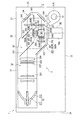
図1は、プロジェクター1の内部構成を模式的に示す平面図である。
なお、以下では、説明の便宜上、後述する投射レンズ36が配置される側を「前面」とし、その反対側を「背面」とする。
プロジェクター1は、画像情報に応じて光束を変調してスクリーン(図示略)上に投射する。このプロジェクター1は、図1に示すように、外装を構成する外装筐体2と、外装筐体2内部に配設される光学ユニット3及び冷却装置4(図1では一部の構成部材(冷却ファン5)のみを図示)とを備える。
[First embodiment]
DESCRIPTION OF EXEMPLARY EMBODIMENTS Hereinafter, a first embodiment of the invention will be described with reference to the drawings.
[Configuration of projector]
FIG. 1 is a plan view schematically showing the internal configuration of the projector 1.
In the following, for convenience of explanation, a side on which a
The projector 1 modulates a light beam according to image information and projects it on a screen (not shown). As shown in FIG. 1, the projector 1 includes an
〔外装筐体の構成〕
外装筐体2は、図1に示すように、天面部(図示略)及び底面部21と、側面部22〜25(以下、前面側の側面部を前面部22、背面側の側面部を背面部23)とを備え、略直方体形状を有する。
[Configuration of exterior casing]
As shown in FIG. 1, the
〔光学ユニットの構成〕
光学ユニット3は、画像情報(画像信号)に応じて変調して投射するものであり、図1に示すように、背面部23に沿って延出するとともに、一端側が前面部22に向けて延出する平面視略L字形状を有する。
この光学ユニット3は、図1に示すように、光源ランプ311及びリフレクター312を有する光源装置31と、レンズアレイ321,322、偏光変換素子323、及び重畳レンズ324を有する照明光学装置32と、ダイクロイックミラー331,332、及び反射ミラー333を有する色分離光学装置33と、入射側レンズ341、リレーレンズ343、及び反射ミラー342,344を有するリレー光学装置34と、光変調装置としての3つの液晶パネル351、3つの入射側偏光板352、3つの出射側偏光板353、及び色合成光学装置としてのクロスダイクロイックプリズム354を有する光学装置35と、投射光学装置としての投射レンズ36と、これら各部材31〜35を内部に収納するとともに投射レンズ36を支持する光学部品用筐体37とを備える。
[Configuration of optical unit]
The
As shown in FIG. 1, the
そして、光学ユニット3では、上述した構成により、光源装置31から出射され照明光学装置32を介した光束は、色分離光学装置33にてR,G,Bの3つの色光に分離される。また、分離された各色光は、各液晶パネル351にて画像情報に応じてそれぞれ変調される。変調された各色光は、プリズム354にて合成されて、投射レンズ36にてスクリーンに投射される。
なお、図1では、説明の便宜上、R色光側の液晶パネル351、入射側偏光板352、及び出射側偏光板353をR側部材350Rとし、G色光側及びB色光側も同様にG側部材350G及びB側部材350Bとしている。以降の図も同様である。
また、図1では、R,G,Bの各色光側の各液晶パネル351をそれぞれ液晶パネル351R(赤側光変調装置),351G(緑側光変調装置),351B(青側光変調装置)としている。以降の図も同様である。
In the
In FIG. 1, for convenience of explanation, the
In FIG. 1, the
〔冷却装置の構成〕
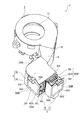
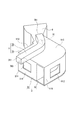
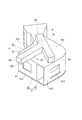
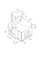
図2または図3は、冷却装置4の構成を模式的に示す図である。具体的に、図2は冷却装置4を背面上方側(外装筐体2の天面部側)から見た斜視図であり、図3は図2においてダクト6の蓋体92を取り外した図である。
冷却装置4は、図1に示すように、投射レンズ36に近接して設けられ、光学装置35に空気を送風して冷却する。この冷却装置4は、図1ないし図3に示すように、冷却ファン5と、ダクト6(図2、図3)とを備える。
[Configuration of cooling device]
FIG. 2 or FIG. 3 is a diagram schematically showing the configuration of the
As shown in FIG. 1, the
〔冷却ファンの構成〕
冷却ファン5は、ファン回転方向に対して前向きに曲がった複数の羽根を有する、所謂、シロッコファンで構成され、投射レンズ36に対して前面側から見て右側方に配設されている。
より具体的に、冷却ファン5は、図2または図3に示すように、空気を吸入する吸入口51が上方側に向き、空気を吐出する吐出口52が前面側から見て左斜め後方(B側部材350Bの前面側)に向くように配設されている。
[Configuration of cooling fan]
The cooling
More specifically, as shown in FIG. 2 or FIG. 3, the cooling
〔ダクトの構成〕
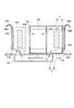
図4は、ダクト6の構成を模式的に示す図である。具体的に、図4は、ダクト6を背面下方側(底面部21側)から見た斜視図である。
ダクト6は、冷却ファン5から吐出された空気を各部材350R,350G,350Bに送風する。このダクト6は、図2ないし図4に示すように、第1ダクト部としてのメインダクト部7Aと、第2ダクト部としての補助ダクト部7Bとを備える。
[Duct structure]
FIG. 4 is a diagram schematically showing the configuration of the
The
〔メインダクト部の構成〕
メインダクト部7Aは、図2ないし図4に示すように、導入側ダクト部8と、主流路形成部9とを備える。
導入側ダクト部8は、筒形状を有し、図2ないし図4に示すように、一端(ダクト6内部に空気を導入させるための導入口)が冷却ファン5の吐出口52に接続し、吐出口52からの空気の吐出方向に沿って延出するように形成されている。そして、導入側ダクト部8は、他端が主流路形成部9に接続し、主流路形成部9内部に連通する。
[Configuration of main duct section]
As shown in FIGS. 2 to 4, the main duct portion 7 </ b> A includes an introduction-
The introduction-
主流路形成部9は、冷却ファン5から吐出され導入側ダクト部8を介した空気を、B側部材350B、G側部材350Gの順に流通させる。この主流路形成部9は、図2ないし図4に示すように、本体部91と、蓋体92(図2、図4)とを備える。
本体部91は、図2ないし図4に示すように、内周壁91A(図3、図4)、外周壁91B、及び底壁91Cを有する容器状に形成されている。
内周壁91Aは、プリズム354におけるR,G,Bの各色光が入射する各光入射面354R,354G,354B(図1、図3)を囲む平面視略U字形状を有する。
この内周壁91Aには、各部材350R,350G,350Bを介した各R,G,Bの各色光をプリズム354に入射させるための3つの開口部911(図4参照、図4ではR色光側の開口部911のみ図示)が形成されている。
そして、内周壁91Aには、図2または図3に示すように、各光入射面354R,354G,354Bにそれぞれ対向するように、液晶パネル351及び出射側偏光板353が支持部材355を介してそれぞれ取り付けられる。
The main flow
As shown in FIGS. 2 to 4, the
The inner
The inner
As shown in FIG. 2 or FIG. 3, the inner
また、内周壁91Aにおける前面側の端部同士は、プリズム354における合成された画像が出射される光出射面354E(図1、図3)を覆うように接続壁91D(図3、図4)により接続されている。
この接続壁91Dには、プリズム354にて合成され光を通過させるための開口部913(図5参照)が形成されている。
この接続壁91Dは、プリズム354にて合成された光のみを開口部913を介して通過させ、不要な光(漏れ光)を遮光して投射レンズ36に入射することを防止する機能を有している。
Further, the front end portions of the inner
In this
The
外周壁91Bは、内周壁91Aに対してG,Bの各色光の入射側に位置し、内周壁91Aに略平行となる平面視略L字形状を有する。
この外周壁91Bには、各入射側偏光板352を介したG,Bの各色光を通過させるための2つの開口部912(図4参照、図4ではG色光側の開口部912のみ図示)が形成されている。
そして、外周壁91Bには、図2または図3に示すように、2つの入射側偏光板352が各偏光板保持部材356G,356Bを介して2つの開口部912を閉塞するようにそれぞれ配設されている。
The outer
The outer
As shown in FIG. 2 or FIG. 3, two incident-side
ここで、各偏光板保持部材356G,356Bは、図2または図3に示すように、同様に構成されている。以下では、偏光板保持部材356Gについてのみ説明する。
偏光板保持部材356Gは、中央に開口部3561を有する板体で構成されている。そして、入射側偏光板352は、開口部3561を閉塞するように偏光板保持部材356Gに取り付けられる。
この偏光板保持部材356Gにおいて、上方側の端部には、図2または図3に示すように、光入射側に折り曲げられ、上方に向けて凸となる湾曲形状を有する位置調整部3562が設けられている。
より具体的に、位置調整部3562は、入射側偏光板352に入射する色光の光軸を中心とする円弧状となるように湾曲されている。
この位置調整部3562は、具体的な図示は省略したが、光学部品用筐体37の上面に設けられた調整受け部上に摺動可能に載置される。そして、入射側偏光板352は、前記調整受け部上で位置調整部3562が摺動することで、入射する色光の光軸を中心として回転する。すなわち、偏光板保持部材356Gは、入射側偏光板352を保持する機能の他、入射側偏光板352の位置を調整する機能も有する。
Here, each polarizing
The polarizing
In the polarizing
More specifically, the
Although not specifically shown, the
また、R色光側の偏光板保持部材356Rは、図2または図3に示すように、上述した各偏光板保持部材356G,356Bと略同様の構成を有するが、以下の点が異なる。
すなわち、偏光板保持部材356Rにおいて、R色光の入射側から見て左側の端部には、図2または図3に示すように、光出射側に折り曲げられた遮蔽板としての略矩形状の遮蔽部3563が形成されている。
このため、偏光板保持部材356Rを配設した状態では、遮蔽部3563により、液晶パネル351G(G側部材350G)と液晶パネル351R(R側部材350R)とが区画されることとなる。
Further, the polarizing
That is, in the polarizing
Therefore, in a state where the polarizing
底壁91Cは、図4に示すように、内周壁91A及び外周壁91Bの下方側の各端部同士を接続するとともに、底面部21に沿って水平方向に延出し、プリズム354の下方側を閉塞するように形成されている。
As shown in FIG. 4, the
〔補助ダクト部の構成〕
補助ダクト部7Bは、図4に示すように、底壁91Cの外面に取り付けられ、メインダクト部7A内部の流路C2(図5参照)を流通する空気の一部をR側部材350Rに導く。
この補助ダクト部7Bは、中空部材で構成され、一端7B1(図4)から他端7B2(図4)に向けて底壁91Cの外面に沿って延出するように形成されている。
より具体的に、一端7B1は、鉛直方向からの平面視で、B側部材350Bの前面側の端部位置に位置付けられる。また、補助ダクト部7Bは、鉛直方向からの平面視で、一端7B1からプリズム354の略中心位置に向けて延出し、さらに光入射面354Rに直交する方向に沿って直線状に延出する。そして、他端7B2は、鉛直方向からの平面視で、R側部材350Rの前後方向(前面から背面への方向)の略中心位置に位置付けられる。
[Configuration of auxiliary duct]
As shown in FIG. 4, the
The
More specifically, the one end 7B1 is positioned at the front end position of the B-
上述した補助ダクト部7Bにおいて、一端7B1側の上面部分は、図4に示すように、メインダクト部7A内部(流路C2)と連通口7Cを介して連通する。
この連通口7Cは、鉛直方向からの平面視で、斜辺が冷却ファン5からの吐出方向に沿い、他の各辺が光入射面354B及び光出射面354Eに略平行する略直角三角形状を有する(図5参照)。
また、連通口7Cは、鉛直方向からの平面視で、液晶パネル351Bに一部が重なり合う位置に設けられている(図5参照)。
さらに、補助ダクト部7Bにおいて、他端7B2側の上面部分には、図4に示すように、連通口7Cを介して導入した空気を外部に排出するための排出口7B3が形成されている。
In the
The communication port 7 </ b> C has a substantially right triangle shape in which the oblique side is along the discharge direction from the cooling
Further, the
Further, in the
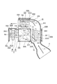
〔ダクトの流路〕
図5及び図6は、ダクト6の流路を説明するための図である。具体的に、図5は内周壁91Aや外周壁91Bを通る水平面でダクト6を切断した断面を上方側から見た図であり、図6は補助ダクト部7Bを通る鉛直面でダクト6を切断した断面を前面側から見た図である。
なお、図5及び図6では、説明の便宜上、光学装置35を構成する各出射側偏光板353及び各支持部材355の図示を省略している。
次に、上述したダクト6の流路について説明する。
先ず、メインダクト部7A内部には、本体部91の上方側が蓋体92により閉塞されることで、図5に示すように、流路C1,C2が形成される。
すなわち、冷却ファン5から吐出された空気は、導入側ダクト部8内部の流路C1に沿って流通し、メインダクト部7A内部に導入され、液晶パネル351Bの側方(前面側の端部)に送風される。
そして、メインダクト部7A内部に導入された空気は、平面視L字状の流路C2に沿って、各部材350B,350Gの側方から、B側部材350B、G側部材350Gの順に流通する。流路C2を辿る空気は、各液晶パネル351B,351Gの光入射側及び光出射側を流通し、各部材350B,350Gを冷却する。
[Duct flow path]
5 and 6 are diagrams for explaining the flow path of the
In FIGS. 5 and 6, for convenience of explanation, the illustration of the emission-side
Next, the flow path of the
First, in the
That is, the air discharged from the cooling
The air introduced into the
また、補助ダクト部7Bは、連通口7Cを介して流路C2と連通することで、図5または図6に示すように、内部に流路C3が形成される。
すなわち、メインダクト部7A内部に導入され、流路C2を辿る空気の一部は、図5または図6に示すように、連通口7Cを介して流路C3に分岐され、R側部材350Rの下方側に導かれ、排出口7B3から補助ダクト部7B外部に排出される。
そして、補助ダクト部7B外部に排出された空気は、液晶パネル351Rの下方側端部に送風され、下方側から上方側に向けて、液晶パネル351Rの光入射側及び光出射側を流通し、R側部材350Rを冷却する。
Further, the
That is, a part of the air introduced into the
Then, the air discharged to the outside of the
上述した第1実施形態によれば、以下の効果がある。
本実施形態では、各部材350R,350G,350Bに空気を導くダクト6は、2つの液晶パネル351B,351Gの側方から順に空気を流通させるメインダクト部7Aを備える。
このことにより、従来のダクトと比較して、メインダクト部7Aの流路長さを短くできるとともに、メインダクト部7Aに配設される液晶パネル351の数も少なくなるので、メインダクト部7A内部の静圧を低下させることができる。このため、冷却ファン5からメインダクト部7Aに吐出される空気の風量を十分に確保することができ、流路C1,C2を辿る空気により各部材350G,350Bを効果的に冷却できる。
The first embodiment described above has the following effects.
In the present embodiment, the
As a result, the flow path length of the
また、ダクト6は、メインダクト部7Aの他、メインダクト部7Aから分岐され、流路C2を辿る空気の一部をR側部材350Rに導く補助ダクト部7Bを備える。
このことにより、補助ダクト部7Bを介した空気をR側部材350Rに送風することができ、R側部材350Rも効果的に冷却できる。
以上のように、メインダクト部7A及び補助ダクト部7Bに空気を流通させることで、全ての部材350R,350G,350Bを効果的に冷却できる。
In addition to the
Thereby, the air through the
As described above, all
また、補助ダクト部7Bがプリズム354の下方側に設けられているため、補助ダクト部7Bをデッドスペースに配設できる。このため、ダクト6をプロジェクター1内部に配設した場合であっても、他の部材に機械的に干渉することがなく、他の部材のレイアウトを変更する必要がない。特に、デッドスペースに補助ダクト部7Bを配設することで、プロジェクター1の薄型化を阻害することがない。
Further, since the
本実施形態では、メインダクト部7A及び補助ダクト部7Bの構成により、メインダクト部7Aを流通する空気の風量は、補助ダクト部7Bを流通する空気の風量に対して多い。
そして、メインダクト部7AにG側部材350G及びB側部材350Bが配設され、補助ダクト部7Bから送風される空気によりR側部材350Rを冷却している。
このことにより、発熱量が少ないため少ない風量でも十分に冷却できるR側部材350Rについては補助ダクト部7Bから送風される少ない風量の空気にて冷却できる。また、発熱量が多いため多くの風量を必要とする各部材350B,350Gについてはメインダクト部7Aを流通する風量の多い空気にて冷却できる。
したがって、各部材350R,350G,350Bの発熱量に応じて、各部材350R,350G,350Bを効率的に冷却できる。
In the present embodiment, due to the configuration of the
A G-
Accordingly, the R-
Therefore, each
また、メインダクト部7Aにおいて、流路C2の上流側にB側部材350Bが配設され、下流側にG側部材350Gが配設されている。
このことにより、比較的に温度の低い空気(各部材350B,350Gにて温められていない空気)にて低い目標温度の液晶パネル351B(B側部材350B)を冷却することで、液晶パネル351Bを目標温度に近付けることができる。また、液晶パネル351Bよりも目標温度の高い液晶パネル351G(G側部材350G)については、B側部材350Bを介した空気にて冷却することで、液晶パネル351Gについても目標温度に近付けることができる。
したがって、G側部材350G及びB側部材350Bを効率的に冷却できる。
In the
Accordingly, the
Therefore, the
さらに、偏光板保持部材356Rが遮蔽部3563を備えるので、メインダクト部7Aを流通した後の空気、すなわち、G側部材350G及びB側部材350Bを冷却した後の温度の高い空気が、R側部材350R側に回り込むことを防止できる。このため、メインダクト部7Aを流通した後の温度の高い空気によるR側部材350Rの温度上昇を回避し、補助ダクト部7Bを介した空気にてR側部材350Rを効果的に冷却できる。
Furthermore, since the polarizing
また、連通口7Cは鉛直方向からの平面視で液晶パネル351Bに一部が重なり合う位置に形成されているので、連通口7Cを介して、各部材350G,350Bにて温められる前の空気を補助ダクト部7Bに導入することができる。したがって、比較的に低い温度の空気をR側部材350Rに送風することができ、R側部材350Rを効果的に冷却できる。
さらに、連通口7Cを上述した位置に形成することで、補助ダクト部7Bを上述したデッドスペース(プリズム354の下方側)に配設しやすい構成となる。このため、他の部材のレイアウトを変更する必要がなく、また、プロジェクター1の薄型化を阻害することもない。
Further, since the
Furthermore, by forming the
[第2実施形態]
次に、本発明の第2実施形態を図面に基づいて説明する。
以下の説明では、前記第1実施形態と同様の構造及び同一部材には同一符号を付し、その詳細な説明は省略または簡略化する。
図7は、第2実施形態におけるダクト6の構成を模式的に示す図である。具体的に、図7は、ダクト6を背面下方側から見た斜視図である。
本実施形態は、前記第1実施形態に対して、補助ダクト部7Bの構成が異なるのみである。その他の構成は、前記第1実施形態と同様のものである。
具体的に、第2実施形態における補助ダクト部7Bは、図7に示すように、一端7B1側から他端側に向けて2つに分岐し、第1分岐ダクト部11と、第2分岐ダクト部12とを備える。
[Second Embodiment]
Next, 2nd Embodiment of this invention is described based on drawing.
In the following description, the same structure and the same members as those in the first embodiment are denoted by the same reference numerals, and detailed description thereof is omitted or simplified.
FIG. 7 is a diagram schematically showing the configuration of the
The present embodiment differs from the first embodiment only in the configuration of the
Specifically, as shown in FIG. 7, the auxiliary duct portion 7 </ b> B in the second embodiment branches into two from the one end 7 </ b> B <b> 1 side toward the other end side, and the first
第1分岐ダクト部11は、図7に示すように、前記第1実施形態で説明した他端7B2側と同様の構成であり、排出口7B3(以下、第1排出口7B3)を有する。
第2分岐ダクト部12は、図7に示すように、鉛直方向からの平面視で、一端7B1からG側部材350Gの配設位置における左右方向(前面側から見て左右方向)の略中心位置まで略直線状に延びるように形成されている。
そして、上述した第2分岐ダクト部12において、先端側の上面部分は、図7に示すように、メインダクト部7A内部(流路C2)と第2排出口7B4を介して連通する。
この第2排出口7B4は、鉛直方向からの平面視で、液晶パネル351Gにおける左右方向(前面側から見て左右方向)の略中心位置に位置するように形成されている。
As shown in FIG. 7, the first
As shown in FIG. 7, the second
And in the 2nd
The second discharge port 7B4 is formed so as to be positioned at a substantially central position in the left-right direction (left-right direction when viewed from the front side) of the
次に、第2実施形態におけるダクト6の流路について説明する。
図8は、第2実施形態におけるダクト6の流路を説明するための図である。具体的に、図8は、内周壁91Aや外周壁91Bを通る水平面でダクト6を切断した断面を上方側型見た図である。
なお、以下では、前記第1実施形態で説明したダクト6の流路と異なる部分のみを説明する。
連通口7Cを介して空気を補助ダクト部7Bに流入させる流路C3は、上述した各分岐ダクト部11,12により、2つの流路C31,C32に分岐される。
流路C31を辿る空気は、前記第1実施形態と同様に、図8に示すように、R側部材350Rの下方側端部に導かれ、第1排出口7B3を介して液晶パネル351Rの下方側端部に送風される。
Next, the flow path of the
FIG. 8 is a view for explaining the flow path of the
In the following, only the portions different from the flow path of the
The flow path C3 through which air flows into the
As in the first embodiment, the air that follows the flow path C31 is guided to the lower end portion of the R-
一方、流路C32を辿る空気は、図8に示すように、液晶パネル351Gの下方側に導かれ、第2排出口7B4を介して流路C2に流入する。
そして、流路C2に流入した空気は、液晶パネル351Gの下方側端部に送風され、下方側から上方側に向けて、液晶パネル351Gの光入射側及び光出射側を流通し、G側部材350Gを冷却する。
ここで、流路C32は、上述した第2分岐ダクト部12の形状により、鉛直方向からの平面視で、図8に示すように、流入先である流路C2と鋭角を成して交差するように形成されている。したがって、流路C32を辿り、第2排出口7B4を介して補助ダクト部7B外部に排出される空気は、円滑に流路C2に流入することとなる。
On the other hand, as shown in FIG. 8, the air that follows the flow path C32 is guided to the lower side of the
The air flowing into the flow path C2 is blown to the lower end portion of the
Here, the flow path C32 intersects with the flow path C2 that is an inflow destination at an acute angle as shown in FIG. 8 in a plan view from the vertical direction due to the shape of the second
上述した第2実施形態によれば、前記第1実施形態と同様の効果の他、以下の効果がある。
本実施形態では、補助ダクト部7Bが各分岐ダクト部11,12を備えるので、メインダクト部7Aを流通する空気、及び第2分岐ダクト部12を介して送風される空気の双方により、G側部材350Gを冷却できる。
特に、G側部材350Gは、冷却に多くの風量を必要とするため、補助ダクト部7Bを上述した構成とすることで、G側部材350Gを効果的に冷却できる。
According to the second embodiment described above, there are the following effects in addition to the same effects as in the first embodiment.
In the present embodiment, since the
In particular, since the G-
[第3実施形態]
次に、本発明の第3実施形態を図面に基づいて説明する。
以下の説明では、前記第1実施形態と同様の構造及び同一部材には同一符号を付し、その詳細な説明は省略または簡略化する。
図9は、第3実施形態におけるダクト6の構成を模式的に示す図である。具体的に、図9は、ダクト6を背面下方側から見た斜視図である。
本実施形態では、前記第1実施形態に対して、偏光板保持部材356Rの構成、及び補助ダクト部7Bの形状が異なるのみである。その他の構成は、前記第1実施形態と同様のものである。
具体的に、第3実施形態における偏光板保持部材356Rは、遮蔽部3563が省略されている(図10参照)。
また、第3実施形態における補助ダクト部7Bは、鉛直方向からの平面視で、一端7B1から光入射面354Rに直交する方向に沿って直線状に延出し、他端7B2側が背面側に延出するように形成されている(図10参照)。
そして、他端7B2側に形成された排出口7B3は、鉛直方向からの平面視で、R側部材350Rの前面側に位置付けられている(図10参照)。
[Third embodiment]
Next, 3rd Embodiment of this invention is described based on drawing.
In the following description, the same structure and the same members as those in the first embodiment are denoted by the same reference numerals, and detailed description thereof is omitted or simplified.
FIG. 9 is a diagram schematically showing the configuration of the
In the present embodiment, only the configuration of the polarizing
Specifically, in the polarizing
In addition, the
The discharge port 7B3 formed on the other end 7B2 side is positioned on the front side of the R-
次に、第3実施形態におけるダクト6の流路について説明する。
図10は、第3実施形態におけるダクト6の流路を説明するための図である。具体的に、図10は、内周壁91Aや外周壁91Bを通る水平面でダクト6を切断した断面を上方側から見た図である。
なお、以下では、前記第1実施形態で説明したダクト6の流路とは異なる部分のみを説明する。
流路C3を辿る空気は、図10に示すように、R側部材350Rの下方側端部に導かれ、排出口7B3を介して液晶パネル351Rの下方側端部に送風される。
そして、液晶パネル351Rの下方側端部に送風された空気は、上述した補助ダクト部7Bの他端7B2側の屈曲した形状により、下方側から上方側にかけて、前面側から背面側に向うように、液晶パネル351Rの光入射側及び光出射側を流通し、R側部材350Rを冷却する。
すなわち、流路C3を介して液晶パネル351Rに送風された空気の流通方向D1は、図10に示すように、流路C2を介した後の空気の流通方向D2に交差することとなる。
Next, the flow path of the
FIG. 10 is a view for explaining the flow path of the
In the following, only a portion different from the flow path of the
As shown in FIG. 10, the air that follows the flow path C3 is guided to the lower end portion of the R-
The air blown to the lower end portion of the
That is, the flow direction D1 of the air blown to the
上述した第3実施形態によれば、前記第1実施形態と同様の効果の他、以下の効果がある。
本実施形態では、補助ダクト部7Bは、流路C3を介して液晶パネル351Rに送風された空気の流通方向D1がメインダクト部7Aを介した後の空気の流通方向D2に交差するように設けられている。
このことにより、補助ダクト部7Bを介して送風される空気により、メインダクト部7Aを流通した後の温度の高い空気がR側部材350R側に回り込むことを防止できる。このため、メインダクト部7Aを流通した後の温度の高い空気によるR側部材350Rの温度上昇を回避し、補助ダクト部7Bを介した空気にてR側部材350Rを効果的に冷却できる。
したがって、偏光板保持部材356Rに遮蔽部3563を設ける必要がなく、偏光板保持部材356Rの形状の簡素化が図れる。
According to the third embodiment described above, there are the following effects in addition to the same effects as in the first embodiment.
In the present embodiment, the
Accordingly, it is possible to prevent high-temperature air after flowing through the
Therefore, it is not necessary to provide the
なお、本発明は前述の実施形態に限定されるものではなく、本発明の目的を達成できる範囲での変形、改良等は本発明に含まれるものである。
前記各実施形態では、冷却ファン5として、シロッコファンを採用していたが、これに限らず、ファン回転方向に対して後向きに曲がった複数の羽根を有するターボファンや、ファン回転軸に沿って空気を吸入及び吐出する軸流ファンを採用しても構わない。
前記各実施形態では、補助ダクト部7Bは、プリズム354の下方側に配設されていたが、これに限らず、プリズム354の上方側に配設しても構わない。
It should be noted that the present invention is not limited to the above-described embodiments, and modifications, improvements, and the like within the scope that can achieve the object of the present invention are included in the present invention.
In each of the embodiments described above, a sirocco fan is employed as the cooling
In each of the above embodiments, the
前記各実施形態では、メインダクト部7Aにおいて、流路C2の上流側からB側部材350B、G側部材350Gの順に配設されていたが、これに限らず、G側部材350G、B側部材350Bの順に配設しても構わない。
前記各実施形態では、本発明に係る遮蔽板を偏光板保持部材356Rに設けていたが、これに限らず、その他の部材、例えば、R色光側の支持部材355や、光学部品用筐体37に設けても構わない。
前記各実施形態において、連通口7Cの形成位置は、前記各実施形態で説明した位置に限らず、いずれの位置に形成しても構わない。なお、R側部材350Rの冷却効率を考慮した場合には、B側部材350Bと冷却ファン5との間の流路C1,C2に連通するように構成することが好ましい。
In each of the above embodiments, in the
In each of the above embodiments, the shielding plate according to the present invention is provided on the polarizing
In each of the above embodiments, the formation position of the
前記各実施形態では、各部材350R,350G,350Bから出射されたR,G,Bの各色光を合成する構成としてクロスダイクロイックプリズム354を採用していたが、これに限らず、複数のダイクロイックミラーを用いた構成としても構わない。
前記各実施形態において、プロジェクター1は、3つの液晶パネル351を備える構成としたが、本発明はこれに限らない。すなわち、2つ、あるいは、4つ以上の液晶パネルを用いたプロジェクターにも、本発明を適用可能である。
前記各実施形態において、光変調装置としては、透過型の液晶パネルの他、反射型の液晶パネルを採用しても構わない。
前記実施形態では、フロント投射型のプロジェクターの例のみを挙げたが、本発明は、スクリーンを備え、該スクリーンの裏面側から投射を行うリアタイプのプロジェクターにも適用可能である。
In each of the above embodiments, the cross
In each of the above embodiments, the projector 1 is configured to include the three
In each of the above embodiments, as the light modulation device, a reflective liquid crystal panel may be adopted in addition to a transmissive liquid crystal panel.
In the above embodiment, only an example of a front projection type projector has been described. However, the present invention can also be applied to a rear type projector that includes a screen and performs projection from the back side of the screen.
本発明は、プレゼンテーションやホームシアター等に用いられるプロジェクターに利用できる。 The present invention can be used for projectors used in presentations, home theaters, and the like.
1・・・プロジェクター、4・・・冷却装置、5・・・冷却ファン、6・・・ダクト、7A・・・メインダクト部(第1ダクト部)、7B・・・補助ダクト部(第2ダクト部)、7C・・・連通口、11・・・第1分岐ダクト部、12・・・第2分岐ダクト部、351R・・・液晶パネル(赤側光変調装置)、351G・・・液晶パネル(緑側光変調装置)、351B・・・液晶パネル(青側光変調装置)、354・・・クロスダイクロイックプリズム(色合成光学装置)、354R,354G,354B・・・光入射面、3563・・・遮蔽部(遮蔽板)、C1〜C3,C31,C32・・・流路、D1,D2・・・流通方向。 DESCRIPTION OF SYMBOLS 1 ... Projector, 4 ... Cooling device, 5 ... Cooling fan, 6 ... Duct, 7A ... Main duct part (1st duct part), 7B ... Auxiliary duct part (2nd Duct portion), 7C ... communication port, 11 ... first branch duct portion, 12 ... second branch duct portion, 351R ... liquid crystal panel (red side light modulator), 351G ... liquid crystal Panel (green side light modulation device), 351B ... Liquid crystal panel (blue side light modulation device), 354 ... Cross dichroic prism (color synthesis optical device), 354R, 354G, 354B ... Light incident surface, 3563 ... shielding part (shielding plate), C1 to C3, C31, C32 ... flow path, D1, D2 ... flow direction.
Claims (8)
前記冷却装置は、
空気を吸入して吐出する冷却ファンと、
前記冷却ファンからの空気を前記複数の光変調装置に導くダクトとを備え、
前記ダクトは、
2つの前記光変調装置の側方から順に空気を流通させる第1ダクト部と、
前記第1ダクト部に連通し、前記第1ダクト部を流通する空気の一部を他の前記光変調装置に導く第2ダクト部とを備える
ことを特徴とするプロジェクター。 A projector comprising a plurality of light modulation devices that respectively modulate a plurality of color lights, and a cooling device that cools the light modulation device,
The cooling device is
A cooling fan that sucks and discharges air;
A duct for guiding air from the cooling fan to the plurality of light modulation devices,
The duct is
A first duct portion for circulating air in order from the side of the two light modulation devices;
A projector comprising: a second duct portion that communicates with the first duct portion and guides a part of the air flowing through the first duct portion to the other light modulation device.
前記複数の光変調装置にて変調された各色光が入射する複数の光入射面を有し、前記各色光を合成する色合成光学装置を備え、
前記第2ダクト部は、
前記複数の光入射面に交差する端面に対向するように設けられている
ことを特徴とするプロジェクター。 The projector according to claim 1.
A plurality of light incident surfaces on which each color light modulated by the plurality of light modulation devices is incident; and a color combining optical device that combines the color lights.
The second duct part is
The projector is provided so as to face an end surface intersecting the plurality of light incident surfaces.
前記複数の光変調装置は、
赤色光を変調する赤側光変調装置と、緑色光を変調する緑側光変調装置と、青色光を変調する青側光変調装置とを備え、
前記第1ダクト部は、
前記緑側光変調装置及び前記青側光変調装置に空気を流通させ、
前記第2ダクト部は、
前記赤側光変調装置に空気を導く
ことを特徴とするプロジェクター。 The projector according to claim 1 or 2,
The plurality of light modulation devices include:
A red side light modulation device that modulates red light, a green side light modulation device that modulates green light, and a blue side light modulation device that modulates blue light,
The first duct part is
Air is circulated through the green side light modulation device and the blue side light modulation device,
The second duct part is
A projector that guides air to the red-side light modulator.
前記緑側光変調装置及び前記青側光変調装置は、
前記第1ダクト部における流路上流側から前記青側光変調装置、前記緑側光変調装置の順に配設されている
ことを特徴とするプロジェクター。 The projector according to claim 3.
The green side light modulation device and the blue side light modulation device are:
The projector is characterized in that the blue side light modulation device and the green side light modulation device are arranged in this order from the upstream side of the flow path in the first duct portion.
前記第2ダクト部は、
前記第2ダクト部における流路下流側が分岐し、前記他の光変調装置に空気を導く第1分岐ダクト部、及び前記2つの光変調装置のうち前記第1ダクト部における流路下流側の前記光変調装置に空気を導く第2分岐ダクト部を備える
ことを特徴とするプロジェクター。 The projector according to any one of claims 1 to 4,
The second duct part is
The downstream side of the flow path in the second duct part branches off, the first branch duct part that guides air to the other light modulation device, and the downstream side of the flow path in the first duct part of the two light modulation devices A projector comprising a second branch duct for guiding air to the light modulator.
前記2つの光変調装置のうち前記第1ダクト部における流路下流側の前記光変調装置と前記他の光変調装置とを区画する遮蔽板を備える
ことを特徴とするプロジェクター。 The projector according to any one of claims 1 to 5,
A projector comprising: a shielding plate that partitions the light modulation device on the downstream side of the flow path in the first duct portion and the other light modulation device among the two light modulation devices.
前記第2ダクト部は、
前記第2ダクト部を介して前記他の光変調装置に送風される空気の流通方向が前記第1ダクト部を介して前記2つの光変調装置を流通した後の空気の流通方向に交差するように設けられている
ことを特徴とするプロジェクター。 The projector according to any one of claims 1 to 5,
The second duct part is
The flow direction of the air blown to the other light modulation device via the second duct portion intersects the flow direction of the air after flowing through the two light modulation devices via the first duct portion. A projector characterized by being provided in
前記第2ダクト部における前記第1ダクト部に連通する連通口は、
当該プロジェクターの厚み方向からの平面視で、前記2つの光変調装置のうち前記第1ダクト部における流路上流側の前記光変調装置に一部が重なり合うように形成されている
ことを特徴とするプロジェクター。 The projector according to any one of claims 1 to 7,
The communication port communicating with the first duct part in the second duct part is
In the plan view from the thickness direction of the projector, the two light modulation devices are formed so as to partially overlap the light modulation device on the upstream side of the flow path in the first duct portion. projector.
Priority Applications (6)
| Application Number | Priority Date | Filing Date | Title |
|---|---|---|---|
| JP2010075014A JP5407982B2 (en) | 2010-03-29 | 2010-03-29 | projector |
| EP11158925.5A EP2375283B1 (en) | 2010-03-29 | 2011-03-18 | Projector |
| CN201110080107.8A CN102207665B (en) | 2010-03-29 | 2011-03-25 | projector |
| TW100110473A TWI428681B (en) | 2010-03-29 | 2011-03-25 | Projector |
| KR1020110027593A KR20110109941A (en) | 2010-03-29 | 2011-03-28 | Projector |
| US13/074,355 US8757811B2 (en) | 2010-03-29 | 2011-03-29 | Projector |
Applications Claiming Priority (1)
| Application Number | Priority Date | Filing Date | Title |
|---|---|---|---|
| JP2010075014A JP5407982B2 (en) | 2010-03-29 | 2010-03-29 | projector |
Related Child Applications (1)
| Application Number | Title | Priority Date | Filing Date |
|---|---|---|---|
| JP2013230045A Division JP5652535B2 (en) | 2013-11-06 | 2013-11-06 | projector |
Publications (2)
| Publication Number | Publication Date |
|---|---|
| JP2011209400A JP2011209400A (en) | 2011-10-20 |
| JP5407982B2 true JP5407982B2 (en) | 2014-02-05 |
Family
ID=44063864
Family Applications (1)
| Application Number | Title | Priority Date | Filing Date |
|---|---|---|---|
| JP2010075014A Expired - Fee Related JP5407982B2 (en) | 2010-03-29 | 2010-03-29 | projector |
Country Status (6)
| Country | Link |
|---|---|
| US (1) | US8757811B2 (en) |
| EP (1) | EP2375283B1 (en) |
| JP (1) | JP5407982B2 (en) |
| KR (1) | KR20110109941A (en) |
| CN (1) | CN102207665B (en) |
| TW (1) | TWI428681B (en) |
Families Citing this family (9)
| Publication number | Priority date | Publication date | Assignee | Title |
|---|---|---|---|---|
| JP6179152B2 (en) * | 2013-03-26 | 2017-08-16 | セイコーエプソン株式会社 | Light source device and projector |
| JP2015222305A (en) * | 2014-05-22 | 2015-12-10 | カシオ計算機株式会社 | Image projection device |
| JP6726401B2 (en) * | 2016-08-23 | 2020-07-22 | 株式会社リコー | Light source device, image projection device, and method for arranging light source device |
| WO2020149048A1 (en) * | 2019-01-17 | 2020-07-23 | ソニー株式会社 | Spatial light modulating module, spatial light modulating element, light shielding plate, and projection type display device |
| JP2020201303A (en) * | 2019-06-06 | 2020-12-17 | セイコーエプソン株式会社 | projector |
| JP2020201426A (en) | 2019-06-12 | 2020-12-17 | セイコーエプソン株式会社 | projector |
| JP6888648B2 (en) | 2019-07-10 | 2021-06-16 | セイコーエプソン株式会社 | projector |
| CN211348977U (en) * | 2020-02-07 | 2020-08-25 | 中强光电股份有限公司 | Opto-mechanical modules and projectors |
| CN113219719B (en) * | 2021-04-23 | 2023-06-30 | 成都京东方显示科技有限公司 | Backlight module, liquid crystal module and display device |
Family Cites Families (23)
| Publication number | Priority date | Publication date | Assignee | Title |
|---|---|---|---|---|
| US6481854B1 (en) * | 1998-12-28 | 2002-11-19 | Fujitsu Limited | Projection type display apparatus having air cooling arrangement |
| JP4030208B2 (en) | 1998-12-28 | 2008-01-09 | 富士通株式会社 | Projection display |
| JP2000231154A (en) | 1999-02-10 | 2000-08-22 | Hitachi Ltd | Display device and display optical system |
| JP2001133885A (en) * | 1999-08-26 | 2001-05-18 | Mitsubishi Electric Corp | projector |
| JP2001188305A (en) | 1999-12-28 | 2001-07-10 | Canon Inc | projector |
| JP3673692B2 (en) | 2000-03-29 | 2005-07-20 | Necビューテクノロジー株式会社 | Liquid crystal projector cooling structure |
| JP2002090875A (en) * | 2000-09-18 | 2002-03-27 | Sony Corp | Projection type video display device, electronic device and cooling device therefor |
| US6837583B2 (en) * | 2001-06-21 | 2005-01-04 | Sanyo Electric Co. Ltd. | Projector device |
| JP3639271B2 (en) * | 2002-07-30 | 2005-04-20 | 株式会社東芝 | Projection display device and blower |
| US7073912B2 (en) * | 2003-02-13 | 2006-07-11 | Seiko Epson Corporation | Optical parts casing and projector |
| JP4036874B2 (en) | 2005-07-19 | 2008-01-23 | 三洋電機株式会社 | Projector device |
| JP4093268B2 (en) * | 2005-12-26 | 2008-06-04 | ソニー株式会社 | Optical unit device for projection display device |
| JP4728928B2 (en) * | 2006-10-23 | 2011-07-20 | Necディスプレイソリューションズ株式会社 | Cooling device for liquid crystal type image display device, cooling method therefor, and liquid crystal projector device |
| JP4513820B2 (en) * | 2007-03-28 | 2010-07-28 | セイコーエプソン株式会社 | projector |
| CN101281351B (en) * | 2007-04-05 | 2010-09-29 | 深圳华强三洋技术设计有限公司 | Cooling ducts for the projector and its prism optics |
| JP5383030B2 (en) * | 2007-04-05 | 2014-01-08 | 三洋科技中心(深▲セン▼)有限公司 | projector |
| JP5364997B2 (en) * | 2007-12-19 | 2013-12-11 | セイコーエプソン株式会社 | projector |
| JP5501591B2 (en) | 2008-09-22 | 2014-05-21 | 株式会社ミツバサンコーワ | Charging method and charging device |
| JP5381449B2 (en) * | 2009-07-22 | 2014-01-08 | セイコーエプソン株式会社 | projector |
| JP5381466B2 (en) | 2009-07-30 | 2014-01-08 | セイコーエプソン株式会社 | projector |
| US20110025948A1 (en) * | 2009-07-31 | 2011-02-03 | Skc Haas Display Films Co., Ltd. | Patterned volume diffuser elements |
| JP2011039140A (en) * | 2009-08-07 | 2011-02-24 | Seiko Epson Corp | Projector |
| JP5499558B2 (en) * | 2009-08-10 | 2014-05-21 | セイコーエプソン株式会社 | Projector and projector manufacturing method |
-
2010
- 2010-03-29 JP JP2010075014A patent/JP5407982B2/en not_active Expired - Fee Related
-
2011
- 2011-03-18 EP EP11158925.5A patent/EP2375283B1/en active Active
- 2011-03-25 TW TW100110473A patent/TWI428681B/en active
- 2011-03-25 CN CN201110080107.8A patent/CN102207665B/en active Active
- 2011-03-28 KR KR1020110027593A patent/KR20110109941A/en not_active Ceased
- 2011-03-29 US US13/074,355 patent/US8757811B2/en active Active
Also Published As
| Publication number | Publication date |
|---|---|
| US8757811B2 (en) | 2014-06-24 |
| EP2375283B1 (en) | 2018-01-17 |
| KR20110109941A (en) | 2011-10-06 |
| CN102207665B (en) | 2014-05-14 |
| TWI428681B (en) | 2014-03-01 |
| JP2011209400A (en) | 2011-10-20 |
| CN102207665A (en) | 2011-10-05 |
| TW201142473A (en) | 2011-12-01 |
| US20110234984A1 (en) | 2011-09-29 |
| EP2375283A1 (en) | 2011-10-12 |
Similar Documents
| Publication | Publication Date | Title |
|---|---|---|
| JP5407982B2 (en) | projector | |
| JP5957863B2 (en) | projector | |
| JP5364997B2 (en) | projector | |
| CN102207664B (en) | Projector | |
| JP6476902B2 (en) | projector | |
| JP2010266881A (en) | projector | |
| JP2012008179A (en) | Projector | |
| JP2009133988A (en) | projector | |
| JP2015055702A (en) | Projector | |
| JP5471708B2 (en) | projector | |
| JP5652535B2 (en) | projector | |
| JP5381307B2 (en) | projector | |
| CN105824174B (en) | Projecting apparatus | |
| JP2013041135A (en) | projector | |
| JP2014145814A (en) | projector | |
| JP5109558B2 (en) | projector | |
| JP5500231B2 (en) | projector | |
| JP5561404B2 (en) | projector | |
| JP6617639B2 (en) | projector | |
| JP2007212568A (en) | Projection type image display device | |
| JP2011075971A (en) | Projector | |
| JP5176457B2 (en) | projector | |
| JP2011209532A (en) | Projector | |
| JP2007226030A (en) | Optical component holding member and projector | |
| JP2006072138A (en) | Rear projector |
Legal Events
| Date | Code | Title | Description |
|---|---|---|---|
| A621 | Written request for application examination |
Free format text: JAPANESE INTERMEDIATE CODE: A621 Effective date: 20130123 |
|
| A977 | Report on retrieval |
Free format text: JAPANESE INTERMEDIATE CODE: A971007 Effective date: 20131003 |
|
| TRDD | Decision of grant or rejection written | ||
| A01 | Written decision to grant a patent or to grant a registration (utility model) |
Free format text: JAPANESE INTERMEDIATE CODE: A01 Effective date: 20131008 |
|
| A61 | First payment of annual fees (during grant procedure) |
Free format text: JAPANESE INTERMEDIATE CODE: A61 Effective date: 20131021 |
|
| R150 | Certificate of patent or registration of utility model |
Ref document number: 5407982 Country of ref document: JP Free format text: JAPANESE INTERMEDIATE CODE: R150 |
|
| S531 | Written request for registration of change of domicile |
Free format text: JAPANESE INTERMEDIATE CODE: R313531 |
|
| R350 | Written notification of registration of transfer |
Free format text: JAPANESE INTERMEDIATE CODE: R350 |
|
| LAPS | Cancellation because of no payment of annual fees |