JP2005292632A - Image forming apparatus - Google Patents
Image forming apparatus Download PDFInfo
- Publication number
- JP2005292632A JP2005292632A JP2004110044A JP2004110044A JP2005292632A JP 2005292632 A JP2005292632 A JP 2005292632A JP 2004110044 A JP2004110044 A JP 2004110044A JP 2004110044 A JP2004110044 A JP 2004110044A JP 2005292632 A JP2005292632 A JP 2005292632A
- Authority
- JP
- Japan
- Prior art keywords
- rotation
- image forming
- flywheel
- forming apparatus
- rotation angle
- Prior art date
- Legal status (The legal status is an assumption and is not a legal conclusion. Google has not performed a legal analysis and makes no representation as to the accuracy of the status listed.)
- Pending
Links
Images

Landscapes
- Discharging, Photosensitive Material Shape In Electrophotography (AREA)
- Electrophotography Configuration And Component (AREA)
Abstract
Description
本発明は、複写機、ファクシミリ、プリンタなどの電子写真技術を用いた画像形成装置に関し、特に画像形成装置における感光ドラム等の低速回転域の慣性体回転制御技術に関する。 The present invention relates to an image forming apparatus using electrophotographic technology such as a copying machine, a facsimile machine, and a printer, and more particularly to an inertial body rotation control technique in a low-speed rotation region such as a photosensitive drum in the image forming apparatus.
画像形成装置の高画質化に伴い、印刷解像度を上げようとすると、従来よりも色ズレやバンディングが目立つようになってきている。色ズレとは、カラー印刷のときに、紙面上にて各色の印刷位置がずれる現象のことであり、その原因の一つに感光ドラムの機械的偏心が考えられるが、この機械的対策としては、高度な加工技術を用いて高精度化する方法が知られている。またバンディングとは、印刷された紙面上に見られる副走査方向の濃淡模様のことであり、その原因の一つに視覚感度の高い周波数帯域での感光ドラムの回転ムラが考えられる。この機械的対策としては、重いフライホイールを感光ドラム軸に取り付けて慣性を大きくすることで副走査方向の濃淡模様を除去する方法が知られている。
なお、色ズレに関しては、複数の感光体を直列配置したタンデム式カラー画像形成装置の高画質化に伴い、各感光ドラム間の色ズレ精度要求が益々厳しくなってきており、その色ズレ防止策の1手段としては高精度な位置決め制御が必要と考えられている。
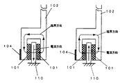
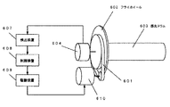
図8は感光ドラム駆動制御機構の従来例を示す図である。同図では、感光ドラムとフライホイールとが剛接合されており、フライホイールと駆動モータとはベルト減速機構を経由して接続されている。
駆動モータ610の回転力により、ベルト減速機構601を経由してフライホイール602が回転し、これに剛的に接合された感光ドラム603が回転する。そしてフライホイール602と同軸上にあるエンコーダ604も同じ回転数で回転する。これにより、感光ドラム603の回転角に応じた数だけパルスがエンコーダ604から出力され、検出装置607では、このパルス数を計数することによりドラム回転角を検出することができる。そして、制御装置608ではドラム回転角と目標回転角の偏差に応じた操作量を算出し、駆動装置609にてこの操作量に相当する電流を駆動モータ610に流すための印加電圧を発生する。駆動モータ610では印加電圧の変化により、感光ドラム軸の回転を一定に保っている。
As image quality increases in image forming apparatuses, color misregistration and banding have become more conspicuous than before when printing resolution is increased. Color misregistration is a phenomenon in which the printing position of each color shifts on the paper surface during color printing, and one of the causes is thought to be the mechanical eccentricity of the photosensitive drum. A method for improving the accuracy by using an advanced processing technique is known. Banding is a shade pattern in the sub-scanning direction seen on the printed paper, and one of the causes is considered to be uneven rotation of the photosensitive drum in a frequency band with high visual sensitivity. As a mechanical measure, there is known a method of removing a shading pattern in the sub-scanning direction by attaching a heavy flywheel to the photosensitive drum shaft to increase the inertia.
With regard to color misregistration, the demand for color misregistration between the photosensitive drums has become more and more severe as the tandem color image forming apparatus in which a plurality of photoconductors are arranged in series, and measures to prevent such color misregistration have been made. As one of the means, it is considered that highly accurate positioning control is necessary.
FIG. 8 is a diagram showing a conventional example of a photosensitive drum drive control mechanism. In the figure, the photosensitive drum and the flywheel are rigidly joined, and the flywheel and the drive motor are connected via a belt reduction mechanism.
The flywheel 602 rotates via the
図9は感光ドラム駆動制御機構の他の従来例を示す図である。同図では、感光ドラムとフライホイールとが剛接合されており、フライホイールと駆動モータとを減速機構なしに直接回転駆動している。
駆動モータ610の回転力により、直接フライホイール602が回転し、これに剛的に接合された感光ドラム603が回転する。そしてフライホイール602と同軸上にあるエンコーダ604も同じ回転数で回転する。これにより、感光ドラム603の回転角に応じた数だけパルスがエンコーダ604から出力され、検出装置607では、このパルス数を計数することによりドラム回転角を検出することができる。そして、制御装置608ではドラム回転角と目標回転角の偏差に応じた操作量を算出し、駆動装置609にて、この操作量に相当する電流を駆動モータ610に流すための印加電圧を発生する。駆動モータ610では印加電圧の変化により、感光ドラム軸の回転を一定に保っている。
さらに、他の従来例として、感光ドラムの駆動モータとは別に、感光ドラムの回転角変位、速度、加速度に応じて回転時の負荷を調整する感光ドラムの回転軸と平行な駆動軸を有する補助駆動モータを備えた回転制御方法もある(例えば特許文献1)。
The flywheel 602 directly rotates by the rotational force of the
Further, as another conventional example, in addition to the photosensitive drum drive motor, an auxiliary having a drive shaft parallel to the rotational axis of the photosensitive drum that adjusts the load during rotation according to the rotational angular displacement, speed, and acceleration of the photosensitive drum. There is also a rotation control method provided with a drive motor (for example, Patent Document 1).
しかしながら、図8のような構成では、減速機構として歯車やタイミングベルト等を介しているために、バンディング要因となる歯の噛合い周波数が問題となる。また、図9のような構成では、減速機構はないものの、高トルクを必要とするために、大口径のダイレクトドライブモータが必要となり、消費電力が増大して駆動回路が大型化してしまうという問題がある。更に特許文献1の技術では、補助駆動モータを必要とし、装置の大型化、製品コストの上昇という問題もある。
本発明は、上述した実情を考慮してなされたものであって、感光体ドラムが接続されたフライホイールの回転制御を行なうことにより、色ズレやバンディングが発生し難い画像形成装置を提供することを目的とする。
However, in the configuration as shown in FIG. 8, the gear meshing frequency that becomes a banding factor becomes a problem because a gear, a timing belt, and the like are provided as a speed reduction mechanism. Further, in the configuration as shown in FIG. 9, although there is no speed reduction mechanism, a high-torque direct drive motor is required because a high torque is required, resulting in a problem that power consumption increases and the drive circuit becomes large. There is. Furthermore, the technique of
The present invention has been made in consideration of the above-described circumstances, and provides an image forming apparatus that hardly causes color misregistration or banding by performing rotation control of a flywheel to which a photosensitive drum is connected. With the goal.
上記の課題を解決するために、請求項1に記載の画像形成装置は、定速での回転制御を必要とする慣性体を有する画像形成装置において、前記慣性体の軸方向端部側に慣性体と同軸状に剛接合したフライホイールと、前記フライホイール外周部に設けられてフライホイールを駆動する回転推進部と、該回転推進部の駆動力により前記慣性体を回転および回転制御する制御装置と、を備えたことを特徴とする。
また、請求項2は、請求項1記載の画像形成装置において、前記回転推進部は、磁力を用いて駆動力を得るようにしたことを特徴とする。
また、請求項3は、請求項1または2記載の画像形成装置において、前記フライホイールの外周部分に回転角検出用のスケールを設け、該スケールを読み取る位置センサにより回転角度を検出することを特徴とする。
また、請求項4は、請求項3記載の画像形成装置において、前記センサを回転軸をはさんで対向する位置に2つ配置したことを特徴とする。
また、請求項5は、請求項1、2または3記載の画像形成装置において、センサ出力を補正するための補正用データを記憶した補正用メモリを設け、前記センサ出力を補正して回転角度を検出するようにしたことを特徴とする。
In order to solve the above-described problems, an image forming apparatus according to
According to a second aspect of the present invention, in the image forming apparatus according to the first aspect, the rotation propulsion unit obtains a driving force using a magnetic force.
According to a third aspect of the present invention, in the image forming apparatus according to the first or second aspect, a scale for detecting a rotation angle is provided on an outer peripheral portion of the flywheel, and the rotation angle is detected by a position sensor that reads the scale. And
According to a fourth aspect of the present invention, in the image forming apparatus according to the third aspect of the present invention, two sensors are arranged at positions facing each other across the rotation axis.
According to a fifth aspect of the present invention, in the image forming apparatus according to the first, second, or third aspect, a correction memory storing correction data for correcting the sensor output is provided, and the rotation angle is adjusted by correcting the sensor output. It is characterized by being detected.
本発明によれば、慣性体とフライホイールが剛接合されているので、捩りによる機構固有の共振周波数を高くすることができ、制御帯域を高めることができる。このため、電子写真式カラープリンタ等に用いた場合には、色ずれ低減は勿論、バンディングの低減にも効果がある。また、駆動方式がダイレクトドライブでありながら、駆動部が回転中心から遠いため、回転軸の高トルク低速回転に適しており、要求される駆動部の駆動力も少なくて済み、より低い消費電力で回転および回転制御が可能となる。
また、大径フライホイールの外周部分に角度検出器を設けることにより、容易に高精度、高分解能な角度検出が可能となる。
また、フライホイールの外周部分に対向して2つの角度検出器を設けることにより、スケール誤差を低減して角度検出の精度を上げることができる。
さらに、組み付け時に高精度エンコーダで計測した補正用データを用いて回転制御を行うので、フライホイールの外周部分に1つの角度検出器を設けるのみで、スケール誤差を低減することができる。
According to the present invention, since the inertial body and the flywheel are rigidly joined, the resonance frequency inherent to the mechanism due to torsion can be increased, and the control band can be increased. For this reason, when used in an electrophotographic color printer or the like, it is effective in reducing banding as well as color misregistration. In addition, although the drive system is direct drive, the drive unit is far from the center of rotation, making it suitable for high-torque low-speed rotation of the rotating shaft, requiring less drive force of the drive unit, and rotating with lower power consumption And rotation control becomes possible.
Further, by providing an angle detector on the outer peripheral portion of the large-diameter flywheel, it is possible to easily detect the angle with high accuracy and high resolution.
Further, by providing two angle detectors facing the outer peripheral portion of the flywheel, the scale error can be reduced and the angle detection accuracy can be increased.
Furthermore, since rotation control is performed using correction data measured by a high-precision encoder at the time of assembly, the scale error can be reduced only by providing one angle detector on the outer peripheral portion of the flywheel.
以下、図面を参照して、本発明の実施形態を詳細に説明する。
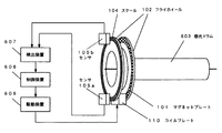
図1は、本発明の画像形成装置に係かる感光ドラム駆動機構の構成を示す図である。
図1では、減速機構なしに感光ドラムを高トルク低速回転させるために、感光ドラム(慣性体)の軸方向端部に取り付けられた大径フライホイール102の外周部分を直接駆動するように、外周部分に回転駆動力を発生する直動モータ(回転推進部)を設ける構成となっている。これにより、駆動部が回転中心から離れているため、大きなトルクを少ない力で発生させることができ、かつ低速回転を得られ易い。
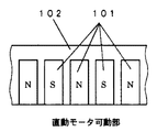
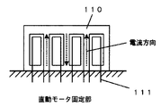
なお、直動モータは図3および図4に示すようにコイルプレートとマグネットプレートで構成される。図3は、フライホイール102の外周部分に形成されたマグネットプレート101を説明するための図である。また、図4は、可動部側のコイルプレート110の構成を示す図である。マグネットプレート101には極性が互い違いになるように磁石を取り付けておき、また、固定部側のコイルプレート110内部には、互い違いの方向にコイル111を巻いておき、このコイルに対して適切なタイミングで電流を流すことで、フレミングの左手の法則により直動モータが駆動する。
Hereinafter, embodiments of the present invention will be described in detail with reference to the drawings.
FIG. 1 is a diagram showing a configuration of a photosensitive drum driving mechanism according to the image forming apparatus of the present invention.
In FIG. 1, in order to rotate the photosensitive drum at high torque and low speed without a speed reduction mechanism, the outer peripheral portion of the large-
The linear motor is composed of a coil plate and a magnet plate as shown in FIGS. FIG. 3 is a view for explaining the
図5は、フライホイール102の外周部の断面図である。フライホイール102の二股に分かれた外周部のそれぞれの内側には直動モータの磁極を形成するマグネットプレート101が全外周に設けてあり、2つのマグネットプレート101の隙間にはコイルプレート110が極わずかなギャップを保って位置するように、フライホイール102とは独立に固定して設置されている。左側の図のように、コイルプレート110の一つのコイルに下向きの電流が流れると、コイルの右側にN極が出来るように破線矢印の方向に磁力線が発生する。したがって、このようなときにコイルの右側にメグネットプレート101を構成するS極が近づくと吸引され、反対にN極が離れようとすると反発し回転力を生じることになる。このようにしてコイルプレート110と、フライホイール102に設けたマグネットプレート101とで直動モータを形成している。
ところで、感光ドラム603の回転速度を一定に保つ位置制御を行うには、ドラムの回転角を知る必要がある。本発明では、大径フライホイール102の外周部分にはスケール104が設けてあり、光センサ105aおよび105bを設けることにより、光学的にスケール104をセンスして、感光ドラム603の回転角を検出するようにしている。スケール104とセンサ105の取り付け位置が回転中心(回転軸)から離れているため、外周部の線速が速くなることから高精度高分解能を容易に得ることができる。また回転軸に対して対象となる位置にそれぞれセンサ105を配置することにより、センサの検出誤差を打ち消して検出精度を高めている。
フライホイール102の外周部に取り付けるスケール104としては、磁気の影響を受けない光学式エンコーダが適している。また光学式においても透過式と反射式があるが、いずれも実装可能である。透過式は、コードホイール(=回転式スケール)外周部に形成された可動スリットと、センサ側の固定スリットとの間の窓を光が通過する光量を検出する方法であり、反射式はスケールの反射係数を交互に変えることにより、投光した光の反射する光量を検出する方法である。
FIG. 5 is a cross-sectional view of the outer peripheral portion of the
Incidentally, in order to perform position control for keeping the rotational speed of the photosensitive drum 603 constant, it is necessary to know the rotation angle of the drum. In the present invention, a
As the
次に、回転制御の動作を説明する。コイルプレート110とマグネットプレート101で構成される直動モータの駆動力によりフライホイール102が回転し、これに剛的に接合された感光ドラム603が回転する。そしてフライホイール102の外周上にあるエンコーダ用スケール104も感光ドラム603と同じ回転数で回転する。このスケール104を2つのセンサ105a、105bで読み取ることで、感光ドラム603の回転角を精度よく知ることができる。感光ドラムの回転角に応じた数だけパルスがセンサ105から出力されるため、検出装置607では、このパルス数を計数することによりドラム回転角を検出することができる。このとき、フライホイール102の外周部分に対向させて2つのセンサ(105a、105b)を設けることにより、フライホイール102外周上に設けられたスケール104の組み付け誤差やスケール精度に対して2つのセンサ出力誤差が相殺し合うため、精度良く回転角度を検出することができる。そして、制御装置608ではドラム回転角と目標回転角の偏差に応じた操作量を算出し、駆動装置609にて、この操作量に相当する電流を直動モータのコイルに流すための印加電圧を発生する。直動モータでは印加電圧の変化により、大径フライホイール102の回転を制御して、剛接合された感光ドラム102の回転を一定に保つようにしている。
なお、DCモータではトルクは電流に比例することから、本発明では操作量としてモータのコイルに流れる電流I(s)を用いている。駆動装置609内部では、この電流I(s)が指令電流(=制御装置608からの出力)に従って流れるように、モータへ印加する電圧E(s)を発生させる。参考として、DCモータにおける印加電圧E(s)から電流I(s)までの伝達関数を示すと次のようになる。
I(s)=(E(s)−Kω(s))/(sL+R)
ここで、Kは誘起電圧定数、ω(s)は電機子(ロータ)角速度で、sはラプラス演算子、Lは電機子インダクタンス、Rは電機子抵抗である。直動モータは円筒状の回転式モータを直線状に展開した構造と考えることができるので、駆動方法は回転式モータと同様であり、制御方法も従来技術を適用できる。
Next, the rotation control operation will be described. The
In the DC motor, since the torque is proportional to the current, the present invention uses the current I (s) flowing through the motor coil as the operation amount. Inside the
I (s) = (E (s) −Kω (s)) / (sL + R)
Here, K is an induced voltage constant, ω (s) is an armature (rotor) angular velocity, s is a Laplace operator, L is an armature inductance, and R is an armature resistance. Since the linear motor can be considered as a structure in which a cylindrical rotary motor is linearly developed, the driving method is the same as that of the rotary motor, and the conventional technique can be applied to the control method.
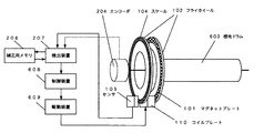
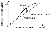
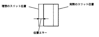
図2は、本発明の画像形成装置に係かる他の実施例を示す感光ドラム駆動機構の構成図である。本実施例では、センサ出力を補正するための補正用メモリ206を検出装置207に備えることにより、センサ105のみで回転角を高精度に検出できるようになっている。すなわち、検出装置207では図6に示すように、センサ105から得られる回転角(実線)を、補正用メモリ206から読み出した位置エラーで補正し、この値を制御装置608で読み取ることにより、高精度エンコーダ204で読み取る場合とほぼ同等の位置精度で回転角を読み取ることができる。ここでいう位置エラーとは、図7に示すように、感光ドラム603が実際に回転した角度(=高精度エンコーダ204から得られる回転角度)とセンサ105の出力パルス数から求められる回転角度との差である。
このことにより、スケール自身の精度誤差に関しても、予め組み付け時に高精度エンコーダ204を用いて計測しておき、この計測値を補正用メモリ206に記憶することにより、高精度エンコーダ204を取り外した状態(出荷時および通常使用時)でも補正用メモリ206に記憶された補正値を用いてセンサ105のみで精度よく回転角を検出することができる。
なお、以上の実施例では慣性体として感光ドラムを例に説明してきたが、転写ローラ、転写ベルト駆動ローラ等の回転を制御する必要がある慣性体にも適用できる。
FIG. 2 is a configuration diagram of a photosensitive drum driving mechanism showing another embodiment according to the image forming apparatus of the present invention. In the present embodiment, the correction device 206 for correcting the sensor output is provided in the
As a result, the accuracy error of the scale itself is also measured in advance using the high-precision encoder 204 at the time of assembly, and the measured value is stored in the correction memory 206, whereby the high-precision encoder 204 is removed ( Even at the time of shipment and normal use), the rotation angle can be detected with high accuracy only by the
In the above embodiments, the photosensitive drum has been described as an example of the inertial body. However, the present invention can also be applied to an inertial body that needs to control the rotation of a transfer roller, a transfer belt drive roller, or the like.
101 マグネットプレート(直動モータ可動側)、102 フライホイール、104 スケール、105 センサ、110 コイルプレート(直動モータ固定側)、111 コイル、204 ロータリエンコーダ、206 補正用メモリ、207 検出装置、601 ベルト減速機構、602 フライホイール、603 感光ドラム、604 ロータリエンコーダ、607 検出装置、608 制御装置、609 駆動装置、610 駆動モータ
DESCRIPTION OF
Claims (5)
5. The image forming apparatus according to claim 1, further comprising a correction memory that stores correction data for correcting the sensor output, and a controller that corrects the sensor output and detects a rotation angle. An image forming apparatus.
Priority Applications (1)
| Application Number | Priority Date | Filing Date | Title |
|---|---|---|---|
| JP2004110044A JP2005292632A (en) | 2004-04-02 | 2004-04-02 | Image forming apparatus |
Applications Claiming Priority (1)
| Application Number | Priority Date | Filing Date | Title |
|---|---|---|---|
| JP2004110044A JP2005292632A (en) | 2004-04-02 | 2004-04-02 | Image forming apparatus |
Publications (1)
| Publication Number | Publication Date |
|---|---|
| JP2005292632A true JP2005292632A (en) | 2005-10-20 |
Family
ID=35325594
Family Applications (1)
| Application Number | Title | Priority Date | Filing Date |
|---|---|---|---|
| JP2004110044A Pending JP2005292632A (en) | 2004-04-02 | 2004-04-02 | Image forming apparatus |
Country Status (1)
| Country | Link |
|---|---|
| JP (1) | JP2005292632A (en) |
Cited By (1)
| Publication number | Priority date | Publication date | Assignee | Title |
|---|---|---|---|---|
| JP2009134144A (en) * | 2007-11-30 | 2009-06-18 | Ricoh Co Ltd | Image forming apparatus |
-
2004
- 2004-04-02 JP JP2004110044A patent/JP2005292632A/en active Pending
Cited By (1)
| Publication number | Priority date | Publication date | Assignee | Title |
|---|---|---|---|---|
| JP2009134144A (en) * | 2007-11-30 | 2009-06-18 | Ricoh Co Ltd | Image forming apparatus |
Similar Documents
| Publication | Publication Date | Title |
|---|---|---|
| US8849134B2 (en) | Image forming apparatus having banding correction function | |
| JP2012014055A5 (en) | ||
| JP4312570B2 (en) | Rotating body drive control method and apparatus, image forming apparatus, process cartridge, program, and recording medium | |
| JPH09175687A (en) | Belt conveyor | |
| JP2000162941A (en) | Image forming device | |
| CN102236288A (en) | Image forming apparatus | |
| JP5102518B2 (en) | Image forming apparatus | |
| US9389546B2 (en) | Image forming apparatus with intermediate toner transfer medium, control method therefor, and storage medium storing control program therefor | |
| JP2002139112A (en) | Endless belt drive and image forming apparatus | |
| JP5509778B2 (en) | Belt conveying device and image forming apparatus | |
| JP5203823B2 (en) | Image forming apparatus, method for controlling image forming apparatus, program, and storage medium | |
| JP2005292632A (en) | Image forming apparatus | |
| JP2006058364A (en) | Image forming apparatus | |
| JP2009183113A (en) | Motor, rotation control device, and rotation detection circuit | |
| JP4663282B2 (en) | Belt conveying apparatus and image forming apparatus | |
| JP4339079B2 (en) | Transfer belt speed control method, transfer belt speed control apparatus, and image forming apparatus using the same | |
| US20050129427A1 (en) | Rotary member driving mechanism, and image forming apparatus employing this mechanism | |
| JP2007078538A (en) | Motor, rotation control device, and rotation detection circuit | |
| JP6569635B2 (en) | Motor control device and image forming apparatus | |
| JP2005309309A (en) | Drive control device for color image forming apparatus | |
| JP4564314B2 (en) | Image forming apparatus | |
| JP5173851B2 (en) | Image forming apparatus | |
| JP2006084669A (en) | Photoconductor drive control in color image forming apparatus | |
| JP5398431B2 (en) | Image forming apparatus | |
| JP2008176149A (en) | Image forming apparatus |