JP5203823B2 - Image forming apparatus, method for controlling image forming apparatus, program, and storage medium - Google Patents
Image forming apparatus, method for controlling image forming apparatus, program, and storage medium Download PDFInfo
- Publication number
- JP5203823B2 JP5203823B2 JP2008178369A JP2008178369A JP5203823B2 JP 5203823 B2 JP5203823 B2 JP 5203823B2 JP 2008178369 A JP2008178369 A JP 2008178369A JP 2008178369 A JP2008178369 A JP 2008178369A JP 5203823 B2 JP5203823 B2 JP 5203823B2
- Authority
- JP
- Japan
- Prior art keywords
- speed
- torque
- motor
- correction data
- correcting
- Prior art date
- Legal status (The legal status is an assumption and is not a legal conclusion. Google has not performed a legal analysis and makes no representation as to the accuracy of the status listed.)
- Expired - Fee Related
Links
Images


Description
本発明は、画像形成技術に関する。 The present invention relates to an image forming technique.
従来のカラー画像を形成するための画像形成装置の概略構成を図15(a)、(b)に示す。図15(a)は画像形成部の機構的な構成を示し、図15(b)は画像形成装置の概略の制御構成を示す。画像形成部は、図15(a)に示すように、例えば、Y(黄)、M(マゼンダ)、C(シアン)、K(黒)の4色の画像をそれぞれ電子写真方式により形成することが可能な4組の画像形成ユニットから構成されている。例えば、Y(黄)の画像を形成する画像形成ユニットは、感光ドラム105、現像器106、クリーナ107、帯電器108、一次転写ローラ109、レーザ光学系110から成る。各画像形成ユニットは、対応する色の画像を中間転写ベルト101上にそれぞれ形成する。
FIGS. 15A and 15B show a schematic configuration of an image forming apparatus for forming a conventional color image. FIG. 15A shows a mechanical configuration of the image forming unit, and FIG. 15B shows a schematic control configuration of the image forming apparatus. As shown in FIG. 15A, the image forming unit forms, for example, four color images of Y (yellow), M (magenta), C (cyan), and K (black), respectively, by an electrophotographic method. It is composed of four sets of image forming units capable of. For example, an image forming unit that forms a Y (yellow) image includes a
画像形成部の画像形成動作は、図15(b)に示すシステムコントローラ120によって制御される。画像読取装置121または画像処理装置122よりカラー画像データが供給されると、これがシステムコントローラ120を介して各色の画像形成ユニットに供給される。各画像形成ユニットにおける感光ドラムには、光の照射によって電気的特性が変化する光導電層が形成されている。各感光ドラムは、画像形成動作中に定速回転を行い、以下に示す処理(1)〜(5)が各画像形成ユニットにおいて行われる。以下の説明では、Y(黄)の画像を形成する画像形成ユニット(Y用画像形成ユニット)を例に説明する。
The image forming operation of the image forming unit is controlled by the
(1)帯電:帯電器108が感光ドラム105の光半導体層を均一に帯電する。
(1) Charging: The
(2)レーザ露光:レーザ光学系110が、感光ドラム105に向けてレーザ光を照射し、感光ドラム105上に静電潜像を形成する。
(2) Laser exposure: The laser
(3)現像:現像器106が、感光ドラム105上の静電潜像にトナーを付着する。
(3) Development: The developing
(4)一次転写:一次転写ローラ109が、感光ドラム105上のトナー像を中間転写ベルト101に転写する。
(4) Primary transfer: The
(5)クリーニング:中間転写ベルト101に転写しきれずに感光ドラム105上に残ったトナーをクリーナ107がクリーニングする。
(5) Cleaning: The
次に、処理(6)、(7)によって、中間転写ベルト101に転写されたトナー像を記録紙へ転写し定着する。
Next, by processing (6) and (7), the toner image transferred to the
(6)二次転写:二次転写器111が、中間転写ベルト101上のトナー像を記録紙に転写する。
(6) Secondary transfer: The
(7)定着:定着器112が記録紙に対して加熱及び加圧を行い、トナーを記録紙上に定着させ、記録紙を画像形成部の外に排出する。
(7) Fixing: The
上述したように、中間転写ベルト101上には、各画像形成ユニットにてそれぞれ形成されたトナー像がタイミングを合わせて順に転写され、各トナー像が重なり合うようになっている。しかし、中間転写ベルト101の移動速度に変動が生じると、中間転写ベルト101に転写される各色のトナー像の転写位置が、本来の転写位置からずれてしまい、色ずれ(1次転写位置のずれ)や濃度ムラ等の画質の劣化が発生する。
As described above, the toner images formed by the respective image forming units are sequentially transferred onto the
ここで、図15(a)に示すように、中間転写ベルト101は、駆動ローラ104の回転駆動に応じて図中矢印Aの方向に周回駆動され、駆動ローラ104には、駆動モータ(ステッピングモータ102)の駆動力が駆動ギア103を介して伝達される。
Here, as shown in FIG. 15A, the
次に、中間転写ベルト101の搬送速度について以下に説明する。
Next, the conveyance speed of the
駆動ローラ104の半径をr、中間転写ベルト101の厚さを2d0とし、中間転写ベルト101の厚さ方向の中心までの厚みをd0とする。駆動ローラ104の角速度をωとすると、中間転写ベルト101の搬送速度Vbは式(1)で求めることができる。
The radius of the
Vb=(r+d0)×ω ・・・(1)
中間転写ベルト101の搬送速度Vbを変動させる代表的な要因には、例えば、駆動ローラ104の偏心成分Δrと、中間転写ベルト101の厚みムラΔd(シームレスベルト製造時に発生)が挙げられる。また、駆動ギア103の偏心成分による駆動ローラ104の角速度変動分Δωも搬送速度Vbの変動要因として考えられる。こうした変動要因を考慮すると、搬送速度Vbは式(2)で表される。
Vb = (r + d0) × ω (1)
Typical factors that cause the conveyance speed Vb of the
Vb=(r+Δr+Δd)×(ω+Δω)
=rω+Δrω+Δdω+(r+Δr+Δd)×Δω ・・・(2)
したがって、速度変動成分ΔVb(=Vb−rω)は式(3)で表される。
Vb = (r + Δr + Δd) × (ω + Δω)
= Rω + Δrω + Δdω + (r + Δr + Δd) × Δω (2)
Therefore, the speed fluctuation component ΔVb (= Vb−rω) is expressed by Expression (3).
ΔVb=Δrω+Δdω+Δω×(r+Δr+Δd)
=ΔVr+ΔVd+ΔVω ・・・(3)
ただし、ΔVr=Δrω、ΔVd=Δdω、ΔVω=Δω×(r+Δr+Δd)とする。
ΔVb = Δrω + Δdω + Δω × (r + Δr + Δd)
= ΔVr + ΔVd + ΔVω (3)
However, ΔVr = Δrω, ΔVd = Δdω, and ΔVω = Δω × (r + Δr + Δd).
ここで、ΔVrは、駆動ローラ104の偏心成分Δrに起因する速度変動分、ΔVdは、中間転写ベルト101の厚みムラΔdに起因する速度変動分、ΔVωは、駆動ローラ104の角速度変動分Δωに起因する速度変動分である。
Here, ΔVr is the speed fluctuation due to the eccentric component Δr of the
駆動ローラ104の中間転写ベルト101との上方接点位置P0とY(黄)の感光ドラム105の転写点P1との間の距離をD1とする。他の各感光ドラムの転写点間(P1P2間、P2P3間、P3P4間)の距離を距離D2、D3、D4とする。駆動ローラ104の周長が距離D1に一致し、且つ、D2〜D4の合算値が、駆動ローラ104の周長の整数倍の長さとなるように、画像形成部の機械的構造を構成する。これにより、(3)式の第一項である駆動ローラ104の偏心成分Δrに起因する速度変動分(ΔVr)が一次転写時における色ずれへ及ぼす影響を低減することが可能である。
The distance between the upper contact position P0 of the
(3)式の第ニ項である中間転写ベルト101の厚みムラΔdに起因する速度変動分(ΔVd)に関しては、中間転写ベルト101に所定パターンの画像を所定間隔で複数形成する。その中間転写ベルト101に形成された個々の所定パターンを、中間転写ベルト101の周回ルートの1箇所で検出し、その各検出タイミングの時間差に基づいて中間転写ベルト101の厚みムラΔdを検知する。これによって駆動ローラ104の回転速度を制御する手法、または各感光ドラムにおける光学系書き込み位置を制御する手法が提案されている(特許文献1)。
With respect to the speed fluctuation (ΔVd) caused by the thickness unevenness Δd of the
(3)式の第三項である駆動ローラ104の角速度変動分Δωに起因する速度変動分(ΔVω)に関しては駆動ローラ104の軸上にエンコーダを設置し、エンコーダの検出信号に基づいて駆動ローラ104の駆動周波数を算出する。この駆動周波数を利用して駆動ローラ104の角速度変動を補正する手法が一般的に実施されている。
Regarding the speed fluctuation (ΔVω) caused by the angular speed fluctuation Δω of the
(3)式の第一項、および、第三項に関する駆動ローラ104の偏心成分Δrに起因する速度変動分(ΔVr)及び駆動ローラ104の角速度変動分Δωに起因する速度変動分(ΔVω)の影響低減に関しては、以下の方法が提案されている。駆動伝達系の機械的構造を調整可能とし、かつ、駆動対象負荷の絶対角度・回転速度を検出可能として、それらの値を元に駆動側では各負荷駆動の位相を合わせて制御を行う。これにより、色ずれ、濃度ムラを抑制する方法が提案されている(特許文献2)。 In the first term and the third term of the equation (3), the speed fluctuation due to the eccentric component Δr of the drive roller 104 (ΔVr) and the speed fluctuation due to the angular speed fluctuation Δω of the drive roller 104 (ΔVω). The following methods have been proposed for effect reduction. The mechanical structure of the drive transmission system can be adjusted, and the absolute angle and rotational speed of the load to be driven can be detected, and control is performed on the drive side in accordance with the phase of each load drive based on these values. Thus, a method for suppressing color misregistration and density unevenness has been proposed (Patent Document 2).
以上説明した速度変動成分は機械構成要素(偏心・厚み・ローラ径)によるものである。通常、モータによる駆動装置における速度変動要素としては、さらに、画像形成動作中に発生する外乱要因によるトルク変化による速度変動要素が加わることになる。 The speed fluctuation component described above is due to machine components (eccentricity, thickness, roller diameter). Normally, a speed fluctuation element due to a torque change due to a disturbance factor generated during an image forming operation is further added as a speed fluctuation element in a motor drive device.
これらの負荷変動を誘発する外乱としては、複写媒体である用紙の通過、および、中間転写ベルト101用のクリーナ機構の脱着動作などが上げられる。これによるトルク変動は結果として中間転写ベルト101の搬送速度Vbに瞬間的に速度変動が生じ、その結果、色ずれ、濃度ムラが生じることになる。
Examples of disturbances that induce these load fluctuations include the passage of a sheet as a copying medium and the removal / attachment operation of the cleaner mechanism for the
次に、駆動側となるパルスモータ(ステッピングモータ)は回転子位置を検出して制御回路にフィードバックする必要が無いオープンループ制御で駆動することが可能なモータである。その指令値は入力パルスのパルス数、周期により位置、および速度制御が可能である。入力パルスに同期する動作はパルス入力毎に固定子側の各相(2相ステッピングモータの場合A、A*、B、B*)に流れる電流を順次切換ていくことで回転磁界が生成される。 Next, a pulse motor (stepping motor) on the drive side is a motor that can be driven by open-loop control without the need to detect the rotor position and feed it back to the control circuit. The command value can be controlled in position and speed according to the number and cycle of input pulses. In the operation synchronized with the input pulse, a rotating magnetic field is generated by sequentially switching the current flowing through each phase on the stator side (A, A *, B, B * in the case of a two-phase stepping motor) for each pulse input. .
図13はステッピングモータの駆動回路構成を例示した図である。この回路において、A、A*、B、B*の各相が順次励磁され、巻線電流が所定の電流値となるようにオン・オフ比率を制御することで定電流制御駆動が行われる。オン・オフ比率の制御にはPWM制御が用いられる。これにより、巻線電流の大きさに比例した回転磁界が発生する。このような制御を適用することでステッピングモータは、指令入力信号のパルス数を位置指令、パルス周期を速度指令として駆動される。このステッピングモータは、その構造上、永久磁石同期モータの分類に属するが、この永久磁石同期モータの発生するトルクとしては下記のようになる。 FIG. 13 is a diagram illustrating a drive circuit configuration of the stepping motor. In this circuit, each phase of A, A *, B, and B * is sequentially excited, and constant current control driving is performed by controlling the on / off ratio so that the winding current has a predetermined current value. PWM control is used to control the on / off ratio. Thereby, a rotating magnetic field proportional to the magnitude of the winding current is generated. By applying such control, the stepping motor is driven with the number of pulses of the command input signal as a position command and the pulse cycle as a speed command. This stepping motor belongs to the category of permanent magnet synchronous motors due to its structure, but the torque generated by this permanent magnet synchronous motor is as follows.
トルク=永久磁石の磁束の大きさ×巻線電流の大きさ×sin(位相差φd)・・・(4)
位相差φd:永久磁石による磁束とモータ巻線電流による磁束とのなす角(=負荷角)
定電流制御により巻線電流が所定値に制御された場合、巻線電流により発生する磁束は固定値となる。そのため、図14のようにモータ軸に接続された負荷により印加される負荷トルクに応じて、位相差φd、つまり、負荷角がモータの駆動により自動調整されて、モータトルクが負荷トルクと釣り合う位置で回転することになる。これは設定した電流値で発生する最大トルク以上の負荷が印加された場合には、モータは同期駆動ができない状態、一般に『脱調』と呼ばれる状態に陥り、駆動不能の状態になることを意味する。
Torque = Magnetic flux of permanent magnet x Winding current x sin (phase difference φd) (4)
Phase difference φd: Angle between the magnetic flux generated by the permanent magnet and the magnetic flux generated by the motor winding current (= load angle)
When the winding current is controlled to a predetermined value by the constant current control, the magnetic flux generated by the winding current becomes a fixed value. Therefore, as shown in FIG. 14, the phase difference φd, that is, the load angle is automatically adjusted by driving the motor according to the load torque applied by the load connected to the motor shaft, and the motor torque is balanced with the load torque. Will rotate. This means that if a load greater than the maximum torque generated at the set current value is applied, the motor will not be able to drive synchronously, generally called a “step-out” state, and will be unable to drive. To do.
このように、ステッピングモータは、位置検出手段が無くてもパルス数による位置決め駆動、パルス周期による速度制御が行えると云った利点を備えている。反面、取り付ける製品に必要な負荷トルクに対して、脱調をしないようにトルクマージンを設けてステッピングモータの発生できるトルクを設計する必要がある。 As described above, the stepping motor has an advantage that positioning driving based on the number of pulses and speed control based on the pulse period can be performed without the position detecting means. On the other hand, it is necessary to design a torque that can be generated by the stepping motor by providing a torque margin so as not to step out of the load torque required for the product to be attached.
また、前述したように、負荷の変化により釣り合い位置が変化する、つまり、速度変動が発生することになり、駆動負荷の速度変動につながることにもなる。トルクマージンを大きく採って動作させることは、負荷変動時の速度変動を抑制する利点を持ってはいるが、逆にトルク余りによる速度変動・振動・騒音の発生と云った問題をも生じさせてしまう等の欠点要素の方が多い。 Further, as described above, the balance position changes due to the change of the load, that is, the speed fluctuation occurs, which leads to the speed fluctuation of the driving load. While operating with a large torque margin has the advantage of suppressing speed fluctuations during load fluctuations, it also causes problems such as speed fluctuations, vibrations and noise caused by excess torque. There are more fault elements such as end.
これらの現状に対して、製品にステッピングモータが実装された状態でトルクを測定する方法として、巻線電流または、巻線電流とエンコーダ情報からトルクを測定する方法がある(例えば、特許文献3、特許文献4)。
As a method for measuring the torque in a state where the stepping motor is mounted on the product against these current situations, there is a method of measuring the torque from the winding current or the winding current and encoder information (for example,
また、負荷トルクの変動に対して脱調の回避や振動の低減を行うステッピングモータ制御装置として、エンコーダを用いることにより負荷トルクと関連があるロータとステータの位置関係から励磁タイミングを変化させるものがある。また、巻線電流値からロータとステータの位置関係を推定し励磁タイミングを変化させるものが実用化されている。また、巻線電流値とステッピングモータへの入力電流値との比率から巻線電流設定値を変更させるものが提案されている(特許文献5)。
しかしながら、上述した特許文献1は、駆動対象負荷(画像形成装置におけるベルト)の速度変動を検出する手段の提案が主な内容であり、速度変動に対するフィードバック制御については詳細な説明が成されていない。また、特許文献2に示される画像形成装置においては、駆動系の偏心・位相合わせを、伝達系の機械的構造・調整で行う提案のため、コスト高な構成とならざるを得ない。
However, the above-mentioned
また、特許文献2において駆動モータとしてパルスモータ(=ステッピングモータ)を使用する場合に、速度変動に対するフィードバック制御については明示されていない。
Further, in
更に、特許文献3乃至5では、トルクの測定法、エンコーダによる負荷トルクの変動に対して脱調の回避や振動の低減を行う構成が開示されているが、フィードバック制御については詳細な説明が成されていない。
Further,
本発明は、画像形成中の機械要素系の負荷変動、外乱による中間転写ベルトの搬送速度変動があっても良好な画質の画像を得ることが可能な画像形成装置の提供を目的とする。 SUMMARY OF THE INVENTION An object of the present invention is to provide an image forming apparatus capable of obtaining an image of good image quality even when there is a load fluctuation of a mechanical element system during image formation and a fluctuation in the conveyance speed of an intermediate transfer belt due to a disturbance.
上記の目的を達成する本発明にかかる画像形成装置は、パルスにより駆動するモータを制御するための制御手段を有する画像形成装置であって、前記制御手段は、
速度制御により前記モータを駆動するために生成された速度指令駆動パルスと、当該モータの速度を検出する検出手段により検出された検出速度情報とから、前記モータの速度偏差を算出する速度偏差算出手段と、
前記速度偏差を補正するための速度補正データを速度フィードフォワード制御指令として生成する速度補正データ生成手段と、
前記速度フィードフォワード制御指令により前記速度偏差を補正する速度偏差補正手段と、
前記モータを駆動するためにモータドライバに入力される電流値と、当該モータを駆動するために前記モータドライバに入力される速度指令駆動パルスとから、当該モータを駆動するためのトルクを算出するトルク算出手段と、
前記モータの回転により生じるトルクの変動を算出するトルク変動データ算出手段と、
前記トルクの変動を補正するためのトルク補正データをトルクフィードフォワード制御指令として生成するトルク補正データ生成手段と、
前記トルクフィードフォワード制御指令により前記トルクの変動を補正するトルク補正手段と、
前記速度フィードフォワード制御指令を用いて前記速度偏差補正手段によって前記速度偏差が補正され、前記トルクフィードフォワード制御指令を用いて前記トルク補正手段によって前記トルクの変動が補正された状態で、当該トルクフィードフォワード制御指令により前記電流値を補正するトルクフィードバック制御手段と、
を備えることを特徴とする。
An image forming apparatus according to the present invention that achieves the above object is an image forming apparatus having a control unit for controlling a motor driven by a pulse, wherein the control unit includes:
Speed deviation calculating means for calculating the speed deviation of the motor from speed command drive pulses generated for driving the motor by speed control and detected speed information detected by the detecting means for detecting the speed of the motor. When,
Speed correction data generating means for generating speed correction data for correcting the speed deviation as a speed feedforward control command;
A speed deviation correction means for correcting a more the speed deviation to the speed feed forward control command,
Torque for calculating the torque for driving the motor from the current value input to the motor driver for driving the motor and the speed command drive pulse input to the motor driver for driving the motor A calculation means;
Torque fluctuation data calculating means for calculating torque fluctuation caused by rotation of the motor;
Torque correction data generating means for generating torque correction data for correcting fluctuations in the torque as a torque feedforward control command;
A torque correcting means for correcting the variation of more the torque on the torque feedforward control command,
The speed feed the speed deviation by the speed deviation correction means using forward control command is corrected, in a state where variation of the torque is corrected by the torque correcting means using the torque feed forward control command, the torque feed torque feedback control means for correcting the more the current value in the forward control command,
It is characterized by providing.
あるいは、本発明にかかる画像形成装置は、パルスにより駆動するモータを制御するための制御手段を有する画像形成装置であって、当該制御手段が、
速度制御により前記モータを駆動するために生成された速度指令駆動パルスと、当該モータの速度を検出する検出手段により検出された検出速度情報とから、前記モータの速度偏差を算出する速度偏差算出手段と、
前記速度偏差を補正するための速度補正データを生成する速度補正データ生成手段と、
トナー像を形成するためのベルト上に予め定められた基準間隔で形成されている複数のパターン画像を、当該ベルトの搬送に従い、画像読取手段が読み取ったパターン画像の間隔と、前記基準間隔とから、当該ベルトの搬送の1周分の厚みムラによる速度偏差を算出する算出手段と、
前記算出手段により算出された前記ベルトの搬送の1周分の厚みムラによる速度偏差を補正するための厚みムラ補正データを生成する厚みムラ補正データ生成手段と、
前記速度補正データ生成手段により生成された前記速度補正データと、前記厚みムラ補正データ生成手段により生成された前記厚みムラ補正データとから、前記速度偏差を補正するための速度フィードフォワード制御指令を生成する速度フィードフォワード制御指令生成手段と、
前記速度フィードフォワード制御指令により前記速度偏差を補正する速度偏差補正手段と、
前記速度フィードフォワード制御指令を用いて前記速度偏差補正手段により前記速度偏差が補正された状態で、前記厚みムラ補正データにより、前記モータを駆動するためにモータドライバに入力される電流値を補正して、当該モータの駆動トルクをフィードバック制御するトルクフィードバック制御手段と、
を備えることを特徴とする。
Alternatively, the image forming apparatus according to the present invention is an image forming apparatus having a control unit for controlling a motor driven by a pulse, and the control unit includes:
Speed deviation calculating means for calculating the speed deviation of the motor from speed command drive pulses generated for driving the motor by speed control and detected speed information detected by the detecting means for detecting the speed of the motor. When,
Speed correction data generating means for generating speed correction data for correcting the speed deviation;
A plurality of pattern images are formed at predetermined reference intervals on a belt to form a toner image, in accordance with the conveyance of the belt, and spacing of the pattern image by the image reading unit has read, from the reference interval Calculating means for calculating a speed deviation due to thickness unevenness for one round of conveyance of the belt;
Thickness unevenness correction data generating means for generating thickness unevenness correction data for correcting a speed deviation due to thickness unevenness of one round of conveyance of the belt calculated by the calculating means;
Generates a speed feedforward control command for correcting the speed deviation from the speed correction data generated by the speed correction data generation means and the thickness unevenness correction data generated by the thickness unevenness correction data generation means. Speed feedforward control command generating means for performing,
A speed deviation correction means for correcting a more the speed deviation to the speed feed forward control command,
In a state where the speed deviation by the speed deviation correction means using said speed feedforward control command is corrected, the more thickness irregularity correction data, the correction value of the current input to the motor driver to drive the motor A torque feedback control means for feedback controlling the driving torque of the motor;
It is characterized by providing.
本発明によれば、画像形成中の機械要素系の負荷変動、外乱による中間転写ベルトの搬送速度変動があっても良好な画質の画像を得ることが可能になる。 According to the present invention, it is possible to obtain an image having a good image quality even when there is a load variation of the machine element system during image formation and a conveyance speed variation of the intermediate transfer belt due to a disturbance.
あるいは、本発明によれば、速度検出と負荷トルクの検出により、機械的な取り付け誤差、形状誤差等の要因による速度変動はステッピングモータの速度指令としてフィードフォワード制御することができる。また、定常的な負荷トルク変動要因はモータ電流値へのフィードフォワード制御により、速度変動要素を補正することができる。 Alternatively, according to the present invention, by speed detection and load torque detection, speed fluctuation due to factors such as mechanical attachment error and shape error can be feedforward controlled as a speed command of the stepping motor. The steady load torque fluctuation factor can be corrected for the speed fluctuation factor by feedforward control to the motor current value.
また、本発明によれば、突発的な負荷トルク変動要因に対して速度変化を検出することでモータ電流のフィードバック制御を行うこことで、トルク変動に対して安定した速度制御が可能となる。 Further, according to the present invention, the motor current feedback control is performed by detecting the speed change with respect to the sudden load torque fluctuation factor, and the speed control stable with respect to the torque fluctuation becomes possible.
以下、図面を参照して、本発明の好適な実施形態を例示的に詳しく説明する。ただし、この実施の形態に記載されている構成要素はあくまで例示であり、本発明の技術的範囲は、特許請求の範囲によって確定されるのであって、以下の個別の実施形態によって限定されるわけではない。 Hereinafter, exemplary embodiments of the present invention will be described in detail with reference to the drawings. However, the constituent elements described in this embodiment are merely examples, and the technical scope of the present invention is determined by the scope of claims, and is limited by the following individual embodiments. is not.
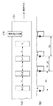
図1(a)、(b)は、実施形態にかかる画像形成装置の概略的な構成を示す図であり、図15(a)、(b)の構成要素と同様の部分においては、同一の参照番号を用いることにより、説明を省略する。 FIGS. 1A and 1B are diagrams illustrating a schematic configuration of an image forming apparatus according to the embodiment. The same components as those in FIGS. 15A and 15B are the same as those in FIG. Description is omitted by using reference numerals.
各感光ドラム(感光体)の回転軸周辺には、ドラムの回転位置・速度を検出するためのエンコーダ117(Y,M,C,K)と、エンコーダの基準位置を検出するためのホームポジションセンサ118(Y,M,C,K)と、が設けられている。 Encoder 117 (Y, M, C, K) for detecting the rotational position / speed of the drum and a home position sensor for detecting the reference position of the encoder are arranged around the rotating shaft of each photosensitive drum (photosensitive body). 118 (Y, M, C, K).
中間転写ベルト101の駆動ローラ104の回転軸周辺には、感光ドラムと同様にエンコーダ113が設置されている。エンコーダ113は、駆動ローラ104の回転位置情報と、速度情報(角速度)を検出することが可能である。
An
駆動ローラホームポジションセンサ114は、エンコーダ113と同様に駆動ローラ104の軸上に設置され、駆動ローラ104の基準位置を検出することにより、駆動ローラ104の1回転の回転周期のタイミングを検出する。
The drive roller
ベルトホームポジションセンサ115は、中間転写ベルト101上に設けられた検出用マークを検出する。画像読取センサ116は、中間転写ベルト101の面上に形成されたトナー像、または所定パターン画像を検出することが可能である。
The belt
図2は、本実施形態にかかる画像形成装置の制御ブロックを示す図である。画像形成装置はシステムコントローラ120によって統括的にコントロールされ、主に画像形成装置を構成する各ユニットの駆動、センサやエンコーダにより検出された情報の収集、収集した情報の解析の役割を主に担っている。システムコントローラ120の内部には、CPU201が搭載されている。CPU201は、システムコントローラ120に搭載されたROM202に格納されたプログラムによって、予め決められた画像形成シーケンスに関する様々なシーケンスを実行する。その際、一時的または恒久的に保存することが必要な書き換え可能なデータを格納するために、RAM203も搭載されている。
FIG. 2 is a diagram illustrating a control block of the image forming apparatus according to the present embodiment. The image forming apparatus is comprehensively controlled by the
ASIC301は、中間転写ベルト(ITB)101の位置・速度情報を検出して中間転写ベルト101を駆動するベルト系の制御と、感光ドラム105の位置・速度を検出して感光ドラム105駆動するドラム駆動系の制御とを行う。
The
(ベルト駆動系)
ASIC301はベルト駆動系の制御として、AD変換器302、位置・速度検出用カウンタ303、ベルト駆動ローラ位置・速度情報変換部306、指令値位置・速度情報変換部307を有する。AD変換器302は、中間転写ベルト(ITB)101の上方に設けられている画像読取センサ116により読み取られたアナログ出力信号をAD変換する。
(Belt drive system)
The
位置・速度検出用カウンタ303は、駆動ローラ104の回転軸の位置、回転速度を検出するためのエンコーダ113の出力信号をカウントする。ベルト駆動ローラ位置・速度情報変換部306は、位置・速度検出用カウンタ303での計数値を、中間転写ベルト101を駆動する駆動ローラ104の位置・速度情報に変換する。指令値位置・速度情報変換部307は、ステッピングモータ102bを駆動するための駆動パルスをカウントするカウンタ305と、カウンタ305での計数値を位置・速度情報に変換する。
The position /
(ドラム駆動系)
ASIC301はドラム駆動系の制御として、位置・速度検出用カウンタ310、カウンタ312、ドラム軸位置・速度情報変換部313、指令値位置・速度情報変換部314、入力電流検出部206a、AD変換器315、負荷角換算部316を有する。位置・速度検出用カウンタ310は、感光ドラム105のドラム駆動軸の位置・速度を検出するためのエンコーダ117の出力信号をカウントする。ドラム軸位置・速度情報変換部313は、位置・速度検出用カウンタ310の計数値を、位置・速度情報に変換する。カウンタ312は、ステッピングモータ102aの駆動パルス(指令値情報)をカウントする指令値位置・速度情報変換部314は、カウンタ312の計数値を位置・速度情報に変換する。入力電流検出部206aは、ステッピングモータ102aの駆動回路(モータドライバ205a)への入力電流を検出するAD変換器315は、入力電流検出部206aにより検出された値をAD変換する。負荷角換算部316は、指令値位置・速度情報変換部314の出力とAD変換器315の出力とに基づきステッピングモータの負荷角換算(位相角の算出)を行う。
(Drum drive system)
The
以上の2系統の構成により検出、変換された値はシステムコントローラ120に送信される。また、ASIC301は、ベルト駆動系及びドラム駆動系として、クロック生成器304、311をそれぞれ有する。クロック生成器304、311は、中間転写ベルト(ITB)101、および、感光ドラム105を回転駆動するためのステッピングモータ102a、ステッピングモータ102bを駆動するためのクロックを生成する。クロック生成器304、311は、CPU201により設定された値(速度指令、電流指令)に基づいてモータドライバ205b、モータドライバ205aに駆動クロックを出力する。これにより、モータドライバ205b、205aは駆動クロックの周波数に基づいてステッピングモータb、102aを駆動する。
The values detected and converted by the above two systems are transmitted to the
以上のような構成において、各ステッピングモータの速度制御、および、電流制御を説明する。 In the above configuration, the speed control and current control of each stepping motor will be described.
(ドラム駆動系の制御)
図2、図3を参照して、ASIC301によるドラム駆動系の制御を説明する。
(Drum drive system control)
The control of the drum drive system by the
(速度指令制御)
図3において、制御ブロック801は、ステッピングモータの速度指令を補正する速度指令制御ブロックを示す。CPU201は、速度偏差算出手段として機能する。CPU201は、速度制御によりステッピングモータを駆動するために生成された速度指令駆動パルスと、速度を検出する検出手段として機能するエンコーダ117により検出された検出速度情報と、に基づき速度偏差を算出する。CPU201は、速度指令駆動パルス350に基づき感光ドラム105を駆動するためのステッピングモータ102aを、予め設定された所定の駆動周波数Vtにより駆動するための制御を行う。カウンタ312によりカウントされた、ステッピングモータ102aの駆動パルス(指令値情報)は、指令値位置・速度情報変換部314により位置・速度情報に変換される。この変換結果は、速度指令駆動パルス350に対応する。速度指令駆動パルス350に基づきクロック生成器311は駆動クロックを生成し、モータドライバ205aは、駆動クロックの周波数に基づいてステッピングモータ102aを駆動する。
(Speed command control)
In FIG. 3, a control block 801 indicates a speed command control block for correcting the speed command of the stepping motor. The
位置・速度検出用カウンタ310は、感光ドラム105のドラム駆動軸の位置・速度を検出するためのエンコーダ117から出力されるパルス数(出力信号)をカウントする。位置・速度検出用カウンタ310はASIC301、もしくはCPU201のベースクロックに基づき動作し、エンコーダ117から出力されるパルス数(出力信号)を1パルスずつカウントするのに、十分に早い速度でカウントすることが可能である。
The position /
位置・速度検出用カウンタ310はエンコーダ分解能(1パルスあたりの角度deg/pls)に基づき出力信号のカウントを行う。このカウント値(計数値)に基づき、ドラム軸位置・速度情報変換部313は感光ドラム105の駆動軸の位置検出を行い、ベースクロックによる時間換算から速度検出を行う。位置・速度検出用カウンタ310の計数値は、ホームポジションセンサ118がエンコーダ117の基準位置(ホームポジション位置)を検出時にリセットされる。位置・速度検出用カウンタ310は、ホームポジション位置から位置・速度情報を生成するためのカウントを開始する。
The position /
ドラム軸位置・速度情報変換部313からの出力が感光ドラム105の駆動軸の検出位置情報、検出速度情報351となる。
The output from the drum shaft position / speed information conversion unit 313 becomes detection position information and
CPU201はドラム軸位置・速度情報変換部313から出力される検出速度情報351と、ステッピングモータ102aの速度の目標値である速度指令駆動パルス350との偏差を求める。CPU201は、この偏差に基づき、感光ドラム105の回転駆動の1周期分における駆動ギアの偏心成分を抽出した速度偏差プロファイル3011を生成する。速度偏差プロファイル3011が示す正弦波状のプロファイルは、感光ドラム105の1回転分の速度ムラを模式的に示している。
The
CPU201は、速度偏差プロファイル3011に対応する速度偏差データを納めた速度偏差データテーブルをRAM203に格納する。速度偏差データテーブルのデータ数は、エンコーダ分解能と等しく、感光ドラム105の速度ムラの周波数成分に対して十分速い周波数成分に対応したものである。
The
CPU201は、速度偏差を補正するための速度補正データを速度フィードフォワード制御指令として生成する速度補正データ生成手段として機能することが可能である。CPU201は、速度偏差プロファイル3011をもとに、速度偏差成分を補正する速度補正プロファイル3021を生成する。そして、CPU201は、速度補正プロファイル3021に対応した、速度補正データを納めた速度補正データテーブルをRAM203に格納する。速度偏差プロファイル3011と速度補正プロファイル3021のDrum_Encoder_HPはエンコーダ117のホームポジション位置を示す。
The
CPU201は、速度偏差プロファイル3011を相殺するように速度補正プロファイル3021を求めることが可能である。この場合、CPU201は、速度フィードフォワード制御指令に基づき、速度偏差を補正する速度偏差補正手段として機能する。
The
(電流指令制御)
制御ブロック901は、ステッピングモータの電流指令を補正する電流指令制御ブロックを示す。
(Current command control)
A
CPU201により生成された電流指令がモータドライバ205aに入力される。モータドライバ205aへの入力電流(電流指令)は、駆動周波数Vtでステッピングモータ102aが動作するよう駆動パルス信号に同期したものである。モータドライバ205aへの入力電流は、入力電流検出部206aで検出され、AD変換器315によりサンプリングされる。AD変換器315でサンプリングされた値は負荷角換算部316に入力される。
A current command generated by the
また、カウンタ312によりカウントされた、ステッピングモータ102aの駆動パルス(指令値情報)は、指令値位置・速度情報変換部314により位置・速度情報に変換される。この変換結果は、速度指令駆動パルス361として負荷角換算部316に入力される。
Further, the drive pulse (command value information) of the stepping
CPU201はモータドライバ205aに入力される電流値と、モータドライバ205aに入力される速度指令駆動パルスとに基づき、ステッピングモータ102aを駆動するためのトルクを算出するトルク算出手段として機能する。
The
負荷角換算部316は、速度指令駆動パルス361と、AD変換器315でサンプリングされたドライバ入力電流検出値360と、に基づきステッピングモータ102aの負荷角換算(位相角の算出)を行う。この換算結果に基づき、CPU201は、ドラムホームポジションからの負荷トルク変動プロファイル3031を生成する。この場合、CPU201は、モータの回転により生じるトルクの変動を算出するトルク変動データ算出手段として機能する。そして、CPU201は、負荷トルク変動プロファイル3031に対応した負荷トルク変動データを納めた負荷トルク変動データテーブルをRAM203に格納する。
The load
CPU201は、RAM203の負荷トルク変動データテーブルに基づき、感光ドラムの駆動1周期分(1回転分)のトルク変動を補正するようにステッピングモータのトルク補正プロファイル3041を生成する。CPU201は、トルクの変動を補正するためのトルク補正データをトルクフィードフォワード制御指令として生成するトルク補正データ生成手段として機能する。
The
そして、CPU201は、トルク補正プロファイル3041に対応したトルク補正データを納めたトルク補正データテーブルをRAM203に格納する。負荷トルク変動プロファイル3031とトルク補正プロファイル3041のDrum_Encoder_HPはエンコーダ117のホームポジション位置を示す。
The
CPU201は、トルク補正プロファイル3041を感光ドラム105の回転を制御するためのトルクフィードフォワード制御指令353として出力する。
The
CPU201は、トルクフィードフォワード制御指令353に基づき、トルクの変動を補正するトルク補正手段として機能する。
The
CPU201は、速度補正プロファイル3021と、トルク補正プロファイル3041とに基づき、ステッピングモータ102aのフィードフォワード制御を行う。フィードフォワード制御を行うことにより、機械的要因(ギア偏芯、軸偏芯)による速度偏差と、機械構成による定常的なトルク変動をキャンセルすることが可能になる。
The
(トルクフィードバック制御)
図3に示すトルクフィードバック制御ブロック601のノード610において、速度指令駆動パルス350と、検出速度情報351との偏差が求められる。ノード620において、速度フィードフォワード制御指令が、ノード610で求められた偏差に加算される。この加算結果に電流補正ゲインKpが乗算される。ノード630において、トルクフィードフォワード制御指令353が加算される。
(Torque feedback control)
At a
ノード650において、負荷トルク変動プロファイル3031とトルクフィードフォワード制御指令353との偏差が求められ、この偏差にトルク補正ゲインKtpが乗算される。
At
ノード640において、トルク補正ゲインKtpの乗算結果と、ノード630におけるトルクフィードフォワード制御指令353の加算結果と、が乗算され、トルクフィードバック制御指令660が生成される。
At
速度フィードフォワード制御指令を用いて速度偏差を補正し、トルクフィードフォワード制御指令に基づき、トルクの変動を補正した状態で、トルクフィードバック制御ブロック601の制御が実行される。CPU201は、トルクフィードフォワード制御指令に基づき、モータドライバ205aに入力される電流値を補正するトルクフィードバック制御手段として機能する。
The control of the torque
トルクフィードフォワード制御指令353と、負荷角換算部316にて逐次検出されているトルク検出値との差分に対して、補正比例ゲインktpを乗じた値をトルクフィードバック制御指令に反映する。これにより突発的なトルク変動に対する追従制御を行うことができる。
A value obtained by multiplying the difference between the torque
以上のようにフィードフォワード制御とフィードバック制御とを組み合わせることにより、負荷変動に対して応答性のよい速度制御が可能になる。 As described above, by combining the feedforward control and the feedback control, it is possible to perform speed control with good responsiveness to load fluctuations.
(ベルト駆動系の制御)
ASIC301によるベルト駆動系の制御を図4、図5を参照して説明する。
(Control of belt drive system)
Control of the belt drive system by the
図5において、制御ブロック812は、ステッピングモータの速度指令を補正する速度指令制御ブロックを示す。基本的な速度補正制御は、感光ドラム105の駆動において行った手順とほぼ同じである。CPU201は、速度指令駆動パルス550と、駆動ローラ104の回転に関する検出速度情報551との偏差に基づき、中間転写ベルト101の1周分のベルト駆動ローラの速度偏差を示す速度偏差プロファイル511を求める。CPU201は、速度偏差プロファイル511に対応する速度偏差データを納めた速度偏差データテーブルをRAM203に格納する。CPU201は、速度偏差プロファイル511をもとに、速度偏差成分を補正する速度補正プロファイル512を生成する。そして、CPU201は、速度補正プロファイル512に対応した、速度補正データを納めた速度補正データテーブルをRAM203に格納する。速度偏差プロファイル511と、速度補正プロファイル512のITB_HPは、エンコーダ113のホームポジション位置を示す。CPU201は、速度偏差プロファイル511を相殺するように速度補正プロファイル512を求めることが可能である。
In FIG. 5, a
速度補正プロファイル512と、エンコーダデータの入力と、に基づいてステッピングモータ102bの駆動が補正される。この状態において、CPU201は、エンコーダデータが予め設定された所定範囲内かどうかを判断し、所定範囲外である場合には、再度、速度補正プロファイルを取得し直す。所定範囲内であれば、駆動ローラ104の角速度が安定していると判断し、中間転写ベルト(ITB)101上に図4に示すような複数のパターン画像(N、N+1、N+2、N+3・・・)を形成する。パターン画像(N、N+1、N+2、N+3・・・)は感光ドラム105上に形成されたトナー像を中間転写ベルト101に転写することにより形成される。
The driving of the stepping
図4(a)は中間転写ベルト101上に形成されるパターン画像(N、N+1、N+2、N+3・・・)を示す。パターン画像(N、N+1、N+2、N+3・・・)は、距離Lで等間隔の矩形状に形成される。
FIG. 4A shows pattern images (N, N + 1, N + 2, N + 3...) Formed on the
図4(b)は、中間転写ベルト101の上方に配置された画像読取センサ116により矩形パターンを検出したときの検出波形を示す。中間転写ベルト101の速度をVtとすると、パターンの検出周期はL/Vt=T0となる。中間転写ベルト101の搬送方向の速度に変動が生じない場合、各パターンの検出周期はT0で一定となる。しかしながら、中間転写ベルトの搬送方向の速度が変動すると、例えば、パターンN+1とN+2の間のように、検出周期はT0−Δt1となり、基準周期T0に対して、Δt1短縮された周期となる。
FIG. 4B shows a detection waveform when a rectangular pattern is detected by the
ΔTを入力間隔時間変動、ΔVをベルト速度変動とすると、L/(T0±ΔT)=Vt±ΔVの関係が成り立つ。 When ΔT is the input interval time fluctuation and ΔV is the belt speed fluctuation, the relationship L / (T0 ± ΔT) = Vt ± ΔV is established.
パターン間の周期(T0±ΔT)は、ASIC301のタイマーカウント値として取得することができる。ここで取得されたパターン間の周期(T0±ΔT)が図5のパッチ間隔データ入力560となる。基準間隔指令値561は、基準となる周期T0に対応した指令値である。パッチ間隔データ入力560と、基準間隔指令値561との偏差(±ΔT)に基づき、CPU201は、中間転写ベルト101の厚みムラ成分を抽出した中間転写ベルト101の1周分の厚みムラによる速度偏差プロファイル523を求める。そして、CPU201は、速度偏差プロファイル523に対応した、速度偏差データを納めた速度補正データテーブルをRAM203に格納する。速度補正データテーブルのデータ数は、形成されたパターン数(N、N+1、N+2、N+3、・・・)と等しく、中間転写ベルト101の厚みムラ周波数成分に対して十分速い周波数成分であることが条件となる。速度偏差プロファイル523が示す正弦波状のプロファイルは、中間転写ベルトの1周分の速度ムラを模式的に示している。そしてCPU201は、速度偏差プロファイル523に基づいて厚みムラを補正する厚みムラ補正プロファイル524を生成する。この場合、CPU201は、算出された中間転写ベルト101の搬送の1周分の厚みムラによる速度偏差を補正するための厚みムラ補正データを生成する厚みムラ補正データ生成手段として機能する。速度偏差プロファイル523と、厚みムラ補正プロファイル524のITB_HPは、エンコーダ113のホームポジション位置を示す。
The cycle (T0 ± ΔT) between patterns can be acquired as the timer count value of the
CPU201は、速度補正データと、厚みムラ補正データと、に基づき、速度偏差を補正するための速度フィードフォワード制御指令を生成する速度フィードフォワード制御指令生成手段として機能する。CPU201は、速度補正プロファイル512のデータに厚みムラ補正プロファイル524のデータを乗じることにより、モータ駆動周波数を算出する。これが速度フィードフォワード制御指令値530となる。そして、CPU201は、速度偏差補正手段として機能して、速度フィードフォワード制御指令に基づき、速度偏差を補正する。
The
なお、中間転写ベルト101の速度抽出手法は、上述の手法に限定するものではなく、例えば、予めベルトの厚みムラを計測器等により測定しておき、その測定結果に基づきプロファイルを算出することも可能である。また、中間転写ベルト上に形成するパターンをトナー像として形成するのではなく、例えば、ベルト自体に予めマーキングしておき、そのマークを検出してもよい。
Note that the speed extraction method of the
(トルクフィードバック制御)
CPU201は、トルクフィードバック制御手段として機能し、速度フィードフォワード制御指令を用いて速度偏差が補正された状態で、検出速度情報551に基づき、モータドライバ205bに入力される電流値を補正する。モータドライバ205bに入力される電流値の補正により、ステッピングモータ102bの駆動トルクのフィードバック制御が実行される。
(Torque feedback control)
The
図5に示すフィードバック制御ブロック611のノード670において、速度指令駆動パルス550と、検出速度情報551との偏差が求められる。ノード675において、速度フィードフォワード制御指令がノード670で求められた偏差に加算される。この加算結果に電流補正ゲインKpが乗算される。ノード680において、パッチ間隔データ入力560と、基準間隔指令値561との偏差に基づき、CPU201は、中間転写ベルト101の厚みムラ成分を抽出した中間転写ベルトの1周分の厚みムラによる速度偏差プロファイル523を求める。速度偏差プロファイル523にトルク補正ゲインKtpが乗算される。
In the
ノード690において、トルク補正ゲインKtpの乗算結果と、電流補正ゲインkpの乗算結果と、が乗算され、トルクフィードバック制御指令695が生成される。
At
(負荷角換算)
次に、本実施形態で使用するステッピングモータの駆動回路における負荷角換算に関して説明する。図6に示すように、ステッピングモータの駆動回路は、トルクフィードバック制御指令値に基づきトルク制御を行う定電流制御回路202と、入力電流検出回路260aで構成される。ドラム用のステッピングモータ駆動回路とベルト用のステッピングモータ駆動回路はそれぞれ同じ構成である。ドラム用の駆動回路には、図2に示すように入力電流検出部206aに接続され、ASIC301内へデジタルデータとして取り込むためのAD変換器315が設けられる。ドラム用の駆動回路には更に、ASIC301内に設けられた駆動パルス生成用のクロック生成器311、および、その生成された駆動パルスの周期検出を行うためのカウンタ312が接続された負荷角換算部316が設けられる。負荷角換算部316は、ステッピングモータ102bに対する位置、および、速度指令値とドライバへの入力電流値に基づき負荷角を演算するための回路である。
(Load angle conversion)
Next, load angle conversion in the drive circuit of the stepping motor used in this embodiment will be described. As shown in FIG. 6, the drive circuit for the stepping motor includes a constant
画像形成装置の制御装置等の上位装置(ASIC301内のクロック生成器311)から入力される駆動パルス信号に従い、相励磁パターン生成回路300はステッピングモータの巻線の励磁順序を決定する相励磁パルス信号(A、A*、B、B*)を生成する。
In accordance with a drive pulse signal input from a host device (
相励磁パターン生成回路300からの相励磁パルス信号に応じて選択された巻線に対して、各巻線に流れる電流ia、ia*、ib、ib*は、A/A*電流検出回路201A、B/B*電流検出回路201Bにより検出される。そして、トルク制御部202Cで設定される定電流指令値に基づいた電流値になるようにPWM制御回路202A、PWM制御回路202BによりON/OFFが決定され、半導体スイッチ素子群(Q1〜Q4)が駆動される。
For windings selected according to the phase excitation pulse signal from the phase excitation
定電流制御回路202により駆動されたステッピングモータのトルク特性図の一例を図7、図8に示す。図7はトルクを一定とした場合に、入力電流と駆動周波数の関係を示した図である。図8は速度を一定とした場合に、トルクと入力電流の関係を示した図である。
Examples of torque characteristics of the stepping motor driven by the constant
図7に示すように、駆動周波数と入力電流の関係では定電流領域(駆動周波数:低)と定電圧領域(駆動周波数:高)において傾きが変わっている。これはモータ回転子の永久磁石の磁束による誘起電圧の影響のためである。しかし、図8に示すようにトルクと入力電流の関係は駆動周波数により変化はするが、駆動周波数が一定の場合にはそれぞれ線形性をもった特性を有している。つまり、この各周波数毎の影響度を考慮した補正ができればよい。このために、入力電流検出部206aと、その検出値(アナログ量)をASIC301に取り込むためのAD変換器315ともに、駆動パルス周期を検出するクロック生成器311がステッピングモータの駆動回路に接続する構成としている。それらからの入力された値に基づきトルクに対する入力電流の関係から周波数要因を加味するために、単位時間当たりの電流量[単位:A/s]に変換する構成とする。
As shown in FIG. 7, in the relationship between the drive frequency and the input current, the slope changes in the constant current region (drive frequency: low) and the constant voltage region (drive frequency: high). This is due to the influence of the induced voltage due to the magnetic flux of the permanent magnet of the motor rotor. However, as shown in FIG. 8, the relationship between the torque and the input current varies depending on the driving frequency, but each has a linear characteristic when the driving frequency is constant. In other words, it is only necessary to perform correction in consideration of the influence degree for each frequency. For this purpose, a configuration in which the
駆動パルス周期を検出するクロック生成器311は、例えば、駆動パルスの周波数よりも十分に速い周波数(ここでは不図示のASIC301用CLK)で動作するタイマカウンタを用いて構成する。タイマカウンタは図9に示すように、駆動パルスの立ち上がり、もしくは立ち下がりエッジを基点として、パルス周期のカウントを行う。
The
入力電流検出部206aで検出される電流はAD変換器315によりASIC301の駆動ロックを分周した任意の周期でサンプリングされる。しかし、駆動パルス周期カウンタの駆動パルスに同期してサンプリングしても構わない。ただし、駆動パルスに同期してサンプリングを行う場合などで、極端にサンプリング周期が長くなる場合には電流変動分が加味されないことになるため、サンプリング時間は短い方が望ましい。そのようなサンプリング周期が長くなることによる検出精度の低下を考慮する場合には、入力電流検出部206aのアナログ回路部を実効値を検出とする構成とし、サンプリング周期が長くなった場合でも短時間での電流変動分を加味出来る構成としてもよい。例えば図10に示すように入力電流検出部206aの出力値は電流変化の実効値として出力され、さらにクロック生成器311の値をアナログ値に変換し、入力電流検出部206aの出力と比較する比較器を用いることでA/D変換器を構成とすることも出来る。
The current detected by the input
モータトルクと入力電流の関係は(4)式と、以下のモータ巻線への供給電流計算式から把握は可能である。 The relationship between the motor torque and the input current can be grasped from the equation (4) and the following formula for calculating the supply current to the motor winding.
V=Ri+L・di/dt+eω・・・(5)
(R:巻線抵抗、L:巻線インダクタンス、eω:速度起電力)
より実際的には実測したモータ特性に基づき、最大負荷角時の電流値から決定する方が、モータ諸要素の影響も考慮することができる。以下、実測結果に基づく例を説明する。
V = Ri + L · di / dt + eω (5)
(R: Winding resistance, L: Winding inductance, eω: Speed electromotive force)
More practically, the influence of various motor elements can be taken into account by determining from the current value at the maximum load angle based on the actually measured motor characteristics. Hereinafter, an example based on the actual measurement result will be described.
モータ発生トルクは、(4)式で表されることになるが、巻線電流の振幅固定で、位相を変化させた場合の速度とトルクの特性を測定したものが図11である。図11において、必要駆動速度(回転数:rpm)を縦軸にとり、必要負荷トルクを横軸にとると、必要速度におけるモータ動作時の位相=負荷角の変化範囲が負荷トルクに応じてどのように変化するかが解る。負荷トルク変動時を考慮した際に、必要速度が確保できる位相の最大値が、最大負荷角として抽出される。 The motor generated torque is expressed by equation (4). FIG. 11 shows the characteristics of speed and torque measured when the phase is changed with the amplitude of the winding current fixed. In FIG. 11, when the required drive speed (rotation speed: rpm) is taken on the vertical axis and the required load torque is taken on the horizontal axis, the change range of the phase = load angle during motor operation at the required speed depends on the load torque. You can see how it changes. When the load torque fluctuation time is taken into consideration, the maximum phase value that can ensure the required speed is extracted as the maximum load angle.
次に、図11に示した回転数とトルクの関係を、入力電流とトルクの関係で示すと図12のようになる。図12において、前述のようにして抽出した最大負荷時の入力電流が抽出される。ここで、必要速度でのトルク変動に基づく入力電流を抽出すると、図8に示すように、速度一定時ではトルクと電流が線形変化となる。 Next, the relationship between the rotational speed and torque shown in FIG. 11 is shown in FIG. 12 as the relationship between input current and torque. In FIG. 12, the input current at the maximum load extracted as described above is extracted. Here, when the input current based on the torque fluctuation at the required speed is extracted, as shown in FIG. 8, the torque and the current change linearly when the speed is constant.
これらの特性図から得た値を元に駆動速度最大値、必要負荷トルク値における負荷角を設定すれば、前述した構成による周波数補正による入力電流値より、駆動範囲内での負荷角変化が検出可能となる。 If the load angle at the maximum drive speed and the required load torque value is set based on the values obtained from these characteristic diagrams, changes in the load angle within the drive range can be detected from the input current value obtained by frequency correction using the configuration described above. It becomes possible.
以上、示した構成によれば、ステッピングモータにおいて、位置検出部を用いることなく、負荷トルクを検出することが可能になり、ステッピングモータにおいて、DCモータと同様に負荷トルクの検出が行えることになる。ステッピングモータの特徴であるオープンループ制御で位置・速度制御が行える利点とをあわせることで、トルク変化データの位置毎のプロファイル生成が行えることになる。 As described above, according to the configuration described above, it is possible to detect the load torque in the stepping motor without using the position detection unit, and it is possible to detect the load torque in the stepping motor as in the case of the DC motor. . By combining the advantage of position / speed control with open loop control, which is a feature of stepping motors, it is possible to generate a profile for each position of torque change data.
これにより、回転速度補正、および、トルク補正制御を画像形成の動作中において継続することにより、濃度ムラ、及び色ずれを低減し、画像形成装置の高画質化を図ることができる。 Accordingly, by continuing the rotation speed correction and the torque correction control during the image forming operation, it is possible to reduce density unevenness and color misregistration and to improve the image quality of the image forming apparatus.
なお、ここではステッピングモータが定電流領域で動作することを前提に説明してきた。この他、定電圧領域で動作させても負荷変動に対する追従性をあげる手段として速度補正プロファイルに基づいて、電源電圧補正プロファイルを作成する構成とすることで、より広範な速度範囲での制御性を確保することができる。 Here, the description has been made on the assumption that the stepping motor operates in a constant current region. In addition to this, a configuration that creates a power supply voltage correction profile based on the speed correction profile as a means to improve load tracking performance even when operated in a constant voltage range, allows control over a wider speed range. Can be secured.
また、位置・速度検出部の構成を簡略化し、基準位置のみの検出としても、モータ駆動パルスによる位置指令値による基準位置からの相対位置の把握は可能である。このため、負荷角変動の記録を、機械基準位置と指令値による相対位置で行うことで、定常時の負荷変動分のフィードフォワード制御と、逐次負荷変動のフィードバック制御とすることも可能である。 Further, the configuration of the position / velocity detection unit is simplified, and even when only the reference position is detected, it is possible to grasp the relative position from the reference position based on the position command value by the motor drive pulse. For this reason, by recording the load angle fluctuation at the relative position based on the machine reference position and the command value, it is possible to perform feedforward control corresponding to the load fluctuation at normal time and feedback control of the sequential load fluctuation.
本実施形態によれば、画像形成中の機械要素系の負荷変動、外乱による中間転写ベルトの搬送速度変動があっても良好な画質の画像を得ることが可能になる。 According to the present embodiment, it is possible to obtain an image with good image quality even if there is a load fluctuation of the machine element system during image formation and a fluctuation in the conveyance speed of the intermediate transfer belt due to a disturbance.
あるいは、本実施形態によれば、速度検出と負荷トルクの検出により、機械的な取り付け誤差、形状誤差等の要因による速度変動はステッピングモータの速度指令としてフィードフォワード制御することができる。また、定常的な負荷トルク変動要因はモータ電流値へのフィードフォワード制御により、速度変動要素を補正することができる。 Alternatively, according to the present embodiment, by speed detection and load torque detection, speed fluctuation due to factors such as mechanical attachment error and shape error can be feedforward controlled as a speed command of the stepping motor. The steady load torque fluctuation factor can be corrected for the speed fluctuation factor by feedforward control to the motor current value.
また、突発的な負荷トルク変動要因に対して速度変化を検出することでモータ電流のフィードバック制御を行うこことで、トルク変動に対して安定した速度制御が可能になる。 Further, the feedback control of the motor current is performed by detecting the speed change with respect to the sudden load torque fluctuation factor, and the speed control stable with respect to the torque fluctuation becomes possible.
(他の実施形態)
なお、本発明の目的は、前述した実施形態の機能を実現するソフトウェアのプログラムコードを記録したコンピュータ可読の記憶媒体を、システムあるいは装置に供給することによっても、達成されることは言うまでもない。また、システムあるいは装置のコンピュータ(またはCPUやMPU)が記憶媒体に格納されたプログラムコードを読出し実行することによっても、達成されることは言うまでもない。
(Other embodiments)
Needless to say, the object of the present invention can also be achieved by supplying a system or apparatus with a computer-readable storage medium storing software program codes for realizing the functions of the above-described embodiments. Needless to say, this can also be achieved by the computer (or CPU or MPU) of the system or apparatus reading and executing the program code stored in the storage medium.
この場合、記憶媒体から読出されたプログラムコード自体が前述した実施形態の機能を実現することになり、そのプログラムコードを記憶した記憶媒体は本発明を構成することになる。 In this case, the program code itself read from the storage medium realizes the functions of the above-described embodiments, and the storage medium storing the program code constitutes the present invention.
プログラムコードを供給するための記憶媒体としては、例えば、フレキシブルディスク、ハードディスク、光ディスク、光磁気ディスク、CD−ROM、CD−R、不揮発性のメモリカード、ROMなどを用いることができる。 As a storage medium for supplying the program code, for example, a flexible disk, a hard disk, an optical disk, a magneto-optical disk, a CD-ROM, a CD-R, a nonvolatile memory card, a ROM, or the like can be used.
また、コンピュータが読出したプログラムコードを実行することにより、前述した実施形態の機能が実現される。また、プログラムコードの指示に基づき、コンピュータ上で稼働しているOS(オペレーティングシステム)などが実際の処理の一部または全部を行い、その処理によって前述した実施形態が実現される場合も含まれることは言うまでもない。 Further, the functions of the above-described embodiment are realized by executing the program code read by the computer. In addition, an OS (operating system) running on a computer performs part or all of actual processing based on an instruction of a program code, and the above-described embodiment is realized by the processing. Needless to say.
101 中間転写ベルト
102a ステッピングモータ
102b ステッピングモータ
103 駆動ギア
104 駆動ローラ
105 感光ドラム
113 エンコーダ
116 画像読取センサ
101
Claims (8)
速度制御により前記モータを駆動するために生成された速度指令駆動パルスと、当該モータの速度を検出する検出手段により検出された検出速度情報とから、前記モータの速度偏差を算出する速度偏差算出手段と、
前記速度偏差を補正するための速度補正データを速度フィードフォワード制御指令として生成する速度補正データ生成手段と、
前記速度フィードフォワード制御指令により前記速度偏差を補正する速度偏差補正手段と、
前記モータを駆動するためにモータドライバに入力される電流値と、当該モータを駆動するために前記モータドライバに入力される速度指令駆動パルスとから、当該モータを駆動するためのトルクを算出するトルク算出手段と、
前記モータの回転により生じるトルクの変動を算出するトルク変動データ算出手段と、
前記トルクの変動を補正するためのトルク補正データをトルクフィードフォワード制御指令として生成するトルク補正データ生成手段と、
前記トルクフィードフォワード制御指令により前記トルクの変動を補正するトルク補正手段と、
前記速度フィードフォワード制御指令を用いて前記速度偏差補正手段によって前記速度偏差が補正され、前記トルクフィードフォワード制御指令を用いて前記トルク補正手段によって前記トルクの変動が補正された状態で、当該トルクフィードフォワード制御指令により前記電流値を補正するトルクフィードバック制御手段と、
を備えることを特徴とする画像形成装置。 An image forming apparatus having a control unit for controlling a motor driven by a pulse, wherein the control unit includes:
Speed deviation calculating means for calculating the speed deviation of the motor from speed command drive pulses generated for driving the motor by speed control and detected speed information detected by the detecting means for detecting the speed of the motor. When,
Speed correction data generating means for generating speed correction data for correcting the speed deviation as a speed feedforward control command;
A speed deviation correction means for correcting a more the speed deviation to the speed feed forward control command,
Torque for calculating the torque for driving the motor from the current value input to the motor driver for driving the motor and the speed command drive pulse input to the motor driver for driving the motor A calculation means;
Torque fluctuation data calculating means for calculating torque fluctuation caused by rotation of the motor;
Torque correction data generating means for generating torque correction data for correcting fluctuations in the torque as a torque feedforward control command;
A torque correcting means for correcting the variation of more the torque on the torque feedforward control command,
The speed feed the speed deviation by the speed deviation correction means using forward control command is corrected, in a state where variation of the torque is corrected by the torque correcting means using the torque feed forward control command, the torque feed torque feedback control means for correcting the more the current value in the forward control command,
An image forming apparatus comprising:
速度制御により前記モータを駆動するために生成された速度指令駆動パルスと、当該モータの速度を検出する検出手段により検出された検出速度情報とから、前記モータの速度偏差を算出する速度偏差算出手段と、
前記速度偏差を補正するための速度補正データを生成する速度補正データ生成手段と、
トナー像を形成するためのベルト上に予め定められた基準間隔で形成されている複数のパターン画像を、当該ベルトの搬送に従い、画像読取手段が読み取ったパターン画像の間隔と、前記基準間隔とから、当該ベルトの搬送の1周分の厚みムラによる速度偏差を算出する算出手段と、
前記算出手段により算出された前記ベルトの搬送の1周分の厚みムラによる速度偏差を補正するための厚みムラ補正データを生成する厚みムラ補正データ生成手段と、
前記速度補正データ生成手段により生成された前記速度補正データと、前記厚みムラ補正データ生成手段により生成された前記厚みムラ補正データとから、前記速度偏差を補正するための速度フィードフォワード制御指令を生成する速度フィードフォワード制御指令生成手段と、
前記速度フィードフォワード制御指令により前記速度偏差を補正する速度偏差補正手段と、
前記速度フィードフォワード制御指令を用いて前記速度偏差補正手段により前記速度偏差が補正された状態で、前記厚みムラ補正データにより、前記モータを駆動するためにモータドライバに入力される電流値を補正して、当該モータの駆動トルクをフィードバック制御するトルクフィードバック制御手段と、
を備えることを特徴とする画像形成装置。 An image forming apparatus having a control unit for controlling a motor driven by a pulse, the control unit comprising:
Speed deviation calculating means for calculating the speed deviation of the motor from speed command drive pulses generated for driving the motor by speed control and detected speed information detected by the detecting means for detecting the speed of the motor. When,
Speed correction data generating means for generating speed correction data for correcting the speed deviation;
A plurality of pattern images are formed at predetermined reference intervals on a belt to form a toner image, in accordance with the conveyance of the belt, and spacing of the pattern image by the image reading unit has read, from the reference interval a calculation means for calculating a speed deviation by one round of the thickness unevenness of conveyance of the belt,
Thickness unevenness correction data generating means for generating thickness unevenness correction data for correcting a speed deviation due to thickness unevenness of one round of conveyance of the belt calculated by the calculating means;
Generates a speed feedforward control command for correcting the speed deviation from the speed correction data generated by the speed correction data generation means and the thickness unevenness correction data generated by the thickness unevenness correction data generation means. Speed feedforward control command generating means for performing,
A speed deviation correction means for correcting a more the speed deviation to the speed feed forward control command,
In a state where the speed deviation by the speed deviation correction means using said speed feedforward control command is corrected, the more thickness irregularity correction data, the correction value of the current input to the motor driver to drive the motor A torque feedback control means for feedback controlling the driving torque of the motor;
An image forming apparatus comprising:
前記制御手段の速度偏差算出手段が、速度制御により前記モータを駆動するために生成された速度指令駆動パルスと、当該モータの速度を検出する検出手段により検出された検出速度情報とから、前記モータの速度偏差を算出する速度偏差算出工程と、
前記制御手段の速度補正データ生成手段が、前記速度偏差を補正するための速度補正データを速度フィードフォワード制御指令として生成する速度補正データ生成工程と、
前記制御手段の速度偏差補正手段が、前記速度フィードフォワード制御指令により前記速度偏差を補正する速度偏差補正工程と、
前記制御手段のトルク算出手段が、前記モータを駆動するためにモータドライバに入力される電流値と、当該モータを駆動するために前記モータドライバに入力される速度指令駆動パルスとから、当該モータを駆動するためのトルクを算出するトルク算出工程と、
前記制御手段のトルク変動データ算出手段が、前記モータの回転により生じるトルクの変動を算出するトルク変動データ算出工程と、
前記制御手段のトルク補正データ生成手段が、前記トルクの変動を補正するためのトルク補正データをトルクフィードフォワード制御指令として生成するトルク補正データ生成工程と、
前記制御手段のトルク補正手段が、前記トルクフィードフォワード制御指令により前記トルクの変動を補正するトルク補正工程と、
前記制御手段のトルクフィードバック制御手段が、前記速度フィードフォワード制御指令を用いて前記速度偏差補正工程によって前記速度偏差が補正され、前記トルクフィードフォワード制御指令を用いて前記トルク補正工程によって前記トルクの変動が補正された状態で、当該トルクフィードフォワード制御指令により前記電流値を補正するトルクフィードバック制御工程と、
を有することを特徴とする画像形成装置の制御方法。 A control method of an image forming apparatus having a control means for controlling a motor driven by a pulse,
From the speed deviation calculation means of said control means, a speed command driving pulse by the speed control is generated to drive the motor, and the detected velocity information detected by the detecting means for detecting the speed of the motor, the motor A speed deviation calculating step of calculating a speed deviation of
A speed correction data generating step in which the speed correction data generating means of the control means generates speed correction data for correcting the speed deviation as a speed feedforward control command;
Speed deviation correction means of said control means, and the speed deviation correction process for correcting the more the speed deviation to the speed feed forward control command,
Torque calculating means of the control means, a current value input to the motor driver to drive the motor, and a speed command driving pulse input to the motor driver for driving the motor, the motor A torque calculating step for calculating a torque for driving;
A torque fluctuation data calculating step in which the torque fluctuation data calculating means of the control means calculates a torque fluctuation caused by the rotation of the motor;
A torque correction data generating step in which the torque correction data generating means of the control means generates torque correction data for correcting fluctuations in the torque as a torque feedforward control command;
Torque correcting means of said control means, and the torque correction step for correcting the variation of more the torque on the torque feedforward control command,
Torque feedback control means of the control means, wherein said speed deviation by the speed deviation correction process using the speed feedforward control command is corrected, the variation of the torque by the torque correction process using the torque feed forward control command in a state but which it has been corrected, and torque feedback control step of correcting further the current value to the torque feedforward control command,
Method of controlling an image forming apparatus according to claim Rukoto to have a.
前記制御手段の速度偏差算出手段が、速度制御により前記モータを駆動するために生成された速度指令駆動パルスと、当該モータの速度を検出する検出手段により検出された検出速度情報とから、前記モータの速度偏差を算出する速度偏差算出工程と、
前記制御手段の速度補正データ生成手段が、前記速度偏差を補正するための速度補正データを生成する速度補正データ生成工程と、
前記制御手段の算出手段が、トナー像を形成するためのベルト上に予め定められた基準間隔で形成されている複数のパターン画像を、当該ベルトの搬送に従い、画像読取手段が読み取ったパターン画像の間隔と、前記基準間隔とから、当該ベルトの搬送の1周分の厚みムラによる速度偏差を算出する算出工程と、
前記制御手段の厚みムラ補正データ生成手段が、前記算出工程により算出された前記ベルトの搬送の1周分の厚みムラによる速度偏差を補正するための厚みムラ補正データを生成する厚みムラ補正データ生成工程と、
前記制御手段の速度フィードフォワード制御指令生成手段が、前記速度補正データ生成工程により生成された前記速度補正データと、前記厚みムラ補正データ生成工程により生成された前記厚みムラ補正データとから、前記速度偏差を補正するための速度フィードフォワード制御指令を生成する速度フィードフォワード制御指令生成工程と、
前記制御手段の速度偏差補正手段が、前記速度フィードフォワード制御指令により前記速度偏差を補正する速度偏差補正工程と、
前記制御手段のトルクフィードバック制御手段が、前記速度フィードフォワード制御指令を用いて前記速度偏差補正工程により前記速度偏差が補正された状態で、前記厚みムラ補正データにより、前記モータを駆動するためにモータドライバに入力される電流値を補正して、当該モータの駆動トルクをフィードバック制御するトルクフィードバック制御工程と、
を有することを特徴とする画像形成装置の制御方法。 A control method of an image forming apparatus having a control means for controlling a motor driven by a pulse,
From the speed deviation calculation means of said control means, a speed command driving pulse by the speed control is generated to drive the motor, and the detected velocity information detected by the detecting means for detecting the speed of the motor, the motor A speed deviation calculating step of calculating a speed deviation of
A speed correction data generating step in which the speed correction data generating means of the control means generates speed correction data for correcting the speed deviation;
The calculation means of the control means reads a plurality of pattern images formed at a predetermined reference interval on a belt for forming a toner image, according to the conveyance of the belt. and distance from the reference interval, a calculation step of calculating the speed deviation by one round of the thickness unevenness of conveyance of the belt,
Thickness unevenness correction data generation means for generating thickness unevenness correction data for correcting the speed deviation due to the thickness unevenness of one round of conveyance of the belt calculated by the calculating step. Process,
From the speed feedforward control command generating means of said control means, said said speed correction data generated by the velocity correction data generating step, and the thickness irregularity correction the thickness irregularity correction data generated by the data generating step, the rate A speed feedforward control command generating step for generating a speed feedforward control command for correcting the deviation;
Speed deviation correction means of said control means, and the speed deviation correction process for correcting the more the speed deviation to the speed feed forward control command,
Torque feedback control means of the control means, in a state where the speed deviation by the speed deviation correction process using the speed feedforward control command is corrected, and more to the thickness irregularity correction data, in order to drive the motor A torque feedback control step of correcting the current value input to the motor driver and performing feedback control of the driving torque of the motor;
Method of controlling an image forming apparatus according to claim Rukoto to have a.
Priority Applications (1)
| Application Number | Priority Date | Filing Date | Title |
|---|---|---|---|
| JP2008178369A JP5203823B2 (en) | 2008-07-08 | 2008-07-08 | Image forming apparatus, method for controlling image forming apparatus, program, and storage medium |
Applications Claiming Priority (1)
| Application Number | Priority Date | Filing Date | Title |
|---|---|---|---|
| JP2008178369A JP5203823B2 (en) | 2008-07-08 | 2008-07-08 | Image forming apparatus, method for controlling image forming apparatus, program, and storage medium |
Publications (3)
| Publication Number | Publication Date |
|---|---|
| JP2010019930A JP2010019930A (en) | 2010-01-28 |
| JP2010019930A5 JP2010019930A5 (en) | 2011-08-25 |
| JP5203823B2 true JP5203823B2 (en) | 2013-06-05 |
Family
ID=41704927
Family Applications (1)
| Application Number | Title | Priority Date | Filing Date |
|---|---|---|---|
| JP2008178369A Expired - Fee Related JP5203823B2 (en) | 2008-07-08 | 2008-07-08 | Image forming apparatus, method for controlling image forming apparatus, program, and storage medium |
Country Status (1)
| Country | Link |
|---|---|
| JP (1) | JP5203823B2 (en) |
Families Citing this family (2)
| Publication number | Priority date | Publication date | Assignee | Title |
|---|---|---|---|---|
| JP2011232645A (en) * | 2010-04-28 | 2011-11-17 | Canon Inc | Image forming apparatus |
| JP2019135509A (en) * | 2018-02-05 | 2019-08-15 | コニカミノルタ株式会社 | Image forming apparatus and image forming program |
Family Cites Families (4)
| Publication number | Priority date | Publication date | Assignee | Title |
|---|---|---|---|---|
| JP3667547B2 (en) * | 1998-02-25 | 2005-07-06 | 義弘 松井 | Speed control device for electric motor |
| JP2002252993A (en) * | 2001-02-23 | 2002-09-06 | Ricoh Co Ltd | Method and apparatus for controlling motor, image forming apparatus, image reading apparatus and recording medium |
| JP2004109744A (en) * | 2002-09-20 | 2004-04-08 | Ricoh Co Ltd | tauBELT DRIVING DEVICE, IMAGE FORMING DEVICE AND COPYING MACHINE |
| JP4630631B2 (en) * | 2004-10-29 | 2011-02-09 | キヤノン株式会社 | Image forming apparatus |
-
2008
- 2008-07-08 JP JP2008178369A patent/JP5203823B2/en not_active Expired - Fee Related
Also Published As
| Publication number | Publication date |
|---|---|
| JP2010019930A (en) | 2010-01-28 |
Similar Documents
| Publication | Publication Date | Title |
|---|---|---|
| JP2009223083A (en) | Image forming device | |
| US20110299861A1 (en) | Image forming apparatus having banding correction function | |
| US9621087B2 (en) | Stepping motor driving apparatus, image carrier rotation driving apparatus and image forming apparatus | |
| JP7210672B2 (en) | Motor control device and image forming device | |
| JP2017184490A (en) | Motor drive unit and image formation device | |
| US9058008B2 (en) | Image forming apparatus that prevents image defect caused by off-centering of rotating shaft of photosensitive drum | |
| JP2002139112A (en) | Endless belt drive and image forming device | |
| JP5203823B2 (en) | Image forming apparatus, method for controlling image forming apparatus, program, and storage medium | |
| US9280081B2 (en) | Image forming apparatus that suppresses occurrence of color shift in images and method of controlling the same | |
| US9158240B2 (en) | Image forming apparatus that prevents surface speed difference from being generated between photosensitive drum and intermediate transfer belt | |
| JP5641819B2 (en) | Image forming apparatus | |
| JP5132478B2 (en) | Image forming apparatus | |
| JP2013054244A (en) | Image carrier drive device, control method thereof and control program, and image forming apparatus | |
| JP2006058364A (en) | Image forming apparatus | |
| JP3957295B2 (en) | Motor drive device, method of measuring error amount stored in storage unit thereof, and image forming apparatus | |
| US20050129427A1 (en) | Rotary member driving mechanism, and image forming apparatus employing this mechanism | |
| JP2014119648A (en) | Image forming apparatus | |
| JP2017077157A (en) | Motor control device and image forming apparatus | |
| JP2012085370A (en) | Motor drive control device and image forming apparatus | |
| JP4873720B2 (en) | Stepping motor drive control device and image forming apparatus using the same | |
| JP6569635B2 (en) | Motor control device and image forming apparatus | |
| JP2014119649A (en) | Image forming apparatus | |
| JP6798306B2 (en) | Phase adjuster, phase detector, motor drive, motor drive system, image forming device, and transfer device | |
| JP2023031146A (en) | Stepping motor drive device and stepping motor drive method | |
| JP2023031147A (en) | Stepping motor drive device and stepping motor drive method |
Legal Events
| Date | Code | Title | Description |
|---|---|---|---|
| A521 | Written amendment |
Free format text: JAPANESE INTERMEDIATE CODE: A523 Effective date: 20110708 |
|
| A621 | Written request for application examination |
Free format text: JAPANESE INTERMEDIATE CODE: A621 Effective date: 20110708 |
|
| TRDD | Decision of grant or rejection written | ||
| A977 | Report on retrieval |
Free format text: JAPANESE INTERMEDIATE CODE: A971007 Effective date: 20130116 |
|
| A01 | Written decision to grant a patent or to grant a registration (utility model) |
Free format text: JAPANESE INTERMEDIATE CODE: A01 Effective date: 20130118 |
|
| A61 | First payment of annual fees (during grant procedure) |
Free format text: JAPANESE INTERMEDIATE CODE: A61 Effective date: 20130214 |
|
| FPAY | Renewal fee payment (event date is renewal date of database) |
Free format text: PAYMENT UNTIL: 20160222 Year of fee payment: 3 |
|
| LAPS | Cancellation because of no payment of annual fees |