JP4630631B2 - Image forming apparatus - Google Patents
Image forming apparatus Download PDFInfo
- Publication number
- JP4630631B2 JP4630631B2 JP2004317029A JP2004317029A JP4630631B2 JP 4630631 B2 JP4630631 B2 JP 4630631B2 JP 2004317029 A JP2004317029 A JP 2004317029A JP 2004317029 A JP2004317029 A JP 2004317029A JP 4630631 B2 JP4630631 B2 JP 4630631B2
- Authority
- JP
- Japan
- Prior art keywords
- speed
- rotation speed
- image forming
- belt
- forming apparatus
- Prior art date
- Legal status (The legal status is an assumption and is not a legal conclusion. Google has not performed a legal analysis and makes no representation as to the accuracy of the status listed.)
- Expired - Fee Related
Links
Images


Classifications
-
- G—PHYSICS
- G03—PHOTOGRAPHY; CINEMATOGRAPHY; ANALOGOUS TECHNIQUES USING WAVES OTHER THAN OPTICAL WAVES; ELECTROGRAPHY; HOLOGRAPHY
- G03G—ELECTROGRAPHY; ELECTROPHOTOGRAPHY; MAGNETOGRAPHY
- G03G15/00—Apparatus for electrographic processes using a charge pattern
- G03G15/14—Apparatus for electrographic processes using a charge pattern for transferring a pattern to a second base
- G03G15/16—Apparatus for electrographic processes using a charge pattern for transferring a pattern to a second base of a toner pattern, e.g. a powder pattern, e.g. magnetic transfer
- G03G15/1605—Apparatus for electrographic processes using a charge pattern for transferring a pattern to a second base of a toner pattern, e.g. a powder pattern, e.g. magnetic transfer using at least one intermediate support
- G03G15/161—Apparatus for electrographic processes using a charge pattern for transferring a pattern to a second base of a toner pattern, e.g. a powder pattern, e.g. magnetic transfer using at least one intermediate support with means for handling the intermediate support, e.g. heating, cleaning, coating with a transfer agent
-
- G—PHYSICS
- G03—PHOTOGRAPHY; CINEMATOGRAPHY; ANALOGOUS TECHNIQUES USING WAVES OTHER THAN OPTICAL WAVES; ELECTROGRAPHY; HOLOGRAPHY
- G03G—ELECTROGRAPHY; ELECTROPHOTOGRAPHY; MAGNETOGRAPHY
- G03G15/00—Apparatus for electrographic processes using a charge pattern
- G03G15/14—Apparatus for electrographic processes using a charge pattern for transferring a pattern to a second base
- G03G15/16—Apparatus for electrographic processes using a charge pattern for transferring a pattern to a second base of a toner pattern, e.g. a powder pattern, e.g. magnetic transfer
- G03G15/1605—Apparatus for electrographic processes using a charge pattern for transferring a pattern to a second base of a toner pattern, e.g. a powder pattern, e.g. magnetic transfer using at least one intermediate support
- G03G15/1615—Apparatus for electrographic processes using a charge pattern for transferring a pattern to a second base of a toner pattern, e.g. a powder pattern, e.g. magnetic transfer using at least one intermediate support relating to the driving mechanism for the intermediate support, e.g. gears, couplings, belt tensioning
-
- G—PHYSICS
- G03—PHOTOGRAPHY; CINEMATOGRAPHY; ANALOGOUS TECHNIQUES USING WAVES OTHER THAN OPTICAL WAVES; ELECTROGRAPHY; HOLOGRAPHY
- G03G—ELECTROGRAPHY; ELECTROPHOTOGRAPHY; MAGNETOGRAPHY
- G03G15/00—Apparatus for electrographic processes using a charge pattern
- G03G15/50—Machine control of apparatus for electrographic processes using a charge pattern, e.g. regulating differents parts of the machine, multimode copiers, microprocessor control
- G03G15/5008—Driving control for rotary photosensitive medium, e.g. speed control, stop position control
Description
本発明は、画像形成装置に関し、特に、ベルトと、該ベルトを周回させるための駆動ローラと、少なくとも該駆動ローラを回転駆動するための駆動モータを含むベルト搬送装置とを備えた画像形成装置に関する。 The present invention relates to an image forming equipment, especially, image forming, comprising: a belt, a driving roller for causing orbiting the belt, and a belt conveying unit including a drive motor for rotating at least said driving roller about the equipment.
図9は、カラー画像を形成する従来の画像形成装置の概略構成を示す図である。図9(A)は画像形成部の機構的な構成を示し、図9(B)は画像形成装置全体の概略構成を示す。 FIG. 9 is a diagram showing a schematic configuration of a conventional image forming apparatus for forming a color image. FIG. 9A shows a mechanical configuration of the image forming unit, and FIG. 9B shows a schematic configuration of the entire image forming apparatus.
画像形成部は、図9(A)に示すように、例えば、Y(黄)M(マゼンダ)C(シアン)K(黒)の4色の画像をそれぞれ形成する4組の画像形成ユニットから構成され、例えばY(黄)の画像を形成する画像形成ユニットは、感光ドラム105、現像器106、クリーナ107、帯電器108、一次転写ローラ109、レーザ光学系110から成る。各画像形成ユニットは、対応する色の画像を中間転写ベルト101上にそれぞれ形成する。
As shown in FIG. 9A, the image forming unit includes, for example, four sets of image forming units that respectively form four color images of Y (yellow) M (magenta) C (cyan) K (black). For example, an image forming unit for forming a Y (yellow) image includes a
画像形成部の画像形成動作は、図9(B)に示すシステムコントローラ120によって制御される。画像読取装置121または画像処理装置122よりカラー画像データが供給されると、これがシステムコントローラ120を介して各色の画像形成ユニットに供給される。各画像形成ユニットにおける感光ドラムには、光の照射によって電気的特性が変化する光半導体層が形成されており、各感光ドラムは、画像形成動作中に定速回転を行い、以下に示す処理(1)〜(5)が各画像形成ユニットにおいて行われる(以下の説明では、Y用画像形成ユニットを代表に挙げて説明する)。
The image forming operation of the image forming unit is controlled by the
(1)帯電:帯電器108が感光ドラム105の光半導体層を均一に帯電する。
(1) Charging: The
(2)レーザ露光:レーザ光学系110が、感光ドラム105に向けてレーザ光を照射し、感光ドラム105上に画像パターン(静電潜像)を形成する。
(2) Laser exposure: The laser
(3)現像:現像器106が、感光ドラム105上の静電潜像にトナーを付着する。
(3) Development: The developing
(4)一次転写:一次転写ローラ109が、感光ドラム105上のトナー像を中間転写ベルト101に転写する。
(4) Primary transfer: The
(5)クリーニング:中間転写ベルト101に転写しきれずに感光ドラム105上に残ったトナーをクリーナ107がクリーニングする。
(5) Cleaning: The
次に、処理(6),(7)によって、中間転写ベルト101に転写されたトナー像を記録紙へ転写し定着する。
Next, in steps (6) and (7), the toner image transferred to the
(6)二次転写:二次転写器111が、中間転写ベルト101上のトナー像を記録紙に転写する。
(6) Secondary transfer: The
(7)定着:定着器112が記録紙に対して加熱及び加圧を行い、トナーを記録紙上に定着させ、記録紙を画像形成部の外に排出する。
(7) Fixing: The
上述したように、中間転写ベルト101上には、各画像形成ユニットにてそれぞれ形成されたトナー像がタイミングを合わせて順に転写され、各トナー像が重なり合うようになっている。しかし、中間転写ベルト101の移動速度に変動が生じると、中間転写ベルト101に転写される各色のトナー像の転写位置が、本来の転写位置からずれてしまい、色ずれ(1次転写位置のずれ)や濃度ムラ等の画質の劣化が発生する。
As described above, the toner images formed by the respective image forming units are sequentially transferred onto the
ここで、図9(A)に示すように、中間転写ベルト101は、駆動ローラ104の回転駆動に応じて図中矢印Aの方向に周回駆動を行っており、駆動ローラ104には、駆動モータ102の駆動力が駆動ギア103を介して伝達される。
Here, as shown in FIG. 9A, the
中間転写ベルト101の搬送速度について以下に説明する。
The conveyance speed of the
駆動ローラ104の半径をr、中間転写ベルト101における速度中立線までの厚みをd0、駆動ローラ104の角速度をωとすると、中間転写ベルト101の搬送速度Vbは下記式(1)で表される。
When the radius of the
Vb=(r+d0)×ω ・・・(1)
実際の系において中間転写ベルト101の搬送速度Vbを変動させる代表的な要因として、駆動ローラ104の偏心成分Δrと、中間転写ベルト101の厚みムラΔd(シームレスベルト製造時に発生)と、駆動ギア103の偏心成分による駆動ローラ104の角速度変動分Δωとが考えられる。こうした変動要因を考慮すると、搬送速度Vbは下記式(2)で表される。
Vb = (r + d0) × ω (1)
In the actual system, as typical factors for changing the conveyance speed Vb of the
Vb=(r+Δr+Δd)×(ω+Δω)
=rω+Δrω+Δdω+(r+Δr+Δd)×Δω ・・・(2)
したがって、速度変動成分ΔVb(=Vb−rω)は下記式(3)で表される
ΔVb=Δrω+Δdω+Δω×(r+Δr+Δd)
=ΔVr+ΔVd+ΔVω ・・・(3)
ただし、ΔVr=Δrω、ΔVd=Δdω、ΔVω=Δω×(r+Δr+Δd)とする。
Vb = (r + Δr + Δd) × (ω + Δω)
= Rω + Δrω + Δdω + (r + Δr + Δd) × Δω (2)
Therefore, the speed fluctuation component ΔVb (= Vb−rω) is expressed by the following formula (3): ΔVb = Δrω + Δdω + Δω × (r + Δr + Δd)
= ΔVr + ΔVd + ΔVω (3)
However, ΔVr = Δrω, ΔVd = Δdω, and ΔVω = Δω × (r + Δr + Δd).
ここで、ΔVrは、駆動ローラ104の偏心成分Δrに起因する速度変動分であり、ΔVdは、中間転写ベルト101の厚みムラΔdに起因する速度変動分であり、ΔVωは、駆動ローラ104の角速度変動分Δωに起因する速度変動分である。
Here, ΔVr is a speed fluctuation due to the eccentric component Δr of the
この駆動ローラ104の偏心成分Δrに起因する速度変動分(ΔVr)に関しては、駆動ローラ104の中間転写ベルト101との上方接点位置とY(黄)の感光ドラム105の転写点との間の距離D1と、他の各感光ドラムの転写点間の距離D2〜D4との合算値が、駆動ローラ104の周長の整数倍の長さとなるように、画像形成部の機械的構造を構成することにより、一次転写時における色ずれへの影響を低減することができる。
Regarding the speed fluctuation (ΔVr) due to the eccentric component Δr of the
また、中間転写ベルト101の厚みムラΔdに起因する速度変動分(ΔVd)に関しては、1つの感光ドラムによって中間転写ベルト101に複数の所定パターンを所定間隔で形成し、その中間転写ベルト101に形成された個々の所定パターンを、中間転写ベルト101の周回ルートの1箇所で検出し、その各検出タイミングの時間差に基づいて中間転写ベルト101の厚みムラΔdを検知し、これによって駆動ローラ104の回転速度を制御する手法、または各感光ドラムにおける光学系書き込み位置を制御する手法が提案されている(特許文献1参照)。
Further, regarding the speed fluctuation (ΔVd) due to the thickness unevenness Δd of the
また、駆動ローラ104の角速度変動分Δωに起因する速度変動分(ΔVω)に関しては、駆動ローラ104の軸上にエンコーダを設置し、該エンコーダの検出信号に基づいて駆動ローラ104の駆動周波数を算出し、この駆動周波数を利用して駆動ローラ104の角速度変動を補正する手法が一般的に実施されている。
For the speed fluctuation (ΔVω) caused by the angular speed fluctuation Δω of the
また、駆動ローラ104の偏心成分Δrに起因する速度変動分(ΔVr)及び駆動ローラ104の角速度変動分Δωに起因する速度変動分(ΔVω)に関しては、駆動系の機械的構造を工夫することによって補正を可能にして、色ずれ、濃度ムラを抑制する方法が提案されている(特許文献2参照)。
Further, regarding the speed fluctuation (ΔVr) caused by the eccentric component Δr of the
さらに、画像形成動作中に、外乱ショックが合った場合、そのショックにより、中間転写ベルト101の搬送速度Vbに瞬間的に速度変動が生じ、その結果、色ずれ、濃度ムラが起こるが、特許文献1に示される画像形成装置では、エンコーダ出力を用いたフィードバック制御により駆動系を制御するようにしており、また特許文献2に示される画像形成装置では、中間転写ベルト101の駆動系に生じる負荷変動を検出し、フィードフォワード制御により、駆動系を制御してその偏心補正を行っている。
しかしながら、上述した特許文献1には、駆動系フィードバック制御について詳細な説明が成されていないので、こうした制御をいかに行うかが不明である。
However, since the above-described
また、特許文献2に示される画像形成装置においては、駆動系の偏心補正を、駆動系の機械的構造を工夫することで行っており、コスト高な構成とならざるを得ない。また、ショックに伴う中間転写ベルト101の搬送速度変動の補正をフィードフォワード制御で行うので、再現性の低いショックでは該搬送速度変動の補正は困難であると推察される。
In the image forming apparatus disclosed in Patent Document 2, the eccentricity correction of the drive system is performed by devising the mechanical structure of the drive system, and the configuration must be expensive. In addition, since the correction of the conveyance speed fluctuation of the
本発明はこのような問題点に鑑みてなされたものであって、画像形成中の外乱ショックによる中間転写ベルトの搬送速度変動があっても良好な画質の画像を得ることが可能な画像形成装置を提供することを目的とする。 The present invention has been made in view of such a problem, and an image forming apparatus capable of obtaining an image with good image quality even when the conveyance speed of the intermediate transfer belt is fluctuated due to a disturbance shock during image formation. The purpose is to provide a device.
上記目的を達成するために、請求項1記載の発明によれば、ベルトと、該ベルトを周回させるための駆動ローラと、少なくとも該駆動ローラを回転駆動するための駆動モータを含むベルト搬送装置とを備えた画像形成装置において、前記駆動ローラの回転速度を検出する回転速度検出手段と、前記回転速度検出手段の出力値が予め設定された許容範囲から外れたことに応じて、外乱による前記回転速度の一時的変動の発生を検出する外乱検出手段と、前記外乱検出手段により前記外乱による前記回転速度の一時的変動の発生が検出されたことに応じて、前記回転速度検出手段によって検出された回転速度に含まれる該回転速度の一時的変動量の累積値を検出する累積値検出手段と、前記回転速度検出手段の出力値が前記許容範囲から外れた後、前記出力値が前記許容範囲内に収束したことに応じて、前記駆動ローラの回転速度を補正する補正期間を算出し、算出した前記補正期間が経過するまで前記累積値検出手段によって検出された累積値を打ち消すように前記駆動ローラの回転速度を補正する補正手段とを有することを特徴とする。
上記目的を達成するために、請求項7記載の発明によれば、カラー画像を形成する画像形成装置であって、それぞれ協働して回転することでカラー画像を形成する複数の回転体と、前記形成されるカラー画像の画質劣化の原因となる前記回転体の回転速度の変動量を検出する検出ユニットと、前記検出ユニットの出力値が予め設定された許容範囲から外れたことに応じて、外乱による前記回転速度の一時的変動の発生を検出する外乱検出ユニットと、前記外乱検出ユニットにより前記外乱による前記回転速度の一時的変動の発生が検出されたことに応じて、前記検出ユニットで検出された変動量の累積値を検出し、前記検出ユニットの出力値が前記許容範囲から外れた後、前記出力値が前記許容範囲内に収束したことに応じて、前記回転体の回転速度を補正する補正期間を算出し、算出した前記補正期間が経過するまで前記累積値を打ち消すように前記回転体の回転速度を補正する回転速度補正ユニットとを有することを特徴とする。
To achieve the above object, according to the first aspect of the present invention, a belt, a belt conveying device including a belt, a driving roller for rotating the belt, and a driving motor for rotating the driving roller at least. In the image forming apparatus, the rotation speed detection means for detecting the rotation speed of the drive roller, and the rotation due to the disturbance in response to the output value of the rotation speed detection means being out of a preset allowable range A disturbance detecting means for detecting the occurrence of a temporary fluctuation in speed, and detected by the rotation speed detecting means in response to the occurrence of a temporary fluctuation in the rotational speed due to the disturbance detected by the disturbance detecting means. after the cumulative value detecting means for detecting an accumulated value of the temporal variation amount of the rotational speed included in the rotational speed, the output value of the rotation speed detection means is out of the allowable range Cumulative to the output value in response to the converged within the allowable range, and calculates the correction period for correcting the rotational speed of the drive roller, it calculates the correction period that is detected by the accumulated value detecting means until after And correction means for correcting the rotational speed of the drive roller so as to cancel the value.
To achieve the above object, according to a seventh aspect of the present invention, there is provided an image forming apparatus for forming a color image, and a plurality of rotating bodies for forming a color image by rotating in cooperation with each other; In accordance with a detection unit that detects the amount of fluctuation in the rotational speed of the rotating body that causes image quality degradation of the formed color image, and the output value of the detection unit deviates from a preset allowable range, A disturbance detection unit that detects the occurrence of a temporary fluctuation in the rotation speed due to a disturbance, and the detection unit detects that the occurrence of the temporary fluctuation in the rotation speed due to the disturbance is detected by the disturbance detection unit. has been detected a cumulative value of the variation amount, after the output value of the detection unit is out of the allowable range, in response to the output value has converged within the allowable range, the rotary body Rolling speed to calculate a correction period for correcting a and having a rotational speed correction unit for correcting the rotational speed of the rotating body so as to cancel out the accumulated value to calculate the correction period that has elapsed.
本発明によれば、中間転写ベルトと、該中間転写ベルトを周回させるための駆動ローラと、少なくとも該駆動ローラを回転駆動するための駆動モータを含むベルト搬送装置とを備えた画像形成装置において、前記駆動ローラの回転速度を検出し、この検出された回転速度に含まれる該回転速度の一時的変動量の累積値を検出し、この検出された累積値に基づいて、前記一時的変動量の発生直後または収束直後に、該一時的変動量の変動方向と反対方向に、前記累積値に相当する補正量だけ前記駆動ローラの回転速度を変化させる。 According to the present invention, in an image forming apparatus comprising an intermediate transfer belt, a drive roller for rotating the intermediate transfer belt, and a belt conveyance device including at least a drive motor for rotationally driving the drive roller. A rotational speed of the driving roller is detected, a cumulative value of the temporary fluctuation amount of the rotational speed included in the detected rotational speed is detected, and based on the detected cumulative value, the temporary fluctuation amount is detected. Immediately after the occurrence or convergence, the rotational speed of the drive roller is changed by a correction amount corresponding to the accumulated value in a direction opposite to the fluctuation direction of the temporary fluctuation amount.
これにより、画像形成中の外乱ショックによる中間転写ベルトの搬送速度変動があっても良好な画質の画像を得ることが可能となる。 As a result, it is possible to obtain an image with good image quality even when the conveyance speed of the intermediate transfer belt varies due to a disturbance shock during image formation.
以下、本発明を実施するための最良の形態について、図面を参照して説明する。 The best mode for carrying out the present invention will be described below with reference to the drawings.
図1は、本発明の一実施の形態に係る画像形成装置の概略構成を示す図である。なお本画像形成装置は、カラー画像を形成する画像形成装置であり、基本的に図9に示す従来の画像形成装置と同一の構成となっている。したがって、図1においては、図9に示す従来の画像形成装置の構成と同一部分には同一の参照符号を付してその説明を省略し、異なる部分だけを説明する。 FIG. 1 is a diagram showing a schematic configuration of an image forming apparatus according to an embodiment of the present invention. The image forming apparatus is an image forming apparatus that forms a color image, and basically has the same configuration as the conventional image forming apparatus shown in FIG. Therefore, in FIG. 1, the same reference numerals are given to the same parts as those of the conventional image forming apparatus shown in FIG. 9, and the description thereof is omitted, and only different parts will be described.
図1において113はエンコーダであり、駆動ローラ104の回転面に同心状に設けられた複数のマークを検出して、駆動ローラ104の回転角速度を表す信号を出力するエンコーダである。114は駆動ローラホームポジションセンサであり、駆動ローラ104の回転面の所定位置に設けられた回転基準位置(ホームポジション)を検出するためのセンサである。115はベルトホームポジションセンサであり、中間転写ベルト101の所定周回位置に設けられたホームポジションを検出するためのセンサである。116は画像読取センサであり、中間転写ベルト101上に形成される所定パターン(トナー像)を検出するセンサである。
In FIG. 1,
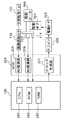
図2は、図1に示す画像形成部の各部と、中間転写ベルト101の駆動制御を行うベルト搬送制御部と、システムコントローラ120とを示すブロック図である。このベルト搬送制御部は、ASIC(Application Specified IC)204とドライバ205とを含む。
FIG. 2 is a block diagram illustrating each part of the image forming unit illustrated in FIG. 1, a belt conveyance control unit that performs drive control of the
システムコントローラ120には、CPU201、ROM202、およびRAM203が搭載されており、CPU201は、ROM202に格納されたプログラムに従い画像形成処理を実行する。RAM203は、CPU201のワーキングエリアを提供する。
The
ASIC204は、画像読取センサ116から送られたアナログ信号をAD変換するためのAD変換器205と、エンコーダ113から送られたアナログ信号をAD変換するためのAD変換器206と有し、AD変換されたデジタルデータは、システムコントローラ120に送信される。なお、駆動ローラホームポジションセンサ114からの出力信号はシステムコントローラ120に直接送信される。また、図示を省略したがベルトホームポジションセンサ115からの中間転写ベルト101の所定周回位置を示す信号もシステムコントローラ120に直接送信される。
The
ASIC204はまた、駆動モータ102(本実施の形態ではステッピングモータで構成される)を駆動するためのクロック生成器211を有し、このクロック生成器211は、CPU201からの指令により所定の駆動周波数をもつクロック信号を生成してドライバ205に供給する。これを受けたドライバ205は、所定の駆動周波数をもつ駆動クロックを生成して駆動モータ102(ステッピングモータ)に出力して駆動モータ102を駆動する。
The
つぎに、システムコントローラ120で行われる駆動モータ102の回転速度制御について説明する。
Next, the rotational speed control of the
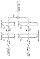
図3は、システムコントローラ120で生成され、RAM203に格納される各種データテーブルの相互関係を示す図であり、図4は、システムコントローラ120で行われる駆動モータ102に対する回転速度制御の処理手順を示すフローチャートである。以下、図3を参照しながら、図4に示すフローチャートに沿って説明する。
FIG. 3 is a diagram showing the interrelationship of various data tables generated by the
まず、駆動モータ102を、予め設定された所定の駆動周波数Vtをもつ駆動クロックにより駆動する(S1)。このとき、CPU201は、ASIC204から送信される、エンコーダ113の検出した駆動ローラ104の回転角速度を表すデジタル信号と、駆動ローラホームポジションセンサ114から送られた駆動ローラ104の回転基準位置(ホームポジション)の検知信号とに基づいて、該駆動ローラ104の回転角速度信号に対して随時低域通過型デジタルフィルタ処理を施して、駆動ギア103の偏心成分を抽出し、この偏心成分の駆動ローラ104の1周分をデータテーブル401として生成し、RAM203内に格納する(S2)。データテーブル401における駆動ギア103の偏心成分データの格納数は、駆動ローラ104の1回転中におけるエンコーダ113によるサンプリング数(マーク検出数)と等しい。なお、データテーブル401内に格納された駆動ギア103の偏心成分データによる正弦波プロファイルは、駆動ローラ104の1周分の速度ムラを模式的に示すことになる。
First, the
CPU201は、データテーブル401に格納された速度ムラプロファイルを基に、駆動ギア103の偏心成分を補正するための、駆動ローラ104の1周分の補正プロファイルを生成し、駆動テーブル402としてRAM203内に格納する(S3)。そして、駆動テーブル402と、エンコーダ113の検出した駆動ローラ104の回転角速度信号とに基づいて、駆動モータ102を補正駆動する(S4)。
The
この補正状態において、エンコーダ113の検出した駆動ローラ104の回転角速度が予め設定された所定範囲内に収まっているか否かを判断し(S5)、所定範囲内に収まっていればステップS6へ進み、所定範囲外であるならば、ステップS1に戻って、再度補正プロファイルを取得し直す。
In this correction state, it is determined whether or not the rotational angular velocity of the driving
ステップS6では、駆動ローラ104の回転角速度が安定していると判断し、中間転写ベルト101上に所定パターンを形成する。すなわち、該所定パターンは、感光ドラム105上に形成された所定形状のトナー像を中間転写ベルト101に転写することにより形成される。
In step S 6, it is determined that the rotational angular velocity of the driving
図5(A)は、中間転写ベルト101上に形成される所定パターンを示し、図5(B)は、該所定パターンを画像読取センサ116が検出したときの検出信号を示す図である。
FIG. 5A shows a predetermined pattern formed on the
所定パターンは、図5(A)に示すように、中間転写ベルト101上に距離Lで等間隔に形成される(N〜N+3)。これらの複数の所定パターンが形成された中間転写ベルト101が矢印Aの方向に移動したとき、中間転写ベルト101に対向して配置された画像読取センサ116がこれらの複数の所定パターンの検出を行い、図5(B)に示すような検出信号を画像読取センサ116が出力する。
As shown in FIG. 5A, the predetermined pattern is formed on the
ここで、中間転写ベルト101の移動速度をVt、画像読取センサ116からの各検出信号の出力タイミングの時間間隔をT0とすると、移動速度Vtが一定であれば、下記式(4)が成り立つ。
Here, if the moving speed of the
L/Vt=T0 ・・・(4)
一方、中間転写ベルト101の移動速度Vtが変動している場合は、上記式(4)は下記式(5)のようになる。
L / Vt = T0 (4)
On the other hand, when the moving speed Vt of the
L/(T0±ΔT)=Vt±ΔV ・・・(5)
ここで、ΔTは、移動速度Vtの変動に伴う時間間隔T0の変動分、ΔVは、移動速度Vtの変動分である。
L / (T0 ± ΔT) = Vt ± ΔV (5)
Here, ΔT is a variation in the time interval T0 accompanying a variation in the moving speed Vt, and ΔV is a variation in the moving speed Vt.
画像読取センサ116の各出力タイミングの時間間隔(T0±ΔT)は、ASIC204に内蔵されるタイマのカウント値として取得される。そしてCPU201が、取得された複数の時間間隔(T0±ΔT)に対して随時低域通過型デジタルフィルタ処理を施して、中間転写ベルト101の厚みムラ成分を抽出し、この厚みムラ成分の駆動ローラ104の1周分をデータテーブル403として生成し、RAM203内に格納する(S7)。データテーブル403における中間転写ベルト101の厚みムラ成分データの格納数は、画像読取センサ116で検出された所定パターンの数と等しい。なお、データテーブル403内に格納された中間転写ベルト101の厚みムラ成分データによる正弦波プロファイルは、中間転写ベルト101の1周分の速度ムラを模式的に示すことになる。
The time interval (T0 ± ΔT) of each output timing of the
そしてCPU201は、該プロファイルに基づいて、厚みムラを補正する補正係数プロファイル404を生成する(S8)。そして、ベルトホームポジションセンサ115によって中間転写ベルト101の所定周回位置(ホームポジション)が検出されたとき、乗算器405が、駆動テーブル402より算出されたモータ駆動周波数に対して、補正係数プロファイル404より読み出した厚みムラ補正係数を乗算して、補正後のモータ駆動周波数を算出し、フィードバック制御部(図7を参照して後述)に送出する(S9)。
Then, the
また中間転写ベルト101の移動速度の検出手法は、上記実施の形態に限定されるものではなく、上述した手法以外にも例えば、予め中間転写ベルト101の厚みムラを計測器等により測定しておき、その測定値に基づきプロファイルを算出する手法や、中間転写ベルト101上に形成する所定パターンをトナー像ではなく、ベルト自体に予めマーキングしておき、該マークを検出する手法であってもよい。
Further, the method for detecting the moving speed of the
次に、画像形成動作中のフィードバック補正について説明する。 Next, feedback correction during the image forming operation will be described.
図6は、画像形成動作中に外乱ショックがあった場合に中間転写ベルト101に発生する移動速度変動およびその補正について示す図である。
FIG. 6 is a diagram showing movement speed fluctuations generated in the
図6において縦軸は中間転写ベルト(ITB)101の移動速度を、横軸は時間を示す。本来、中間転写ベルト101の移動速度は一定であるが、外乱ショックがあった場合、中間転写ベルト101に瞬間的な移動速度変動P1が発生する。この移動速度変動P1によって、図6に示す斜線部の面積に相当する量(累積値、積分値)の画像位置ずれΔSが発生してしまう。この画像位置ずれΔSは、次に中間転写ベルト101の所定周回位置(ホームポジション)が検出されるまで解消されない。そこで、そのショック収束直後に、移動速度変動P1で発生する斜線部の面積に相当する面積をもつ速度補正P2を逆速度方向に加えるようにする。これによって、外乱ショックに起因する中間転写ベルト101の移動速度変動に伴う画像位置ずれをなくすことができる。
In FIG. 6, the vertical axis represents the moving speed of the intermediate transfer belt (ITB) 101, and the horizontal axis represents time. Originally, the movement speed of the
図7は、フィードバック制御部の構成を示すブロック図である。このフィードバック制御部は、システムコントローラ120によって実現される機能をブロック化して示すものである。
FIG. 7 is a block diagram illustrating a configuration of the feedback control unit. This feedback control unit shows the functions realized by the
図7において501はバッファ部であり、図3の乗算器405から順次出力される目標値(補正後のモータ駆動周波数に対応するデータ)を一時格納する。このバッファ部501は、後述するフィルタ部507から比較部504に入力される信号とのタイミングを合わせるために機能するものである。502は演算部であり、バッファ部501から読み出された目標値を、駆動モータ102(ステッピングモータ)へ供給するパルスの駆動周波数に対応するデジタルデータとなるPPSデータへ変換する。506は、エンコーダ113から送られた駆動ローラ104の回転角速データを格納する格納部であり、507は、格納部506から読み出された回転角速データに対してフィルタ処理を施すフィルタ部である。504は、フィルタ部507の出力とバッファ部501の出力とを比較する比較部であり、505は係数算出部である、係数算出部505は、比較部504の比較結果に応じて、演算部502からの出力データを増減させるための係数を出力する。503は合成演算部であり、演算部502からの出力データに、係数算出部505からの係数を乗算し、ASIC204に出力する。
In FIG. 7,
図8は、フィードバック制御部の動作手順を示すフローチャートである。 FIG. 8 is a flowchart showing an operation procedure of the feedback control unit.
まず、画像形成動作中のエンコーダ113の出力値を格納部506に一時的に格納する(S51)。このエンコーダ113の出力値を格納部506から読み出し、フィルタ部507でノイズ除去を行い、比較部504へ入力する。それと同時に、バッファ部501から目標値を読み出して比較部504に入力する。
First, the output value of the
比較部504ではその両者を比較し、動作中のエンコーダ113の出力値が、目標値を中心とする所定の許容範囲内にあるか否かを判断する(S52)。また、エンコーダ113の出力値が目標値よりも大きいか、または小さいかを判断する。エンコーダ113の出力値が所定の許容範囲外にあれば、外乱ショックが発生したと判断して、ステップS53へ進んで、この外乱ショックが継続しているか否かを判別し、継続していればステップS51へ戻り、終了していればステップS54へ進む。ステップS54では、外乱ショックが発生したとことを表すフラグを立てる。
The
ステップS52で、エンコーダ113の出力値が所定の許容範囲内にあると判断されれば、ステップS55へ進んで、外乱ショックが発生したとことを表すフラグが立っているか否かを判別し、該フラグが立っていればステップS56へ進み、まだ立っていなければステップS51へ戻る。
If it is determined in step S52 that the output value of the
ステップS56では、外乱ショックに伴う速度変動を補正すべき期間(PPSデータ変更区間)を算出する。そしてステップS57で、該補正が開始されてその補正期間が経過済みであるか否かを判別する。補正期間が経過済みであればステップS51へ戻り、補正期間が未だ残っていればステップS58へ進む。 In step S56, a period (PPS data change section) in which the speed fluctuation accompanying the disturbance shock is to be corrected is calculated. In step S57, it is determined whether or not the correction has been started and the correction period has elapsed. If the correction period has elapsed, the process returns to step S51, and if the correction period still remains, the process proceeds to step S58.
ステップS58では、外乱ショックに伴う速度変動の補正を行う。すなわち、係数算出部505が、画像形成時のエンコーダ出力値が目標値よりも大きいときには低い周波数のPPSデータとなるような係数を、逆に、画像形成時のエンコーダ出力値が目標値よりも小さいときには高い周波数のPPSデータとなるような係数を出力する。合成演算部503は、こうした係数を、演算部502からのPPSデータに乗算し、ASIC204に出力する。
In step S58, the speed fluctuation associated with the disturbance shock is corrected. That is, the
以上述べたような回転速度補正制御を、画像形成動作中において常に継続することにより、紙媒体に形成された画像において濃度ムラ及び色ずれを低減し、高画質化を図ることができる。 By continuously continuing the rotational speed correction control as described above during the image forming operation, it is possible to reduce density unevenness and color misregistration in an image formed on a paper medium and improve image quality.
〔他の実施の形態〕
なお、上記の実施の形態では、外乱ショックが収まってから補正制御を実施するようにしているが、これに代わって、外乱ショックが始まった瞬間から補正制御を実施するようにしてもよい。
[Other Embodiments]
In the above-described embodiment, the correction control is performed after the disturbance shock is settled. Alternatively, the correction control may be performed from the moment when the disturbance shock starts.
また、本発明の目的は、前述した実施の形態の機能を実現するソフトウェアのプログラムコードを記録した記憶媒体を、システムまたは装置に供給し、そのシステムまたは装置のコンピュータ(またはCPU、MPU等)が記憶媒体に格納されたプログラムコードを読み出して実行することによっても達成される。 Another object of the present invention is to supply a storage medium storing software program codes for realizing the functions of the above-described embodiments to a system or apparatus, and a computer (or CPU, MPU, etc.) of the system or apparatus. It is also achieved by reading and executing the program code stored in the storage medium.
この場合、記憶媒体から読み出されたプログラムコード自体が本発明の新規な機能を実現することになり、そのプログラムコードを記憶した記憶媒体およびプログラムは本発明を構成することになる。 In this case, the program code itself read from the storage medium realizes the novel function of the present invention, and the storage medium and program storing the program code constitute the present invention.
また、プログラムコードを供給するための記憶媒体としては、例えば、フレキシブルディスク、ハードディスク、光ディスク、光磁気ディスク、CD−ROM、CD−R、CD−RW、DVD−ROM、DVD−RAM、DVD−RW、DVD+RW、磁気テープ、不揮発性のメモリカード、ROM等を用いることができる。或いは、上記プログラムは、インターネット、商用ネットワーク、若しくはローカルエリアネットワーク等に接続される他のコンピュータやデータベース等からダウンロードすることにより供給される。 The storage medium for supplying the program code is, for example, a flexible disk, hard disk, optical disk, magneto-optical disk, CD-ROM, CD-R, CD-RW, DVD-ROM, DVD-RAM, DVD-RW. DVD + RW, magnetic tape, nonvolatile memory card, ROM, etc. can be used. Alternatively, the program is supplied by downloading from another computer or database connected to the Internet, a commercial network, a local area network, or the like.
また、コンピュータが読み出したプログラムコードを実行することにより、前述した実施の形態の機能が実現されるだけでなく、そのプログラムコードの指示に基づき、コンピュータ上で稼動しているOS(オペレーティングシステム)等が実際の処理の一部または全部を行い、その処理によって前述した実施の形態の機能が実現される場合も含まれる。 Further, by executing the program code read by the computer, not only the functions of the above-described embodiments are realized, but also an OS (operating system) or the like running on the computer based on the instruction of the program code. Includes a case where part or all of the actual processing is performed and the functions of the above-described embodiments are realized by the processing.
更に、記憶媒体から読み出されたプログラムコードが、コンピュータに挿入された機能拡張ボードやコンピュータに接続された機能拡張ユニットに備わるメモリに書き込まれた後、そのプログラムコードの指示に基づき、その機能拡張ボードや機能拡張ユニットに備わるCPU等が実際の処理の一部または全部を行い、その処理によって前述した実施の形態の機能が実現される場合も含まれる。 Further, after the program code read from the storage medium is written in a memory provided in a function expansion board inserted into the computer or a function expansion unit connected to the computer, the function expansion is performed based on the instruction of the program code. This includes the case where the CPU or the like provided in the board or the function expansion unit performs part or all of the actual processing and the functions of the above-described embodiments are realized by the processing.
101 中間転写ベルト(ベルト)
102 駆動モータ
103 駆動ギア
104 駆動ローラ
105 感光ドラム
113 エンコーダ(回転速度検出手段)
114 駆動ローラホームポジションセンサ
115 ベルトホームポジションセンサ
116 画像読取センサ
120 システムコントローラ(累積値検出手段,補正手段)
201 CPU
202 ROM
203 RAM
204 ASIC(Application Specified IC)
205 ドライバ
501 バッファ部
502 演算部
503 合成演算部
504 比較部
505 係数算出部
506 格納部
507 フィルタ部
101 Intermediate transfer belt (belt)
102
114 Drive roller
201 CPU
202 ROM
203 RAM
204 ASIC (Application Specified IC)
205
Claims (8)
前記駆動ローラの回転速度を検出する回転速度検出手段と、
前記回転速度検出手段の出力値が予め設定された許容範囲から外れたことに応じて、外乱による前記回転速度の一時的変動の発生を検出する外乱検出手段と、
前記外乱検出手段により前記外乱による前記回転速度の一時的変動の発生が検出されたことに応じて、前記回転速度検出手段によって検出された回転速度に含まれる該回転速度の一時的変動量の累積値を検出する累積値検出手段と、
前記回転速度検出手段の出力値が前記許容範囲から外れた後、前記出力値が前記許容範囲内に収束したことに応じて、前記駆動ローラの回転速度を補正する補正期間を算出し、算出した前記補正期間が経過するまで前記累積値検出手段によって検出された累積値を打ち消すように前記駆動ローラの回転速度を補正する補正手段と
を有することを特徴とする画像形成装置。 In an image forming apparatus comprising a belt, a driving roller for rotating the belt, and a belt conveying device including at least a driving motor for rotationally driving the driving roller.
Rotation speed detection means for detecting the rotation speed of the drive roller;
Disturbance detecting means for detecting occurrence of a temporary fluctuation of the rotation speed due to a disturbance in response to an output value of the rotation speed detecting means being out of a preset allowable range;
Accumulation of the temporary fluctuation amount of the rotation speed included in the rotation speed detected by the rotation speed detection means in response to the occurrence of the temporary fluctuation of the rotation speed due to the disturbance detected by the disturbance detection means. A cumulative value detecting means for detecting a value;
After the output value of the rotational speed detecting means deviates from the allowable range, a correction period for correcting the rotational speed of the drive roller is calculated in accordance with the fact that the output value has converged within the allowable range. An image forming apparatus comprising: a correcting unit that corrects the rotational speed of the driving roller so as to cancel the accumulated value detected by the accumulated value detecting unit until the correction period elapses .
前記ベルト速度検出手段によって検出された前記ベルトの周回速度に含まれる速度ムラを算出する速度ムラ算出手段と、
前記速度ムラ算出手段によって算出された速度ムラに基づき、前記駆動モータの目標回転速度を決定する決定手段と
を更に有することを特徴とする請求項1記載の画像形成装置。 Belt speed detecting means for detecting a plurality of predetermined images formed on the belt at predetermined intervals and detecting a circumferential speed of the belt based on a difference in timing at which each predetermined image is detected;
Speed unevenness calculating means for calculating speed unevenness included in the belt rotation speed detected by the belt speed detecting means;
The image forming apparatus according to claim 1, further comprising: a determining unit that determines a target rotational speed of the drive motor based on the speed unevenness calculated by the speed unevenness calculating unit.
それぞれ協働して回転することでカラー画像を形成する複数の回転体と、
前記形成されるカラー画像の画質劣化の原因となる前記回転体の回転速度の変動量を検出する検出ユニットと、
前記検出ユニットの出力値が予め設定された許容範囲から外れたことに応じて、外乱による前記回転速度の一時的変動の発生を検出する外乱検出ユニットと、
前記外乱検出ユニットにより前記外乱による前記回転速度の一時的変動の発生が検出されたことに応じて、前記検出ユニットで検出された変動量の累積値を検出し、前記検出ユニットの出力値が前記許容範囲から外れた後、前記出力値が前記許容範囲内に収束したことに応じて、前記回転体の回転速度を補正する補正期間を算出し、算出した前記補正期間が経過するまで前記累積値を打ち消すように前記回転体の回転速度を補正する回転速度補正ユニットと
を有することを特徴とする画像形成装置。 An image forming apparatus for forming a color image,
A plurality of rotating bodies that form a color image by rotating in cooperation with each other;
A detection unit that detects a fluctuation amount of a rotational speed of the rotating body that causes image quality degradation of the formed color image;
A disturbance detection unit that detects the occurrence of a temporary fluctuation in the rotational speed due to a disturbance in response to the output value of the detection unit being out of a preset allowable range;
In response to the occurrence of the temporary fluctuation of the rotational speed due to the disturbance detected by the disturbance detection unit, the accumulated value of the fluctuation amount detected by the detection unit is detected, and the output value of the detection unit is the After deviating from the allowable range, a correction period for correcting the rotation speed of the rotating body is calculated in response to the output value having converged within the allowable range, and the accumulated value is calculated until the calculated correction period elapses. An image forming apparatus comprising: a rotation speed correction unit that corrects the rotation speed of the rotating body so as to cancel out the image.
それぞれ色の異なる複数の現像材によって形成された現像材の像を記録材に転写するための転写ベルトと、
前記転写ベルトを駆動するための駆動ローラと、
前記駆動ローラを駆動するための駆動ギアと、
前記駆動ギアを駆動するための駆動モータと
が含まれることを特徴とする請求項7に記載の画像形成装置。 In the plurality of rotating bodies,
A transfer belt for transferring an image of a developer formed by a plurality of developers of different colors to a recording material;
A driving roller for driving the transfer belt;
A drive gear for driving the drive roller;
The image forming apparatus according to claim 7, further comprising: a drive motor for driving the drive gear.
Priority Applications (2)
| Application Number | Priority Date | Filing Date | Title |
|---|---|---|---|
| JP2004317029A JP4630631B2 (en) | 2004-10-29 | 2004-10-29 | Image forming apparatus |
| US11/258,299 US20060093410A1 (en) | 2004-10-29 | 2005-10-25 | Image forming apparatus and method for controlling the same |
Applications Claiming Priority (1)
| Application Number | Priority Date | Filing Date | Title |
|---|---|---|---|
| JP2004317029A JP4630631B2 (en) | 2004-10-29 | 2004-10-29 | Image forming apparatus |
Publications (3)
| Publication Number | Publication Date |
|---|---|
| JP2006126654A JP2006126654A (en) | 2006-05-18 |
| JP2006126654A5 JP2006126654A5 (en) | 2007-02-08 |
| JP4630631B2 true JP4630631B2 (en) | 2011-02-09 |
Family
ID=36262087
Family Applications (1)
| Application Number | Title | Priority Date | Filing Date |
|---|---|---|---|
| JP2004317029A Expired - Fee Related JP4630631B2 (en) | 2004-10-29 | 2004-10-29 | Image forming apparatus |
Country Status (2)
| Country | Link |
|---|---|
| US (1) | US20060093410A1 (en) |
| JP (1) | JP4630631B2 (en) |
Families Citing this family (8)
| Publication number | Priority date | Publication date | Assignee | Title |
|---|---|---|---|---|
| DE102006032703A1 (en) * | 2006-07-14 | 2008-01-24 | OCé PRINTING SYSTEMS GMBH | Method and arrangement for generating a predetermined rotational speed of an endless belt-shaped image carrier |
| JP4591494B2 (en) * | 2007-09-25 | 2010-12-01 | ブラザー工業株式会社 | Image forming apparatus |
| JP5203823B2 (en) * | 2008-07-08 | 2013-06-05 | キヤノン株式会社 | Image forming apparatus, method for controlling image forming apparatus, program, and storage medium |
| JP5586919B2 (en) * | 2009-10-30 | 2014-09-10 | キヤノン株式会社 | Movement detection apparatus and recording apparatus |
| JP5488450B2 (en) * | 2010-12-24 | 2014-05-14 | ブラザー工業株式会社 | Image forming apparatus |
| KR20130007886A (en) * | 2011-07-11 | 2013-01-21 | 삼성전자주식회사 | Image forming apparatus, motor controlling apparatus and method for controlling of motor |
| JP5696714B2 (en) * | 2012-11-07 | 2015-04-08 | コニカミノルタ株式会社 | Paper conveying apparatus, image forming apparatus, and push-in amount adjusting method |
| EP3152142B1 (en) | 2014-06-05 | 2020-04-22 | Hewlett-Packard Development Company, L.P. | Printing device, corresponding printing system, and method of operating a printing device |
Citations (7)
| Publication number | Priority date | Publication date | Assignee | Title |
|---|---|---|---|---|
| JPH0243574A (en) * | 1988-08-03 | 1990-02-14 | Fuji Xerox Co Ltd | Method and device for controlling rotation in multiplex transfer device |
| JPH052310A (en) * | 1991-06-26 | 1993-01-08 | Toshiba Corp | Image forming device |
| JPH0863000A (en) * | 1994-08-26 | 1996-03-08 | Fuji Xerox Co Ltd | Image forming device |
| JPH11184185A (en) * | 1997-12-19 | 1999-07-09 | Ricoh Co Ltd | Image forming device |
| JP2000098806A (en) * | 1998-09-28 | 2000-04-07 | Minolta Co Ltd | Image forming device |
| JP2000298407A (en) * | 1999-02-12 | 2000-10-24 | Ricoh Co Ltd | Image forming device |
| JP2002072816A (en) * | 2000-09-01 | 2002-03-12 | Matsushita Electric Ind Co Ltd | Image forming device |
Family Cites Families (5)
| Publication number | Priority date | Publication date | Assignee | Title |
|---|---|---|---|---|
| JPH07281491A (en) * | 1994-04-05 | 1995-10-27 | Konica Corp | Color image forming device |
| JP3564953B2 (en) * | 1996-10-28 | 2004-09-15 | 富士ゼロックス株式会社 | Image forming apparatus and control method thereof |
| US6771919B2 (en) * | 2001-07-18 | 2004-08-03 | Ricoh Company, Ltd. | Image forming apparatus with reduced variation of rotation speed of image carrier |
| JP2004220007A (en) * | 2002-12-27 | 2004-08-05 | Ricoh Co Ltd | Transfer device, image forming device, and belt moving speed correcting method |
| JP2006119541A (en) * | 2004-10-25 | 2006-05-11 | Canon Inc | Color image forming apparatus and its control method |
-
2004
- 2004-10-29 JP JP2004317029A patent/JP4630631B2/en not_active Expired - Fee Related
-
2005
- 2005-10-25 US US11/258,299 patent/US20060093410A1/en not_active Abandoned
Patent Citations (7)
| Publication number | Priority date | Publication date | Assignee | Title |
|---|---|---|---|---|
| JPH0243574A (en) * | 1988-08-03 | 1990-02-14 | Fuji Xerox Co Ltd | Method and device for controlling rotation in multiplex transfer device |
| JPH052310A (en) * | 1991-06-26 | 1993-01-08 | Toshiba Corp | Image forming device |
| JPH0863000A (en) * | 1994-08-26 | 1996-03-08 | Fuji Xerox Co Ltd | Image forming device |
| JPH11184185A (en) * | 1997-12-19 | 1999-07-09 | Ricoh Co Ltd | Image forming device |
| JP2000098806A (en) * | 1998-09-28 | 2000-04-07 | Minolta Co Ltd | Image forming device |
| JP2000298407A (en) * | 1999-02-12 | 2000-10-24 | Ricoh Co Ltd | Image forming device |
| JP2002072816A (en) * | 2000-09-01 | 2002-03-12 | Matsushita Electric Ind Co Ltd | Image forming device |
Also Published As
| Publication number | Publication date |
|---|---|
| US20060093410A1 (en) | 2006-05-04 |
| JP2006126654A (en) | 2006-05-18 |
Similar Documents
| Publication | Publication Date | Title |
|---|---|---|
| US7099614B2 (en) | Color image forming apparatus and method of controlling same | |
| US6941096B2 (en) | Belt drive control device and image forming apparatus including the same | |
| JP5013858B2 (en) | Image forming apparatus | |
| JP4865283B2 (en) | Image forming apparatus and phase alignment method for a plurality of image carriers | |
| JP2006047990A (en) | Image forming apparatus, and image transferring method | |
| US20060093410A1 (en) | Image forming apparatus and method for controlling the same | |
| JP5196759B2 (en) | Image forming apparatus | |
| JP4641401B2 (en) | Image carrier speed variation phase difference detection method and image forming apparatus using the method | |
| JP4091899B2 (en) | Belt drive | |
| JP2007052111A (en) | Image forming apparatus | |
| JP4533198B2 (en) | Drive control device and image forming apparatus | |
| US6725005B2 (en) | Drive control method of photoreceptor drum and image forming apparatus | |
| JP4263583B2 (en) | Image forming apparatus | |
| US7079797B2 (en) | Offset preventing color image forming apparatus | |
| JP5556092B2 (en) | Belt drive control device, belt drive control method, and image forming apparatus | |
| JP2005115398A (en) | Belt drive control method, its device, belt device, image forming device, process cartridge, program and recording medium | |
| JP2001083762A (en) | Multicolor image forming device | |
| JP6335435B2 (en) | Image forming apparatus | |
| JP4503417B2 (en) | Image forming apparatus | |
| JP2001066909A (en) | Moving speed controller | |
| JP5041396B2 (en) | Rotating body driving device and image forming apparatus having the same | |
| JP2001147573A (en) | Device and method for forming image | |
| JP4667033B2 (en) | Conveyance control method and image forming apparatus | |
| JP2000194176A (en) | Image forming device and controlling method thereof | |
| JP3225686B2 (en) | Color image forming equipment |
Legal Events
| Date | Code | Title | Description |
|---|---|---|---|
| RD03 | Notification of appointment of power of attorney |
Free format text: JAPANESE INTERMEDIATE CODE: A7423 Effective date: 20060419 |
|
| A521 | Request for written amendment filed |
Free format text: JAPANESE INTERMEDIATE CODE: A523 Effective date: 20061215 |
|
| A621 | Written request for application examination |
Free format text: JAPANESE INTERMEDIATE CODE: A621 Effective date: 20061215 |
|
| RD05 | Notification of revocation of power of attorney |
Free format text: JAPANESE INTERMEDIATE CODE: A7425 Effective date: 20070626 |
|
| A977 | Report on retrieval |
Free format text: JAPANESE INTERMEDIATE CODE: A971007 Effective date: 20090501 |
|
| A131 | Notification of reasons for refusal |
Free format text: JAPANESE INTERMEDIATE CODE: A131 Effective date: 20090630 |
|
| A521 | Request for written amendment filed |
Free format text: JAPANESE INTERMEDIATE CODE: A523 Effective date: 20090831 |
|
| A131 | Notification of reasons for refusal |
Free format text: JAPANESE INTERMEDIATE CODE: A131 Effective date: 20100223 |
|
| A521 | Request for written amendment filed |
Free format text: JAPANESE INTERMEDIATE CODE: A523 Effective date: 20100420 |
|
| TRDD | Decision of grant or rejection written | ||
| A01 | Written decision to grant a patent or to grant a registration (utility model) |
Free format text: JAPANESE INTERMEDIATE CODE: A01 Effective date: 20101108 |
|
| A01 | Written decision to grant a patent or to grant a registration (utility model) |
Free format text: JAPANESE INTERMEDIATE CODE: A01 |
|
| A61 | First payment of annual fees (during grant procedure) |
Free format text: JAPANESE INTERMEDIATE CODE: A61 Effective date: 20101115 |
|
| FPAY | Renewal fee payment (event date is renewal date of database) |
Free format text: PAYMENT UNTIL: 20131119 Year of fee payment: 3 |
|
| R150 | Certificate of patent or registration of utility model |
Free format text: JAPANESE INTERMEDIATE CODE: R150 |
|
| LAPS | Cancellation because of no payment of annual fees |