JP2005292612A - Position adjusting method and device for fixing device - Google Patents
Position adjusting method and device for fixing device Download PDFInfo
- Publication number
- JP2005292612A JP2005292612A JP2004109595A JP2004109595A JP2005292612A JP 2005292612 A JP2005292612 A JP 2005292612A JP 2004109595 A JP2004109595 A JP 2004109595A JP 2004109595 A JP2004109595 A JP 2004109595A JP 2005292612 A JP2005292612 A JP 2005292612A
- Authority
- JP
- Japan
- Prior art keywords
- frame
- fixing device
- position adjusting
- hole
- transfer belt
- Prior art date
- Legal status (The legal status is an assumption and is not a legal conclusion. Google has not performed a legal analysis and makes no representation as to the accuracy of the status listed.)
- Granted
Links
- 238000000034 method Methods 0.000 title claims description 12
- 230000032258 transport Effects 0.000 description 19
- 239000000758 substrate Substances 0.000 description 6
- 238000004140 cleaning Methods 0.000 description 3
- 229910000831 Steel Inorganic materials 0.000 description 2
- 238000004519 manufacturing process Methods 0.000 description 2
- 239000000463 material Substances 0.000 description 2
- 230000000149 penetrating effect Effects 0.000 description 2
- 238000003825 pressing Methods 0.000 description 2
- 239000010959 steel Substances 0.000 description 2
- 230000037303 wrinkles Effects 0.000 description 2
- 238000004049 embossing Methods 0.000 description 1
- 238000012423 maintenance Methods 0.000 description 1
- 239000002184 metal Substances 0.000 description 1
- 230000000007 visual effect Effects 0.000 description 1
Images
Landscapes
- Electrophotography Configuration And Component (AREA)
Abstract
Description
本発明は、複写機等の画像形成装置に関するものである。 The present invention relates to an image forming apparatus such as a copying machine.
以下、画像形成装置として複写機を例として説明する。転写ベルトを備えた複写機においては、用紙を搬送する転写ベルトと、用紙搬送方向に対して転写ベルトの下流に配置される定着装置との平行度(装着状態)によって用紙の搬送状態が大きく変化するため、その平行度を正確に合わせておかないとシワが発生しやすくなったりする。すなわち、転写ベルト上では用紙の搬送は転写ベルトに依存するが、定着装置内では定着ローラ対の回転に用紙が従動するため、両者の平行度が悪いと用紙を引っ張る側と用紙を押す側とで用紙の進行方向が一致せず、シワとなってしまうのである。 Hereinafter, a copying machine will be described as an example of the image forming apparatus. In a copying machine equipped with a transfer belt, the paper transport state varies greatly depending on the parallelism (attached state) between the transfer belt that transports the paper and the fixing device disposed downstream of the transfer belt in the paper transport direction. Therefore, wrinkles are likely to occur unless the parallelism is accurately adjusted. In other words, the conveyance of the paper on the transfer belt depends on the transfer belt, but the paper is driven by the rotation of the fixing roller pair in the fixing device, so that if the parallelism between the two is poor, the paper is pulled and the paper is pushed. As a result, the paper traveling directions do not match, and wrinkles occur.
そこで従来は、複写機の生産ラインにおいて、定着装置の位置を転写ベルトの位置に対して合わし込む方法がとられていた。例えば、フレーム内の所定位置に搬送装置を固定し、フレーム底板から突出するピンに対して定着装置の底板に設けた位置決めの丸穴を差し込み、定着装置をそのピンを中心にして回転して位置を振ることで平行にし、最終的に定着装置の底板を前後の複数箇所でビス止めしてフレーム底板に取付けていた。 Therefore, conventionally, a method of aligning the position of the fixing device with the position of the transfer belt in the production line of the copying machine has been used. For example, the transport device is fixed at a predetermined position in the frame, a positioning round hole provided in the bottom plate of the fixing device is inserted into a pin protruding from the frame bottom plate, and the fixing device is rotated around the pin to be positioned. The bottom plate of the fixing device was finally screwed at a plurality of positions on the front and rear sides and attached to the frame bottom plate.
しかし、このような方法では、例えば、市場等でメンテナンス時にサービスマンが定着装置を取り外し、再度取付ける際に、生産ラインで一端調整した定着装置の位置を目視のみで再現することはほとんど不可能であり、元の位置に定着装置をセットし直す調整作業に時間が掛かってしまうという問題があった。 However, with such a method, for example, when a serviceman removes and re-installs the fixing device during maintenance in the market or the like, it is almost impossible to reproduce the position of the fixing device adjusted once on the production line by visual observation. There is a problem that it takes time to perform the adjustment work for resetting the fixing device to the original position.
このような問題に対し、例えば特許文献1には、像担持体(感光ドラム)の回転中心軸を支持してその位置を調整するための部材であって、一定量αだけ水平方向にオフセットした位置にボスを設けて成る位置調整部材と、前記位置調整部材が装着される本体側(シャーシ)に形成された略水平方向に長い長孔であって、位置調整部材の前記ボスが嵌合して該位置調整部材の水平方向への移動を許容する嵌合孔とにより、各像担持体がそれぞれに対応したスキャナユニットに対して平行となるよう調整するものが記載されている。 To deal with such a problem, for example, Patent Document 1 describes a member for supporting the rotation center axis of an image carrier (photosensitive drum) and adjusting its position, and is offset in the horizontal direction by a fixed amount α. A position adjustment member provided with a boss at a position, and a long hole formed in a substantially horizontal direction formed on a main body side (chassis) to which the position adjustment member is mounted, and the boss of the position adjustment member is fitted to the position adjustment member. Thus, it is described that each image carrier is adjusted to be parallel to the corresponding scanner unit by a fitting hole that allows the position adjusting member to move in the horizontal direction.
また、特許文献2には、複写機の下部フレームに対して上部フレームを開閉可能に設けた装置において、上部フレームに設けた画像形成ユニットのフレームに押圧部を配置し、上部フレームを閉じた際に、下部フレームに設けた搬送ユニットの位置を制御できるようにしたものが記載されている。すなわち、前記搬送ユニットは、取り付け位置を調整可能な突き当てガイドを設けており、前記突き当てガイドの突き当て面が押圧部に押圧されて移動し、搬送ユニットに設けたローラ部材の位置決めを行い、用紙の搬送状態を調整することができる。
上記特許文献1の方法は、ボスを設けた位置調整部材一つで感光ドラムをシャーシの側壁に支持するものであり、感光ドラムのように軽い部材の場合はよいが、定着装置のように重いものになると、シャーシの強度的に不安がある。また、定着装置の場合は、転写ベルトに対する平行度、すなわち水平方向の位置調整が重要なのであって、上下方向の位置調整はシャーシの底壁に載置してしまえば、ほとんど問題とならないと考えられる。 The method of Patent Document 1 supports a photosensitive drum on a side wall of a chassis with a single position adjusting member provided with a boss. A light member such as a photosensitive drum may be used, but it is heavy as a fixing device. When it comes to things, there are concerns about the strength of the chassis. In the case of a fixing device, parallelism with respect to the transfer belt, that is, horizontal position adjustment is important, and if the vertical position adjustment is placed on the bottom wall of the chassis, there will be little problem. It is done.
また、上記特許文献2の方法は、転写ベルトと定着装置のように同一のフレームに設置されるもの同士の位置調整には利用できない。また、可動部が多いため故障が頻発する可能性も高いと考えられる。 Further, the method of Patent Document 2 cannot be used to adjust the positions of those installed on the same frame, such as a transfer belt and a fixing device. Moreover, since there are many movable parts, it is considered that the possibility of frequent failures is high.
上記課題を解決するために本発明の定着装置の位置調整方法は、用紙を搬送する転写ベルトが搭載されたフレームに前記転写ベルトの位置よりも用紙搬送方向の下流側の位置において定着装置を装着し、該定着装置の位置を調整する調整方法であって、用紙搬送方向に対して直交する方向の一端側で前記定着装置の前記フレームに対する位置決めをし、他端側で前記定着装置の前記転写ベルトに対する位置を調整することを特徴とする。 In order to solve the above problems, the fixing device position adjusting method according to the present invention is such that a fixing device is mounted on a frame on which a transfer belt for transporting paper is mounted at a position downstream of the transfer belt in the paper transport direction. An adjustment method for adjusting the position of the fixing device, wherein the fixing device is positioned with respect to the frame at one end side in a direction orthogonal to the sheet conveying direction, and the transfer of the fixing device is performed at the other end side. The position relative to the belt is adjusted.
また、本発明の位置調整装置は、用紙を搬送する転写ベルトが搭載されたフレームと、該フレームの用紙搬送方向に対して直交する方向で対面する側壁の一方に突設された突起棒と、前記定着装置の一端面に設けられ前記突起棒が嵌合される穴と、突起棒を有する位置調整部材と、前記フレームの用紙搬送方向に対して直交する方向で対面する側壁の他方に貫設され前記位置調整部材の突起棒が挿通される長穴と、前記フレームの外側に仮止めされ前記フレームの長穴に対応する位置に前記位置調整部材の突起棒が挿通される長穴を有する位置調整板と、前記定着装置の他端面に設けられ前記位置調整部材の突起棒が嵌合される穴とを備え、
用紙搬送方向に対して直交する方向の一端側で前記フレームの突起棒と前記定着装置の一端面の穴とを嵌合させて前記定着装置の前記フレームに対する位置決めをし、他端側で前記フレームの長穴と該フレームに仮止めされた前記位置調整板の長穴に前記位置調整部材の突起棒を挿通するとともに、該突起棒と前記定着装置の他端面の穴とを嵌合させて、前記位置調整部材を前記位置調整板上で用紙搬送方向に摺動させることにより、前記定着装置の前記転写ベルトに対する位置を調整することを特徴とする。
Further, the position adjusting device of the present invention includes a frame on which a transfer belt that conveys a sheet is mounted, a projecting bar that protrudes from one of the side walls facing the frame in a direction orthogonal to the sheet conveying direction, A hole provided in one end face of the fixing device, into which the protruding bar is fitted, a position adjusting member having the protruding bar, and the other side wall of the frame facing in a direction perpendicular to the sheet conveying direction. And a slot having a slot through which the projection bar of the position adjustment member is inserted, and a slot that is temporarily fixed to the outside of the frame and into which the projection bar of the position adjustment member is inserted. An adjustment plate, and a hole provided on the other end surface of the fixing device, into which the protrusion bar of the position adjustment member is fitted,
The projecting rod of the frame and a hole on one end surface of the fixing device are fitted on one end side in a direction orthogonal to the sheet conveying direction to position the fixing device with respect to the frame, and the frame on the other end side. And inserting the protrusion rod of the position adjustment member into the elongated hole of the position adjustment plate temporarily fixed to the frame, and fitting the protrusion rod and the hole on the other end surface of the fixing device, The position of the fixing device relative to the transfer belt is adjusted by sliding the position adjusting member on the position adjusting plate in the sheet conveying direction.
そして、定着装置の位置調整のために、前記位置調整板に用紙搬送方向に等間隔で配置される目盛りを設けたこと特徴とする。 In order to adjust the position of the fixing device, the position adjusting plate is provided with scales arranged at equal intervals in the paper transport direction.
本発明によると、定着装着のフレームに対する装着位置を適切な位置に容易に調整し、フレーム内で定着装置と転写ベルトとの平行度を保持することができる。また、一度このようにして定着装置の装着位置の調整をすれば、ネジを一本外すだけで、位置調整板と位置調整部材とを一体で取り外し、定着装置を取り外すことができるため、サービス時などに定着装置を元の位置に労せず装着することができる。 According to the present invention, it is possible to easily adjust the mounting position of the fixing mounting with respect to the frame to an appropriate position, and to maintain the parallelism between the fixing device and the transfer belt within the frame. In addition, once the fixing device mounting position is adjusted in this way, the fixing device can be removed by detaching the position adjusting plate and the position adjusting member by simply removing one screw. For example, the fixing device can be attached to the original position without any effort.
以下、本発明を実施するための最良の形態について図面を参照して説明する。但し、この実施の形態に記載されている構成部品の寸法、材質、形状、その相対配置などは特に特定的な記載がない限り、この発明の範囲をそれのみに限定する趣旨ではなく、単なる説明例に過ぎない。 The best mode for carrying out the present invention will be described below with reference to the drawings. However, the dimensions, materials, shapes, relative arrangements, and the like of the component parts described in this embodiment are not intended to limit the scope of the present invention only to the description unless otherwise specified. It is just an example.
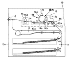
まず、図1を参照して、本発明による調整装置が用いられる画像形成装置について説明する。図示の画像形成装置10は、給紙装置11を備えており、この給紙装置11は画像形成装置筐体(以下単に筐体と呼ぶ)10aに装着されている。この給紙装置11からは、用紙搬送ローラ12a及びレジストローラ12bを備えた搬送ユニット12を介して画像形成部13に記録用紙が搬送される。
First, an image forming apparatus in which an adjusting device according to the present invention is used will be described with reference to FIG. The illustrated
画像形成部13には、例えば、感光体ドラム13aが備えられ、感光体ドラム13aの周囲には、帯電体13b、現像器13c、及びクリーニング装置13d等が配置され、感光体ドラム13aを帯電器13bで均一に帯電した後、感光ユニット(図示せず)によって画像データに応じて感光体ドラム13aを露光して静電潜像を形成する。
The
その後、現像器13cで静電潜像を現像して、感光体ドラム13a上にトナー像を形成し、このトナー像を転写ローラ14bによって用紙に転写する。なお、感光体ドラム13aに残留したトナーはクリーニング装置13dによって除去される。
Thereafter, the electrostatic latent image is developed by the developing
用紙は転写ベルト14a及び転写ローラ14bを備えた転写ユニット14によって定着ローラ対15aを備えた定着ユニット15に送られて、ここで、用紙上のトナー像が定着される。そして、片面印刷の際には、定着ローラ対15aを通過した用紙は排紙ローラ対16によって、排紙トレイ(図示せず)に排紙される。
The sheet is sent to a
図示の画像形成装置10においては、給紙装置11と画像形成部13との間に両面印刷ユニット17が配置されており、両面印刷を行う際には、定着ローラ対15aを通過した用紙は、両面印刷ユニット17に送られて、ここで用紙が反転された後、反転経路17aを通って再度搬送ユニット12に送られ、搬送ユニット12を介して画像形成部13に用紙が送られることになる。そして、両面印刷された用紙が排紙ローラ対16によって排紙トレイに排紙される。
In the illustrated
上記の搬送ユニット12、転写ユニット14及び定着ユニット15は、筐体10aに対してスライド可能に設けられたフレーム18に搭載され、紙詰まり時やユニット交換時は、該フレーム18をスライドさせて紙面表側へ引き出すことにより、紙を取り出したり、各種ユニットの交換を行ったりするようにしている。
The
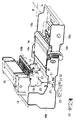
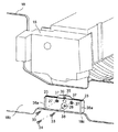
図2は、フレーム、定着ユニット、位置調整板及び位置調整部材の位置関係を示す分解斜視図である。なお、この図において、搬送ユニット12は省略している。フレーム18は上方が開放されたトレイ形状の板金組品であり、用紙搬送方向(図中矢印Aの方向)に対して直交する方向(同図中矢印Bの方向)で対面する側壁18a,18bを有し、両側壁の周囲には外側に所定の高さで突出する外郭18cが形成されている。定着ユニット15の下部には、用紙搬送方向に対して直交する方向で、フレーム18の幅よりも狭い距離で対面する一対の取付壁15b,15cが設けられている。
FIG. 2 is an exploded perspective view showing a positional relationship among the frame, the fixing unit, the position adjustment plate, and the position adjustment member. In this figure, the
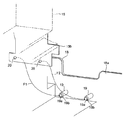
図3は、フレーム18の一方の側壁18aの定着ユニット15装着部近傍を示す拡大斜視図である。フレーム18の一方の側壁18aには、フレーム18の内側に突出する一対の突起棒19が突設されている。突起棒19の先端部19aは、境界に段差面19bを有するように、同軸に細径に形成されている。一方、定着ユニット15の装着状態でフレーム18の側壁18aと対面することになる定着ユニット15の取付壁15bには、フレーム18の突起棒19の先端部19aが挿入される一対の穴20が貫設されている。定着ユニット15装着時に取付壁15bの穴20が移動する経路を示すため、同図に矢印F1及び矢印F2を補助的に示している。
FIG. 3 is an enlarged perspective view showing the vicinity of the
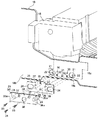
図4は、フレーム18の他方の側壁18bの定着ユニット15装着部近傍を示す拡大斜視図である。フレーム18の他方の側壁18bには、一対の長円形の長穴21が貫設され、一対の長穴21の間にネジ33の先が螺号されることなく嵌る一対の丸孔30が上方に貫設され、ネジ34が螺号されるネジ孔31が下方に一つが貫設されている。また、一対の丸孔30の下方には、一対の凹部32が型押しで設けられている。一方、定着ユニット15の装着状態でフレーム18の側壁18bと対面する定着ユニット15の取付壁15cには、一対の穴22が貫設されている。この穴22には、後述する位置調整板23に設けられた突起棒26の先端部26aが挿入される。
FIG. 4 is an enlarged perspective view showing the vicinity of the fixing
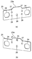
図6は、位置調整板の正面斜視図(a)及び背面斜視図(b)である。位置調整板23は、スチール製の板材であり、上縁の中央部には台形状に出っ張った突起面23aが形成されている。長円形の一対の長穴24を有する。一対の長穴24の間には、ネジ33(図4参照)が螺号される一対のネジ孔27が上方に貫設され、ネジ34(同図参照)が螺号されるネジ孔28が一つ貫設されている。また、図6(a)に示すように、位置調整板23の表面には、一対のネジ孔27の下方に、フレーム18に位置調整板23を仮止めするときに使用する一対の凸部29が凸設されている。また、図6(b)に示すように、位置調整板23の背面には、突起面23aの中央部に縦溝を等間隔で入れ、目盛り35を設けている。
FIG. 6 is a front perspective view (a) and a rear perspective view (b) of the position adjusting plate. The
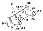
図7は、位置調整部材の正面斜視図である。位置調整部材25は、スチール製の基板36と、該基板36の表面側に突出する一対の突起棒26とから構成されている。基板36の両端は、裏面側へ曲げ加工してツマミ36aを形成している。基板36には、一対の突起棒26の間にネジ33(図4参照)が挿通される一対の長孔37が上方に貫設され、ネジ34(同図参照)が螺号されることなく収まる大穴38が一つ貫設されている。突起棒26の先端部26aは、境界に段差面26bを有するように、同軸に細径に形成されている。また、基板36の背面には、上縁の中心を示す指針39が設けられている。
FIG. 7 is a front perspective view of the position adjusting member. The
上記構成により、定着ユニット15の装着手順について説明する。まず、図3に示すように、前記定着ユニット15の前記フレーム18に対する位置決めを行う。すなわち、用紙搬送方向に対して直交する方向の一端側で、同図矢印F1及び矢印F2に示すように、定着ユニット15の穴20をフレーム18の突起棒19に合わせるように定着ユニット15をフレーム18内で側壁18aに向けて動かすと、突起棒19の先端部19aが穴20に挿入されるとともに、突起棒19の段差面19bが定着ユニット15の取付壁15bに当接し、定着ユニット15を転写ユニット14の用紙搬送方向の下流側の所定位置に設置することができる。
A procedure for mounting the fixing
そして、用紙搬送方向に対して直交する方向の他端側で、フレーム18に位置調整板23を仮止めする。すなわち、図4に示すように、位置調整板23の正面をフレーム18の側壁18bの外面に密着させるとともに、位置調整板23の長穴24とフレーム18の長穴21を合致させるように位置調整板23を押さえながら動かすと、1カ所で位置調整板23の凸部29とフレーム18の凹部32とが強固に凹凸嵌合し、また、位置調整板23の下縁がフレーム18の外郭18cの段部に当接することにより、脱落することなく所定位置に強固に仮止めすることができる。
Then, the
そして、位置調整板23の長穴24に、位置調整部材25の突起棒26を挿通するように位置調整部材25を押さえながら動かすと、突起棒26の先端部26aが定着ユニット15の穴22に挿入されるとともに、突起棒26の段差面26bが定着ユニット15の取付壁15cに当接するので、図5に示すように、最初は位置調整部材25の指針39を位置調整板23の目盛り35の中心に合わせ、この位置でネジ33及びネジ34を用いて定着ユニット15をフレーム18に装着する。このとき、手順としてはまず、一対のネジ33を位置調整部材25の長孔37に通して位置調整板23のネジ孔27に螺号し、位置調整部材25を位置調整板23に対して固定する。この状態では、ネジ33の先はフレーム18の側壁18bの丸孔30に嵌っているだけであるので、次いでネジ34を大穴38の内側から位置調整板23のネジ孔28とフレーム18のネジ孔31に螺合することにより、位置調整板23をフレーム18に固定する。これにより、位置調整部材25も位置調整板23を介してフレーム18に固定され、定着ユニット15がフレーム18に装着される。
Then, when the
そして、フレーム18を筐体10a内にスライド収納し、画像形成装置に実際に用紙の通紙を行い、目視にて転写ベルト14aによって搬送される用紙が定着ユニット15の定着ローラ対15aに通紙される時の通紙角度を確認する。もし、用紙幅方向で用紙のどちらかの端部が先に定着ローラ対15aに巻き込まれるような場合は、用紙の両端で均等に通紙されるように定着ユニット15の装着位置を調整する。すなわち、フレーム18を筐体10aから引き出し、位置調整板23及び位置調整部材25を止めているネジ33及びネジ34をすべて外し、位置調整部材25のツマミ36aを持って指針39を目盛り35の中心から左右どちらかに必要量だけ摺動させ、この位置で再びネジ33,34を用いて定着ユニット15をフレーム18に装着する。上記の作業を繰り返すことで、定着ユニット15の装着位置を適切な位置に容易に調整することができる。
Then, the
また、一度このようにして定着ユニット15の装着位置の調整をすれば、ネジ34を一本外すだけで、位置調整板23と位置調整部材25とを一体で取り外し、定着ユニット15を取り外すことができるため、サービス時などに定着ユニット15を元の位置に労せず装着することができる。
Further, once the mounting position of the fixing
本発明は、画像形成装置における定着装置の位置調整方法及びその装置に利用することができる。 The present invention can be used for a fixing device position adjusting method and apparatus in an image forming apparatus.
10 画像形成装置
10a 筐体
11 給紙装置
12 搬送ユニット
12a 用紙搬送ローラ
12b レジストローラ
13 画像形成部
13a 感光体ドラム
13b 帯電器
13c 現像器
13b 帯電体
13d クリーニング装置
14 転写ユニット
14a 転写ベルト
14b 転写ローラ
15 定着ユニット
15a 定着ローラ対
15b,15c 取付壁
16 排紙ローラ対
17 両面印刷ユニット
17a 反転経路
18 フレーム
18a,18b フレーム側壁
18c 外郭
19 突起棒
19a 先端部
19b 段差面
20 穴
21 長穴
22 穴
23 位置調整板
23a 突起面
24 長穴
25 位置調整部材
26 突起棒
26a 先端部
26b 段差面
27,28 ネジ孔
29 凸部
30 丸孔
31 ネジ孔
32 凹部
33,34 ネジ
36 基板
36a ツマミ
37 長孔
38 大穴
39 指針
DESCRIPTION OF
Claims (3)
用紙搬送方向に対して直交する方向の一端側で前記フレームの突起棒と前記定着装置の一端面の穴とを嵌合させて前記定着装置の前記フレームに対する位置決めをし、他端側で前記フレームの長穴と該フレームに仮止めされた前記位置調整板の長穴に前記位置調整部材の突起棒を挿通するとともに、該突起棒と前記定着装置の他端面の穴とを嵌合させて、前記位置調整部材を前記位置調整板上で用紙搬送方向に摺動させることにより、前記定着装置の前記転写ベルトに対する位置を調整することを特徴とする定着装置の位置調整装置。 A frame on which a transfer belt for transporting paper is mounted; a projecting bar projecting on one of the side walls facing in a direction perpendicular to the paper transport direction of the frame; and one end surface of the fixing device A hole into which the protruding bar is fitted, a position adjusting member having the protruding bar, and the other side of the side wall facing the sheet in the direction orthogonal to the paper transport direction of the frame are inserted through the protruding bar of the position adjusting member. A position adjusting plate having a slot which is temporarily fixed to the outside of the frame and into which a protrusion rod of the position adjusting member is inserted at a position corresponding to the slot of the frame, and the other end surface of the fixing device And a hole into which the protruding rod of the position adjusting member is fitted,
The projecting rod of the frame and a hole on one end surface of the fixing device are fitted on one end side in a direction orthogonal to the sheet conveying direction to position the fixing device with respect to the frame, and the frame on the other end side. And inserting the protrusion rod of the position adjustment member into the elongated hole of the position adjustment plate temporarily fixed to the frame, and fitting the protrusion rod and the hole on the other end surface of the fixing device, A position adjusting device for a fixing device, wherein the position of the fixing device relative to the transfer belt is adjusted by sliding the position adjusting member on the position adjusting plate in a sheet conveying direction.
Priority Applications (1)
| Application Number | Priority Date | Filing Date | Title |
|---|---|---|---|
| JP2004109595A JP4480446B2 (en) | 2004-04-02 | 2004-04-02 | Fixing device position adjustment device |
Applications Claiming Priority (1)
| Application Number | Priority Date | Filing Date | Title |
|---|---|---|---|
| JP2004109595A JP4480446B2 (en) | 2004-04-02 | 2004-04-02 | Fixing device position adjustment device |
Publications (2)
| Publication Number | Publication Date |
|---|---|
| JP2005292612A true JP2005292612A (en) | 2005-10-20 |
| JP4480446B2 JP4480446B2 (en) | 2010-06-16 |
Family
ID=35325576
Family Applications (1)
| Application Number | Title | Priority Date | Filing Date |
|---|---|---|---|
| JP2004109595A Expired - Fee Related JP4480446B2 (en) | 2004-04-02 | 2004-04-02 | Fixing device position adjustment device |
Country Status (1)
| Country | Link |
|---|---|
| JP (1) | JP4480446B2 (en) |
Cited By (14)
| Publication number | Priority date | Publication date | Assignee | Title |
|---|---|---|---|---|
| JP2007193087A (en) * | 2006-01-19 | 2007-08-02 | Ricoh Co Ltd | Image forming apparatus, fixing apparatus, and recording material conveyance direction correction method |
| JP2007328204A (en) * | 2006-06-08 | 2007-12-20 | Ricoh Co Ltd | Scanner holding device and image forming apparatus |
| JP2008268665A (en) * | 2007-04-23 | 2008-11-06 | Kyocera Mita Corp | Image forming apparatus |
| JP2008273646A (en) * | 2007-04-25 | 2008-11-13 | Kyocera Mita Corp | Paper carrying device and image forming device |
| JP2009042735A (en) * | 2007-03-28 | 2009-02-26 | Ricoh Co Ltd | Image forming apparatus, fixing unit supporting method of image forming apparatus, and fixing unit movement adjusting method |
| JP2009122246A (en) * | 2007-11-13 | 2009-06-04 | Ricoh Co Ltd | Image forming apparatus |
| JP2010054701A (en) * | 2008-08-27 | 2010-03-11 | Kyocera Mita Corp | Drive unit and image forming apparatus |
| JP2011008141A (en) * | 2009-06-29 | 2011-01-13 | Canon Inc | Image forming apparatus |
| JP2011016642A (en) * | 2009-07-10 | 2011-01-27 | Canon Inc | Image forming device |
| US8244168B2 (en) | 2007-06-25 | 2012-08-14 | Ricoh Company, Ltd. | Image forming apparatus with movable transfer device |
| JP2013127573A (en) * | 2011-12-19 | 2013-06-27 | Fuji Xerox Co Ltd | Fixing device and image forming apparatus |
| JP2014134624A (en) * | 2013-01-09 | 2014-07-24 | Ricoh Co Ltd | Fixing unit positioning apparatus and image forming apparatus |
| WO2015046621A1 (en) * | 2013-09-26 | 2015-04-02 | キヤノン株式会社 | Positioning member and image formation device |
| JP7438856B2 (en) | 2020-06-09 | 2024-02-27 | キヤノン株式会社 | Recording material cooling device, image forming device, and image forming system |
Citations (5)
| Publication number | Priority date | Publication date | Assignee | Title |
|---|---|---|---|---|
| JPH0428653U (en) * | 1990-06-29 | 1992-03-06 | ||
| JPH0535008A (en) * | 1990-10-15 | 1993-02-12 | Ricoh Co Ltd | Image forming device |
| JPH05188800A (en) * | 1992-01-14 | 1993-07-30 | Ricoh Co Ltd | Image forming device |
| JPH08171248A (en) * | 1994-10-20 | 1996-07-02 | Fuji Xerox Co Ltd | Image forming device provided with belt module and method for positioning belt module in image forming device |
| JP2002271052A (en) * | 2001-03-09 | 2002-09-20 | Ricoh Co Ltd | Adjustment mechanism for front door opening / closing force |
-
2004
- 2004-04-02 JP JP2004109595A patent/JP4480446B2/en not_active Expired - Fee Related
Patent Citations (5)
| Publication number | Priority date | Publication date | Assignee | Title |
|---|---|---|---|---|
| JPH0428653U (en) * | 1990-06-29 | 1992-03-06 | ||
| JPH0535008A (en) * | 1990-10-15 | 1993-02-12 | Ricoh Co Ltd | Image forming device |
| JPH05188800A (en) * | 1992-01-14 | 1993-07-30 | Ricoh Co Ltd | Image forming device |
| JPH08171248A (en) * | 1994-10-20 | 1996-07-02 | Fuji Xerox Co Ltd | Image forming device provided with belt module and method for positioning belt module in image forming device |
| JP2002271052A (en) * | 2001-03-09 | 2002-09-20 | Ricoh Co Ltd | Adjustment mechanism for front door opening / closing force |
Cited By (18)
| Publication number | Priority date | Publication date | Assignee | Title |
|---|---|---|---|---|
| JP2007193087A (en) * | 2006-01-19 | 2007-08-02 | Ricoh Co Ltd | Image forming apparatus, fixing apparatus, and recording material conveyance direction correction method |
| JP2007328204A (en) * | 2006-06-08 | 2007-12-20 | Ricoh Co Ltd | Scanner holding device and image forming apparatus |
| JP2009042735A (en) * | 2007-03-28 | 2009-02-26 | Ricoh Co Ltd | Image forming apparatus, fixing unit supporting method of image forming apparatus, and fixing unit movement adjusting method |
| JP2008268665A (en) * | 2007-04-23 | 2008-11-06 | Kyocera Mita Corp | Image forming apparatus |
| JP2008273646A (en) * | 2007-04-25 | 2008-11-13 | Kyocera Mita Corp | Paper carrying device and image forming device |
| US8244168B2 (en) | 2007-06-25 | 2012-08-14 | Ricoh Company, Ltd. | Image forming apparatus with movable transfer device |
| JP2009122246A (en) * | 2007-11-13 | 2009-06-04 | Ricoh Co Ltd | Image forming apparatus |
| JP2010054701A (en) * | 2008-08-27 | 2010-03-11 | Kyocera Mita Corp | Drive unit and image forming apparatus |
| US8406659B2 (en) | 2009-06-29 | 2013-03-26 | Canon Kabushiki Kaisha | Image forming apparatus |
| JP2011008141A (en) * | 2009-06-29 | 2011-01-13 | Canon Inc | Image forming apparatus |
| JP2011016642A (en) * | 2009-07-10 | 2011-01-27 | Canon Inc | Image forming device |
| JP2013127573A (en) * | 2011-12-19 | 2013-06-27 | Fuji Xerox Co Ltd | Fixing device and image forming apparatus |
| JP2014134624A (en) * | 2013-01-09 | 2014-07-24 | Ricoh Co Ltd | Fixing unit positioning apparatus and image forming apparatus |
| EP2755091A3 (en) * | 2013-01-09 | 2016-12-14 | Ricoh Company Ltd. | Fixing unit position-adjusting apparatus and image forming apparatus |
| WO2015046621A1 (en) * | 2013-09-26 | 2015-04-02 | キヤノン株式会社 | Positioning member and image formation device |
| JP2015087754A (en) * | 2013-09-26 | 2015-05-07 | キヤノン株式会社 | Positioning member and image forming apparatus |
| US9804555B2 (en) | 2013-09-26 | 2017-10-31 | Canon Kabushiki Kaisha | Positioning member and image forming apparatus |
| JP7438856B2 (en) | 2020-06-09 | 2024-02-27 | キヤノン株式会社 | Recording material cooling device, image forming device, and image forming system |
Also Published As
| Publication number | Publication date |
|---|---|
| JP4480446B2 (en) | 2010-06-16 |
Similar Documents
| Publication | Publication Date | Title |
|---|---|---|
| JP5751048B2 (en) | Image forming apparatus | |
| JP5741255B2 (en) | Image forming apparatus | |
| JP4480446B2 (en) | Fixing device position adjustment device | |
| CN104284044B (en) | Hinge, image read-out and image processing system with the Hinge | |
| CN101627343A (en) | Process cartridge and image forming apparatus | |
| US8805234B2 (en) | Photosensitive unit and image forming apparatus | |
| CN115509101B (en) | Image forming device | |
| JP6323381B2 (en) | Sheet conveying apparatus and image forming apparatus provided with sheet conveying apparatus | |
| EP2755091B1 (en) | Fixing unit position-adjusting apparatus and image forming apparatus | |
| JP5206781B2 (en) | Process unit and development unit | |
| US8472842B2 (en) | Image forming device including process unit provided with handle | |
| US20070018387A1 (en) | Sheet conveying device | |
| JP2006282381A (en) | Image forming device | |
| JP4956280B2 (en) | Paper feeding cassette and image forming apparatus | |
| JP2001109211A (en) | Image forming device and attaching unit | |
| JPH08190283A (en) | Image forming device and transfer device therefor | |
| JP4063275B2 (en) | Paper cassette | |
| JP5565484B2 (en) | Process unit and development unit | |
| JPH08190284A (en) | Image forming device and transfer device therefor | |
| JP2002068492A (en) | Paper feeder and image forming apparatus | |
| JP2022038383A (en) | Image forming apparatus | |
| JP2007225829A (en) | Image forming apparatus | |
| JP5097236B2 (en) | Image forming apparatus | |
| US20060222403A1 (en) | Image forming apparatus | |
| JP2020197607A (en) | Image forming apparatus |
Legal Events
| Date | Code | Title | Description |
|---|---|---|---|
| A621 | Written request for application examination |
Free format text: JAPANESE INTERMEDIATE CODE: A621 Effective date: 20070327 |
|
| A977 | Report on retrieval |
Free format text: JAPANESE INTERMEDIATE CODE: A971007 Effective date: 20091112 |
|
| A131 | Notification of reasons for refusal |
Free format text: JAPANESE INTERMEDIATE CODE: A131 Effective date: 20091124 |
|
| A521 | Request for written amendment filed |
Free format text: JAPANESE INTERMEDIATE CODE: A523 Effective date: 20100120 |
|
| TRDD | Decision of grant or rejection written | ||
| A01 | Written decision to grant a patent or to grant a registration (utility model) |
Free format text: JAPANESE INTERMEDIATE CODE: A01 Effective date: 20100316 |
|
| A01 | Written decision to grant a patent or to grant a registration (utility model) |
Free format text: JAPANESE INTERMEDIATE CODE: A01 |
|
| A61 | First payment of annual fees (during grant procedure) |
Free format text: JAPANESE INTERMEDIATE CODE: A61 Effective date: 20100316 |
|
| FPAY | Renewal fee payment (event date is renewal date of database) |
Free format text: PAYMENT UNTIL: 20130326 Year of fee payment: 3 |
|
| R150 | Certificate of patent or registration of utility model |
Ref document number: 4480446 Country of ref document: JP Free format text: JAPANESE INTERMEDIATE CODE: R150 Free format text: JAPANESE INTERMEDIATE CODE: R150 |
|
| FPAY | Renewal fee payment (event date is renewal date of database) |
Free format text: PAYMENT UNTIL: 20130326 Year of fee payment: 3 |
|
| S533 | Written request for registration of change of name |
Free format text: JAPANESE INTERMEDIATE CODE: R313533 |
|
| FPAY | Renewal fee payment (event date is renewal date of database) |
Free format text: PAYMENT UNTIL: 20130326 Year of fee payment: 3 |
|
| R350 | Written notification of registration of transfer |
Free format text: JAPANESE INTERMEDIATE CODE: R350 |
|
| FPAY | Renewal fee payment (event date is renewal date of database) |
Free format text: PAYMENT UNTIL: 20130326 Year of fee payment: 3 |
|
| RD03 | Notification of appointment of power of attorney |
Free format text: JAPANESE INTERMEDIATE CODE: R3D03 |
|
| LAPS | Cancellation because of no payment of annual fees |