JP2005292567A5 - - Google Patents
Download PDFInfo
- Publication number
- JP2005292567A5 JP2005292567A5 JP2004109088A JP2004109088A JP2005292567A5 JP 2005292567 A5 JP2005292567 A5 JP 2005292567A5 JP 2004109088 A JP2004109088 A JP 2004109088A JP 2004109088 A JP2004109088 A JP 2004109088A JP 2005292567 A5 JP2005292567 A5 JP 2005292567A5
- Authority
- JP
- Japan
- Prior art keywords
- image
- fixing
- separation
- recording material
- image heating
- Prior art date
- Legal status (The legal status is an assumption and is not a legal conclusion. Google has not performed a legal analysis and makes no representation as to the accuracy of the status listed.)
- Granted
Links
- 238000000926 separation method Methods 0.000 claims description 159
- 238000010438 heat treatment Methods 0.000 claims description 118
- 239000000463 material Substances 0.000 claims description 87
- 210000000078 claw Anatomy 0.000 description 77
- 238000012546 transfer Methods 0.000 description 46
- 229910052751 metal Inorganic materials 0.000 description 23
- 239000002184 metal Substances 0.000 description 23
- 238000000034 method Methods 0.000 description 12
- 229920001971 elastomer Polymers 0.000 description 10
- 229910052736 halogen Inorganic materials 0.000 description 9
- 150000002367 halogens Chemical class 0.000 description 9
- 230000008569 process Effects 0.000 description 8
- 238000011144 upstream manufacturing Methods 0.000 description 7
- 230000000052 comparative effect Effects 0.000 description 6
- 238000010586 diagram Methods 0.000 description 5
- 229920002379 silicone rubber Polymers 0.000 description 5
- 239000004945 silicone rubber Substances 0.000 description 5
- 230000007246 mechanism Effects 0.000 description 4
- 238000002844 melting Methods 0.000 description 4
- 230000008018 melting Effects 0.000 description 4
- 239000003086 colorant Substances 0.000 description 3
- 150000002739 metals Chemical class 0.000 description 3
- 230000002093 peripheral effect Effects 0.000 description 3
- 239000011347 resin Substances 0.000 description 3
- 229920005989 resin Polymers 0.000 description 3
- 238000004804 winding Methods 0.000 description 3
- YCKRFDGAMUMZLT-UHFFFAOYSA-N Fluorine atom Chemical compound [F] YCKRFDGAMUMZLT-UHFFFAOYSA-N 0.000 description 2
- PXHVJJICTQNCMI-UHFFFAOYSA-N Nickel Chemical compound [Ni] PXHVJJICTQNCMI-UHFFFAOYSA-N 0.000 description 2
- 229910052774 Proactinium Inorganic materials 0.000 description 2
- 239000002131 composite material Substances 0.000 description 2
- 230000000694 effects Effects 0.000 description 2
- 229910052731 fluorine Inorganic materials 0.000 description 2
- 239000011737 fluorine Substances 0.000 description 2
- 229910052745 lead Inorganic materials 0.000 description 2
- 239000000843 powder Substances 0.000 description 2
- 125000006850 spacer group Chemical group 0.000 description 2
- 239000004642 Polyimide Substances 0.000 description 1
- 238000005299 abrasion Methods 0.000 description 1
- 238000013459 approach Methods 0.000 description 1
- 230000008901 benefit Effects 0.000 description 1
- 238000004140 cleaning Methods 0.000 description 1
- 239000011248 coating agent Substances 0.000 description 1
- 238000000576 coating method Methods 0.000 description 1
- 230000003111 delayed effect Effects 0.000 description 1
- 230000001419 dependent effect Effects 0.000 description 1
- 238000011161 development Methods 0.000 description 1
- 230000005684 electric field Effects 0.000 description 1
- 238000001704 evaporation Methods 0.000 description 1
- 238000002474 experimental method Methods 0.000 description 1
- 239000004744 fabric Substances 0.000 description 1
- 229920001973 fluoroelastomer Polymers 0.000 description 1
- 229920002313 fluoropolymer Polymers 0.000 description 1
- 239000004811 fluoropolymer Substances 0.000 description 1
- 230000004907 flux Effects 0.000 description 1
- 229910052742 iron Inorganic materials 0.000 description 1
- 239000007788 liquid Substances 0.000 description 1
- 238000004519 manufacturing process Methods 0.000 description 1
- 208000026721 nail disease Diseases 0.000 description 1
- 229910052759 nickel Inorganic materials 0.000 description 1
- 239000004745 nonwoven fabric Substances 0.000 description 1
- 239000002245 particle Substances 0.000 description 1
- 229920001721 polyimide Polymers 0.000 description 1
- 238000003825 pressing Methods 0.000 description 1
- 238000012545 processing Methods 0.000 description 1
- 238000001454 recorded image Methods 0.000 description 1
- 238000003303 reheating Methods 0.000 description 1
- 230000004044 response Effects 0.000 description 1
- 229920002545 silicone oil Polymers 0.000 description 1
- XLYOFNOQVPJJNP-UHFFFAOYSA-N water Substances O XLYOFNOQVPJJNP-UHFFFAOYSA-N 0.000 description 1
Description
本発明は、例えば複写機、ファクシミリ、プリンタ等の画像形成装置において、記録材に形成担持させた未定着画像を定着させる画像加熱装置に関する。 The present invention relates to an image heating apparatus for fixing an unfixed image formed and supported on a recording material in an image forming apparatus such as a copying machine, a facsimile machine, or a printer.
より詳しくは、記録材上の画像を加熱する第1の画像加熱手段と、この第1の画像加熱手段から記録材を分離させる第1の分離手段と、第1の画像加熱手段よりも記録材搬送方向下流側に設けられ第1の画像加熱手段にて加熱された記録材上の画像を加熱する第2の画像加熱手段と、この第2の画像加熱手段から記録材を分離させる第2の分離手段と、を有する画像加熱装置に関する。 More specifically, the first image heating means for heating the image on the recording material, the first separation means for separating the recording material from the first image heating means, and the recording material than the first image heating means. Second image heating means for heating the image on the recording material provided on the downstream side in the transport direction and heated by the first image heating means, and second for separating the recording material from the second image heating means. And an image heating apparatus having separation means .
電子写真プロセスを利用した複写機等の画像形成装置は、用紙(記録材)上に転写方式あるいは直接方式で形成された画像(未定着現像剤像)を加熱する画像加熱装置を備える。 An image forming apparatus such as a copying machine using an electrophotographic process includes an image heating apparatus that heats an image (unfixed developer image) formed on a sheet (recording material) by a transfer method or a direct method.
近年、画像加熱装置としては、通紙の高速化や高画質化に伴い複数個の画像加熱手段を備えるものが増えてきている(例えば、特許文献1参照)。 In recent years, as an image heating apparatus, an apparatus provided with a plurality of image heating means is increasing as the speed of paper passing and image quality increase (for example, see Patent Document 1).
これは、未定着画像を担持させた記録材に接して画像を加熱する画像加熱手段を記録材搬送方向に沿って複数個配列し、記録材を前記複数の画像加熱手段を順次に通過させて画像加熱するものである。 This is because a plurality of image heating means for heating an image in contact with a recording material carrying an unfixed image are arranged along the recording material conveyance direction, and the recording material is sequentially passed through the plurality of image heating means. The image is heated.
複数個の画像加熱手段をもつものの特徴としては、記録材搬送方向最上流側の第一の画像加熱手段に未定着画像を担持させた記録材を一度通して画像を加熱定着させ、この記録材を更に下流側の第二の画像加熱手段に通して画像を再加熱させるなどの工夫がなされている。一般的には、第一の画像加熱手段においてはある程度の定着性を確保し、第二の画像加熱手段においては、高画質(高グロス)を目指したものが多い。特に、画像の光沢度は記録材の搬送方向の下流側の第二の画像加熱手段による影響が大きい。 A feature of the apparatus having a plurality of image heating means is that the recording material carrying an unfixed image is passed once through the first image heating means on the most upstream side in the recording material conveyance direction, and the image is heated and fixed. The image is further reheated by passing the image through a second image heating means on the downstream side. In general, the first image heating means ensures a certain degree of fixing property, and the second image heating means often aims for high image quality (high gloss). In particular, the glossiness of the image is greatly influenced by the second image heating means on the downstream side in the recording material conveyance direction.
このような画像加熱装置においても、記録材の一面目と二面目の画像を定着させる際の分離性を高めるために、各々の画像加熱手段に分離部材を設けることが有効である。 Also in such an image heating apparatus , it is effective to provide a separation member for each image heating means in order to improve the separation property when fixing the first and second image on the recording material.
ところで、分離爪を画像加熱手段に当接させると分離性を格段に高めることができるが、画像加熱手段の表面を傷つける問題、また、当接させる分離爪をレシプロ運動させることで傷を軽減することができるが、分離爪と画像表面がこすれることで画像加熱手段の表面性が一部かわることで、光沢むらを生ずる。従って、分離爪を設けることは、分離性の向上という利点と光沢むらという欠点を兼ね備えているものである。
しかし、上流側の画像加熱手段の分離部材と下流側の画像加熱手段の分離部材とを同構成にした場合には、下記の問題が生ずる。 However, when the upstream side image heating means separating member and the downstream side image heating means separating member have the same configuration, the following problems arise.
上流側の画像加熱手段は、完全な未定着画像と画像加熱手段とが接触し、溶融トナーと画像加熱手段間の付着力が強いため、分離能力を十分に確保する必要がある。一方、一度加熱された画像を再加熱する際には、分離性は上流側の画像加熱手段に比べて高くなることから、上流側の画像加熱手段に比べて分離能力を低くしても、十分な分離性を確保できる。 The upstream image heating means is in contact with the completely unfixed image and the image heating means, and the adhesion between the molten toner and the image heating means is strong. On the other hand, when the reheating once heated image, since it is higher than the image heating means separation of the upstream side, even with a lower separation capability as compared with the image heating means upstream, sufficient Secure separability.
一方で、画像の光沢度は、画像と接触する画像加熱手段の表面性に大きく依存することがしられている。これらを踏まえると、画像加熱手段の表面性に分離部材によりむらがある状態では、表面性のむらが画像の光沢度のむらに大きく影響を受ける結果となり、複数の画像加熱手段を設けることで、光沢度を上げるという効果が低減してしまう。 On the other hand, the glossiness of an image is greatly dependent on the surface property of the image heating means that comes into contact with the image . Considering these, in the state where the surface property of the image heating means is uneven due to the separation member, the surface property unevenness is greatly influenced by the unevenness of the glossiness of the image. The effect of raising the value is reduced.
従って、下流側の画像加熱手段に上流側の画像加熱手段の分離構成を採用すると、光沢むらを解消する為に、画像加熱手段の交換サイクルが短くなってしまう。 Therefore, by adopting the separate configuration of an image heating means upstream to the image heating means downstream, in order to eliminate the uneven gloss, replacement cycle of the image heating means is shortened.
上記の課題は、特にカラー画像の定着や高速、高生産性を目的とする画像加熱時に、安定した分離性を得る場合に問題となる。 The above-mentioned problem becomes a problem when obtaining a stable separation property, particularly when fixing a color image or heating an image for the purpose of high speed and high productivity.
本発明では、上述したような課題を解決し、カラー画像においても高速で高い生産性を得られる画像加熱装置を提供することを目的とする。 An object of the present invention is to solve the above-described problems and to provide an image heating apparatus capable of obtaining high productivity at high speed even for color images.
より具体的には、複数の画像加熱手段を設けられている構成において、分離性を向上させつつ、画像光沢むらを小さくできる画像加熱装置を提供することことを目的とする。 More specifically, an object of the present invention is to provide an image heating apparatus capable of reducing unevenness in image gloss while improving separability in a configuration provided with a plurality of image heating means .
以上の課題は、以下のような本発明によって解決される。 The above problems are solved by the present invention as follows.
(1)記録材上の画像を加熱する第1の画像加熱手段と、この第1の画像加熱手段から記録材を分離させる第1の分離手段と、第1の画像加熱手段よりも記録材搬送方向下流側に設けられ第1の画像加熱手段にて加熱された記録材上の画像を加熱する第2の画像加熱手段と、この第2の画像加熱手段から記録材を分離させる第2の分離手段と、を有する画像加熱装置において、第1の分離手段と第2の分離手段とでその分離方式を異ならせたことを特徴とする画像加熱装置。 (1) First image heating means for heating an image on the recording material, first separation means for separating the recording material from the first image heating means, and recording material conveyance more than the first image heating means A second image heating means for heating an image on the recording material provided on the downstream side in the direction and heated by the first image heating means, and a second separation for separating the recording material from the second image heating means. An image heating apparatus comprising: a first separation unit and a second separation unit, wherein the separation method is different between the first separation unit and the second separation unit .
(2)上記第1の分離手段は上記第1の画像加熱手段に接触した状態で記録材を分離する構成とされ、上記第2の分離手段は上記第2の画像加熱手段に非接触の状態で記録材を分離する構成とされていることを特徴とする(1)の画像加熱装置。 (2) The first separation unit is configured to separate the recording material in contact with the first image heating unit, and the second separation unit is in a non-contact state with the second image heating unit. (1) The image heating apparatus according to (1), wherein the recording material is separated.
(3)上記第1の分離手段と上記第2の分離手段はそれぞれ上記第1の画像加熱手段と上記第2の画像加熱手段に接触した状態で記録材を分離する構成とされ、且つ、上記第2の分離手段の上記第2の画像加熱手段への接触圧が上記第1の分離手段の上記第1の画像加熱手段への接触圧よりも小さいことを特徴とする(1)の画像加熱装置。 (3) The first separation unit and the second separation unit are configured to separate the recording material in contact with the first image heating unit and the second image heating unit, respectively, and The image heating according to (1), wherein a contact pressure of the second separation unit to the second image heating unit is smaller than a contact pressure of the first separation unit to the first image heating unit. apparatus.
(4)上記第1の分離手段と上記第2の分離手段は記録材の画像を担持した側とは反対側の面に当接可能な分離部材をそれぞれ有していることを特徴とする(3)の画像加熱装置。 (4) The first separation means and the second separation means each have a separation member capable of abutting against a surface of the recording material opposite to the side carrying the image ( 3) The image heating apparatus.
以上の本発明によれば、複数の画像加熱手段が設けられている構成において、長期にわたって画像光沢むらを小さくできると共に分離性を確保することができる。 According to the present invention as described above, in the configuration in which a plurality of image heating means are provided, it is possible to reduce the unevenness of image gloss over a long period of time and to ensure separation.
また、カラー画像を形成する画像形成装置において、2次色や3次色のなどトナーの載り量がアップした場合や、薄紙や高湿環境下の様に記録材のコシが無くなる場合や、画像加熱手段表面の温度が低下した場合や、記録材の先端に画像が存在する場合でも、良好な排紙性能を確保し、高速定着と高い生産性を得ることが可能となる。 In the image forming apparatus, 2 Tsugishoku and or if the tertiary color toner amount such as is up, if the stiffness of the recording material as the lower thin and high humidity environment is eliminated and to form a color image, the image Even when the temperature of the surface of the heating means is lowered or an image is present at the leading edge of the recording material, it is possible to ensure good paper discharge performance and to obtain high-speed fixing and high productivity.
以下に、実施例を挙げて、本発明をより具体的に説明する。なお、これら実施例は、本発明における最良の実施の形態の一例ではあるものの、本発明はこれら実施例により限定されるものではない。 Hereinafter, the present invention will be described more specifically with reference to examples. Although these examples are examples of the best mode of the present invention, the present invention is not limited to these examples.
(1)画像形成装置例
図1は画像形成装置の一例の概略構成模型図である。本例の画像形成装置は転写式電子写真プロセスを用いた、タンデムタイプのカラーレーザプリンタである。
(1) Example of Image Forming Apparatus FIG. 1 is a schematic configuration model diagram of an example of an image forming apparatus. The image forming apparatus of this example is a tandem type color laser printer using a transfer type electrophotographic process.
この画像形成装置内には第1、第2、第3、第4の4つの画像形成部Pa、Pb、Pc、Pdが併設され、各々異なった色のトナー像が潜像、現像、転写のプロセスを経て形成される。 The image forming apparatus includes four image forming portions Pa, Pb, Pc, and Pd that are first, second, third, and fourth, and toner images of different colors are used for latent images, development, and transfer, respectively. Formed through a process.
各画像形成部Pa、Pb、Pc、Pdは、それぞれ専用の像担持体、本例では電子写真感光ドラム3a、3b、3c、3dを具備し、各感光ドラム3a、3b、3c、3d上に各色のトナー像が形成される。各感光ドラム3a、3b、3c、3dに隣接して中間転写体(中間転写ベルト)130が設置され、感光ドラム3a、3b、3c、3d上に形成された各色のトナー像が、中間転写体130上に1次転写され、2次転写部で記録材P上に転写される。さらにトナー像が転写された記録材Pは、画像加熱装置9に導入されてトナー像が定着されて記録画像形成物として装置外の排紙トレイ18に排出される。画像加熱装置9は第1の定着装置9Aと第2の定着装置9Bとの2つの定着装置を有する。この画像加熱装置9については後述する。 Each of the image forming portions Pa, Pb, Pc, and Pd includes a dedicated image carrier, in this example, the electrophotographic photosensitive drums 3a, 3b, 3c, and 3d, on the photosensitive drums 3a, 3b, 3c, and 3d. A toner image of each color is formed. An intermediate transfer member (intermediate transfer belt) 130 is installed adjacent to each of the photosensitive drums 3a, 3b, 3c, and 3d, and the toner images of the respective colors formed on the photosensitive drums 3a, 3b, 3c, and 3d are transferred to the intermediate transfer member. Primary transfer onto 130 and transfer onto the recording material P at the secondary transfer portion. Further, the recording material P onto which the toner image has been transferred is introduced into the image heating device 9, where the toner image is fixed, and is discharged as a recorded image formed product onto a paper discharge tray 18 outside the device. The image heating device 9 has two fixing devices, a first fixing device 9A and a second fixing device 9B. The image heating device 9 will be described later.
感光ドラム3a、3b、3c、3dの外周には、それぞれドラム帯電器2a、2b、2c、2d、現像器1a、1b、1c、1d、1次転写帯電器24a、24b、24c、24d及びクリーナ4a、4b、4c、4dが設けられ、装置の上方部にはさらにレーザスキャナ5a、5b、5c、5dが設置されている。 Drum chargers 2a, 2b, 2c, and 2d, developing devices 1a, 1b, 1c, and 1d, primary transfer chargers 24a, 24b, 24c, and 24d, and a cleaner are disposed on the outer periphery of the photosensitive drums 3a, 3b, 3c, and 3d, respectively. 4a, 4b, 4c, and 4d are provided, and laser scanners 5a, 5b, 5c, and 5d are further provided above the apparatus.
感光ドラム3a、3b、3c、3dは矢印の反時計方向に回転駆動され、その周面がドラム帯電器2a、2b、2c、2dにより所定の極性・電位に一様に1次帯電される。その各感光ドラム3a、3b、3c、3dの一様帯電面に対してレーザスキャナ5a、5b、5c、5dから出力される、画像信号に応じて変調されたレーザ光La、Lb、Lc、Ldによる走査露光がなされて、各感光ドラム3a、3b、3c、3d上に画像信号に応じた潜像が形成される。すなわち、レーザスキャナ5a、5b、5c、5dは、それぞれ、光源装置、ポリゴンミラー等が設置されていて、光源装置から発せられたレーザ光をポリゴンミラーを回転して走査し、その走査光の光束を反射ミラーによって偏向し、fθレンズにより感光ドラム3a、3b、3c、3dの母線上に集光して露光することにより、感光ドラム3a、3b、3c、3d上に画像信号に応じた潜像が形成される。 The photosensitive drums 3a, 3b, 3c, and 3d are rotationally driven in the counterclockwise direction indicated by the arrow, and the peripheral surfaces thereof are uniformly primary charged to a predetermined polarity and potential by the drum chargers 2a, 2b, 2c, and 2d. Laser beams La, Lb, Lc, and Ld modulated in accordance with image signals output from the laser scanners 5a, 5b, 5c, and 5d to the uniformly charged surfaces of the photosensitive drums 3a, 3b, 3c, and 3d. As a result of the scanning exposure, a latent image corresponding to the image signal is formed on each of the photosensitive drums 3a, 3b, 3c, and 3d. That is, each of the laser scanners 5a, 5b, 5c, and 5d is provided with a light source device, a polygon mirror, and the like, scans the laser light emitted from the light source device by rotating the polygon mirror, and the light flux of the scanning light Is deflected by a reflection mirror, condensed on the buses of the photosensitive drums 3a, 3b, 3c, and 3d by an fθ lens and exposed, whereby a latent image corresponding to the image signal is formed on the photosensitive drums 3a, 3b, 3c, and 3d. Is formed.
現像器1a、1b、1c、1dには、現像剤としてそれぞれシアン、マゼンタ、イエロー及びブラックのトナーが供給装置6a、6b、6c、6dにより所定量充填されている。現像器1a、1b、1c、1dは、それぞれ感光ドラム3a、3b、3c、3d上の潜像を現像して、シアントナー像、マゼンタトナー像、イエロートナー像及びブラックトナー像として可視化する。 The developing devices 1a, 1b, 1c, and 1d are filled with a predetermined amount of cyan, magenta, yellow, and black toners as developers by the supply devices 6a, 6b, 6c, and 6d, respectively. The developing devices 1a, 1b, 1c, and 1d develop the latent images on the photosensitive drums 3a, 3b, 3c, and 3d, respectively, and visualize them as cyan toner images, magenta toner images, yellow toner images, and black toner images.
中間転写体130は3本の並行ローラ13、14、15間に懸回張設したエンドレスベルト部材であり、矢示の時計方向に感光ドラム3a、3b、3c、3dと同じ周速度をもって回転駆動されている。 The intermediate transfer member 130 is an endless belt member suspended around three parallel rollers 13, 14, 15, and is driven to rotate at the same peripheral speed as the photosensitive drums 3 a, 3 b, 3 c, 3 d in the clockwise direction indicated by the arrow. Has been.
第1の画像形成部Paの感光ドラム3a上に形成担持された上記第1色のイエロートナー画像は、感光ドラム3aと中間転写体130とのニップ部を通過する過程で、中間転写体130に印加される1次転写バイアスにより形成される電界と圧力により、中間転写体130の外周面に1次転写されていく。 The yellow toner image of the first color formed and supported on the photosensitive drum 3 a of the first image forming portion Pa passes through the nip portion between the photosensitive drum 3 a and the intermediate transfer member 130 and is transferred to the intermediate transfer member 130. Primary transfer is performed on the outer peripheral surface of the intermediate transfer body 130 by the electric field and pressure formed by the applied primary transfer bias.
以下、同様に、第2、第3、第4の画像形成部Pb、Pc、Pdの感光ドラム3b、3c、3d上に形成担持された、第2色のマゼンタトナー画像、第3色のシアントナー画像、第4色のブラックトナー画像が順次に中間転写体130上に重畳転写され、中間転写体130上に目的のカラー画像に対応した合成カラートナー画像が形成される。 Hereinafter, similarly, the second color magenta toner image and the third color cyan formed and supported on the photosensitive drums 3b, 3c, and 3d of the second, third, and fourth image forming portions Pb, Pc, and Pd. The toner image and the black toner image of the fourth color are sequentially superimposed and transferred onto the intermediate transfer member 130, and a composite color toner image corresponding to the target color image is formed on the intermediate transfer member 130.
11は2次転写ローラであり、中間転写体130を懸回張設させた3本のローラ13・14・15のうちのローラ14に対して中間転写体130を挟ませて圧接させて中間転写体130との間に2次転写ニップ部を形成している。 Reference numeral 11 denotes a secondary transfer roller. The intermediate transfer body 130 is sandwiched and pressed against the roller 14 out of the three rollers 13, 14, and 15, which are stretched around the intermediate transfer body 130. A secondary transfer nip portion is formed with the body 130.
一方、給紙カセット10から記録材Pが1枚分離給紙されて、シートパス16、シートパス17、レジストローラ12、転写前ガイドを通過して中間転写体130と2次転写ローラ11との当接ニップである2次転写ニップ部に所定のタイミングで給送され、同時に2次転写バイアスがバイアス電源からに印加される。これにより、中間転写体130上に重畳転写された合成カラートナー画像の記録材Pへの一括2次転写がなされる。 On the other hand, the recording material P is separated and fed from the sheet feeding cassette 10 and passes through the sheet path 16, the sheet path 17, the registration roller 12, and the pre-transfer guide, and the intermediate transfer body 130 and the secondary transfer roller 11. A secondary transfer bias is fed from a bias power source to the secondary transfer nip portion, which is a contact nip, at a predetermined timing. As a result, the secondary transfer of the combined color toner image superimposed and transferred onto the intermediate transfer body 130 onto the recording material P is performed.
2次転写ニップ部にて合成カラートナー画像の転写を受けた記録材Pは中間転写体130から分離されて、像加熱装置9導入され、先ず第1の定着装置9Aに、次いで第2の定着装置9Bに導入され、該直列2つの定着装置9Aと9Bを順次に通ることで記録材にトナー像が熱圧定着される。 The recording material P that has received the transfer of the composite color toner image at the secondary transfer nip is separated from the intermediate transfer body 130 and introduced into the image heating device 9, first to the first fixing device 9 A, and then to the second fixing. The toner image is fixed to the recording material by being introduced into the device 9B and sequentially passing through the two fixing devices 9A and 9B in series.
1次転写が終了した感光ドラム3a、3b、3c、3dは、それぞれのクリーナ4a、4b、4c、4dにより転写残トナーをクリーニング、除去され、引き続き次の潜像の形成以下に備えられる。 After the primary transfer, the photosensitive drums 3a, 3b, 3c, and 3d are cleaned and removed of the transfer residual toner by the respective cleaners 4a, 4b, 4c, and 4d, and are continuously prepared to form the next latent image.
転写ベルト130上に残留したトナー及びその他の異物は、転写ベルト130の表面にクリーニングウエブ(不織布)19を当接して、拭い取るようにしている。 The toner and other foreign matters remaining on the transfer belt 130 are wiped off by contacting a cleaning web (nonwoven fabric) 19 with the surface of the transfer belt 130.
両面コピーモードが選択されている場合には、像加熱装置9の第2の定着装置9Bを出た第1面側画像形成済みの記録材Pがフラッパ20により再循環搬送機構側のシートパス21側に導入され、さらにスイッチバックシートパス22内に入り、次いで該シートパス22から引き出されて再搬送シートパス23に誘導され、該シートパス23から、シートパス17、レジストローラ12、転写前ガイドを通過して中間転写体130と2次転写ローラ11との当接ニップである2次転写ニップ部に表裏反転状態で所定のタイミングで再導入される。これにより、記録材Pの第2面側に対して、中間転写体130上のトナー画像の2次転写がなされる。2次転写ニップ部にて第2面に対するトナー画像の2次転写を受けた記録材Pは中間転写体130から分離されて第1と第2の定着装置9A・9Bへ再導入され、トナー画像の定着処理を受けて両面コピーとして装置外の排紙トレイ18に排出される。 When the double-sided copy mode is selected, the recording material P on which the first-surface-side image has been formed that has exited the second fixing device 9B of the image heating device 9 is fed by the flapper 20 to the sheet path 21 on the recirculation conveyance mechanism side. Is further introduced into the switchback sheet path 22 and then pulled out from the sheet path 22 and guided to the re-conveying sheet path 23. From the sheet path 23, the sheet path 17, the registration roller 12, and the pre-transfer guide And is re-introduced into the secondary transfer nip portion, which is a contact nip between the intermediate transfer body 130 and the secondary transfer roller 11, at a predetermined timing in a state where the front and back sides are reversed. Thereby, the secondary transfer of the toner image on the intermediate transfer body 130 is performed on the second surface side of the recording material P. The recording material P that has received the secondary transfer of the toner image onto the second surface at the secondary transfer nip is separated from the intermediate transfer member 130 and re-introduced into the first and second fixing devices 9A and 9B. In response to the fixing process, the two-sided copy is discharged to a discharge tray 18 outside the apparatus.
(2)画像加熱装置9
図2は第1と第2の直列2つの定着装置9A・9Bを有する画像加熱装置9の部分の拡大図である。この第1と第2の定着装置9A・9Bは記録材搬送方向に関して、第1の定着装置9Aは上流側の定着装置であり、第2の定着装置9Bは下流側の定着装置となる。
(2) Image heating device 9
FIG. 2 is an enlarged view of a portion of the image heating device 9 having the first and second fixing devices 9A and 9B in series. Regarding the first and second fixing devices 9A and 9B, the first fixing device 9A is an upstream fixing device and the second fixing device 9B is a downstream fixing device in the recording material conveyance direction.
本実施例における第1と第2の定着装置9A・9Bは共に熱ローラ方式の定着装置である。すなわち、各定着装置は9A・9Bにおいて、51と52は像加熱体(定着部材)としての定着ローラと加圧ローラである。加圧ローラ52は定着ローラ51に対して圧接してニップ部(定着ニップ部)Nを形成する。定着ローラ51は不図示の駆動系により矢印の時計方向に回転駆動される。加圧ローラ52はこの定着ローラ51の回転に従動して回転する。
ここで、第1の定着装置9Aの定着ローラ51と加圧ローラ52が、記録材上の画像を加熱する第1の画像加熱手段である。また、第2の定着装置9Aの定着ローラ51と加圧ローラ52が、第1の画像加熱手段51・52よりも記録材搬送方向下流側に設けられ第1の画像加熱手段51・52にて加熱された記録材上の画像を加熱する第2の画像加熱手段である。
Both the first and second fixing devices 9A and 9B in this embodiment are heat roller type fixing devices. That is, in each fixing device 9A and 9B, 51 and 52 are a fixing roller and a pressure roller as an image heating body (fixing member). The pressure roller 52 is pressed against the fixing roller 51 to form a nip portion (fixing nip portion) N. The fixing roller 51 is rotationally driven in a clockwise direction indicated by an arrow by a drive system (not shown). The pressure roller 52 rotates following the rotation of the fixing roller 51.
Here, the fixing roller 51 and the pressure roller 52 of the first fixing device 9A are the first image heating means for heating the image on the recording material. Further, the fixing roller 51 and the pressure roller 52 of the second fixing device 9A are provided on the downstream side in the recording material conveyance direction with respect to the first image heating means 51 and 52. This is a second image heating means for heating the image on the heated recording material.
より具体的には、定着ローラ51は、外径φ75.0mmのAlからなる中空芯金51a上に、弾性層51bとしてゴム硬度20°(JIS−A1kg加重)のシリコーンゴムを、第1の定着装置9Aでは厚さ2.5mm、第2の定着装置9Bでは厚さ1.5mmで成形し、さらにその表面に離型性層51cとして50μm厚みのPFAチューブを被覆した外径約φ80mmのものを用いた。 More specifically, in the fixing roller 51, a silicone rubber having a rubber hardness of 20 ° (JIS-A1 kg load) is formed as the elastic layer 51b on the hollow core metal 51a made of Al having an outer diameter of φ75.0 mm as the first fixing. The apparatus 9A is formed with a thickness of 2.5 mm, and the second fixing apparatus 9B is formed with a thickness of 1.5 mm, and the surface thereof is coated with a 50 μm-thick PFA tube as a release layer 51c, and has an outer diameter of about φ80 mm. Using.
定着ローラ51は、内部に加熱源としてハロゲンヒータ53を有し、このハロゲンヒータ53に対して不図示の電源部から電力供給がなされて、該ハロゲンヒータ53の発熱により定着ローラ51が内部加熱される。その定着ローラ51の表面温度が該定着ローラ51に接触または非接触に配設された温度検知体としてのサーミスタ等の温度センサー54により検出され、その検出温度情報が不図示の温度制御回路に入力する。温度制御回路は温度センサー54から入力する検知温度情報が所定の制御温度に維持されるように電源部からハロゲンヒータ53への電力供給を制御する。本実施例においては、第1の定着装置9Aにおける定着ローラ51の表面温度は180℃、第2の定着装置9Bにおける定着ローラ51の表面温度は200℃に維持されるように温調している。 The fixing roller 51 has a halogen heater 53 as a heating source inside, and power is supplied to the halogen heater 53 from a power supply unit (not shown), and the fixing roller 51 is internally heated by the heat generated by the halogen heater 53. The The surface temperature of the fixing roller 51 is detected by a temperature sensor 54 such as a thermistor as a temperature detector arranged in contact with or not in contact with the fixing roller 51, and the detected temperature information is input to a temperature control circuit (not shown). To do. The temperature control circuit controls power supply from the power supply unit to the halogen heater 53 so that the detected temperature information input from the temperature sensor 54 is maintained at a predetermined control temperature. In this embodiment, the surface temperature of the fixing roller 51 in the first fixing device 9A is adjusted to 180 ° C., and the surface temperature of the fixing roller 51 in the second fixing device 9B is adjusted to 200 ° C. .
ここで、カラー用の定着装置では定着ローラ51の表面離型性層51cの代わりにシリコーンオイルを含浸させたシリコーンゴム層やフッ素ゴム層を用いたものもあり、本発明はこれらゴム層を用いた定着装置においても適用可能なものである。 Here, some color fixing devices use a silicone rubber layer or a fluorine rubber layer impregnated with silicone oil instead of the surface releasable layer 51c of the fixing roller 51, and the present invention uses these rubber layers. It can also be applied to a conventional fixing device.
加圧ローラ52は、外径φ75mmのAlからなる中空芯金52aの周囲に、ゴム硬度16°(JIS−A1kg加重)のシリコーンゴムからなる弾性層52bを、第1の定着装置9Aでは厚さ2.0mm、第2の定着装置9Bでは厚さ1.5mmで成形し、さらにその表面に離型性層52cとして50μm厚みのPFAチューブを被覆した外径約φ78mmのものを用いた。 In the first fixing device 9A, the pressure roller 52 has an elastic layer 52b made of silicone rubber having a rubber hardness of 16 ° (JIS-A1 kg load) around a hollow cored bar 52a made of Al having an outer diameter of φ75 mm. In the second fixing device 9B, 2.0 mm was formed with a thickness of 1.5 mm, and the surface thereof was coated with a 50 μm-thick PFA tube as the releasable layer 52 c and an outer diameter of about φ78 mm was used.
本実施例においてはこの加圧ローラ52にもその内部に加熱源としてハロゲンヒータ53を配設してあり、このハロゲンヒータ53に対して不図示の電源部から電力供給がなされて、該ハロゲンヒータ53の発熱により加圧ローラ52が内部加熱される。その加圧ローラ52の表面温度が該加圧ローラ52に接触または非接触に配設されたサーミスタ等の温度センサー54により検出され、その検出温度情報が不図示の温度制御回路に入力する。温度制御回路は温度センサー54から入力する検知温度情報が所定の制御温度に維持されるように電源部からハロゲンヒータ53への電力供給を制御する。本実施例においては、第1の定着装置9Aにおける加圧ローラ52も、第2の定着装置9Bにおける加圧ローラ52も、共に表面温度140℃に維持されるように温調している。 In this embodiment, the pressure roller 52 is also provided with a halogen heater 53 as a heating source therein, and electric power is supplied to the halogen heater 53 from a power supply unit (not shown). The pressure roller 52 is internally heated by the heat generated by 53. The surface temperature of the pressure roller 52 is detected by a temperature sensor 54 such as a thermistor disposed in contact with or not in contact with the pressure roller 52, and the detected temperature information is input to a temperature control circuit (not shown). The temperature control circuit controls power supply from the power supply unit to the halogen heater 53 so that the detected temperature information input from the temperature sensor 54 is maintained at a predetermined control temperature. In this embodiment, both the pressure roller 52 in the first fixing device 9A and the pressure roller 52 in the second fixing device 9B are temperature-controlled so that the surface temperature is maintained at 140 ° C.
加圧ローラ52は、第1の定着装置9Aにおいては定着ローラ51に対して総圧700Nで加圧して、約10mm幅の定着ニップ部Nを形成させている。また第2の定着装置9Bにおいては定着ローラ51に対して総圧1000Nで加圧して、約5mm幅の定着ニップ部Nを形成させている。 In the first fixing device 9A, the pressure roller 52 presses the fixing roller 51 with a total pressure of 700 N to form a fixing nip portion N having a width of about 10 mm. In the second fixing device 9B, the fixing roller 51 is pressed at a total pressure of 1000 N to form a fixing nip portion N having a width of about 5 mm.
55と56は記録材分離部材であり、定着ニップ部Nの記録材出口側近傍において、定着ローラ51側と加圧ローラ52側とにそれぞれ配設してある。
ここで、第1の定着装置9Aの第1の画像加熱手段である定着ローラ51と加圧ローラ52に対する記録材分離部材55・56が第1の画像加熱手段から記録材を分離する第1の分離手段である。また、第2の定着装置9Bの第2の画像加熱手段である定着ローラ51と加圧ローラ52に対する記録材分離部材55・56が第2の画像加熱手段から記録材を分離する第2の分離手段である。
以下、第1及び第2の定着装置9Aと9Bにおいて、定着ローラ51側の記録材分離部材55を上分離爪、加圧ローラ52側の記録材分離部材56を下分離爪と記す。
Reference numerals 55 and 56 denote recording material separating members, which are disposed on the fixing roller 51 side and the pressure roller 52 side in the vicinity of the recording material outlet side of the fixing nip N, respectively.
Here, the recording material separating members 55 and 56 for the fixing roller 51 and the pressure roller 52, which are the first image heating means of the first fixing device 9A, separate the recording material from the first image heating means. Separation means. Further, the second separation for separating the recording material from the second image heating means by the recording material separating members 55 and 56 for the fixing roller 51 and the pressure roller 52 as the second image heating means of the second fixing device 9B. Means.
Hereinafter, in the first and second fixing devices 9A and 9B, the recording material separation member 55 on the fixing roller 51 side is referred to as an upper separation claw, and the recording material separation member 56 on the pressure roller 52 side is referred to as a lower separation claw.
そして、上記の第1及び第2の定着装置9A・9Bの定着ローラ51及び加圧ローラ52が回転駆動され、且つ定着ローラ51及び加圧ローラ52が所定の表面温度に加熱温調されている状態において、第1の定着装置9Aの定着ニップ部Nに作像部側から送られた、未定着トナー像tを担持した記録材Pが入口側ガイド57に案内されて導入される。導入記録材Pは定着ニップ部Nで挟持搬送されながら定着ニップ部Nでの熱と圧力によりトナー像の定着処理を受ける。定着ニップ部Nを出た記録材Pは上下の分離爪55・56で定着ローラ51または加圧ローラ52の面から分離され、出口側ガイド58と橋渡しガイド59に案内されて第2の定着装置9Bに導入され、入口側ガイド57に案内されて第2の定着装置9Bの定着ニップ部Nに導入される。導入記録材Pは定着ニップ部Nで挟持搬送されながらトナー像の再度の熱圧定着処理を受ける。定着ニップ部Nを出た記録材Pは上下の分離爪55・56で定着ローラ51または加圧ローラ52の面から分離され、出口側ガイド58でガイドされて第2の定着装置9Bから出る。 Then, the fixing roller 51 and the pressure roller 52 of the first and second fixing devices 9A and 9B are rotationally driven, and the fixing roller 51 and the pressure roller 52 are heated to a predetermined surface temperature. In this state, the recording material P carrying the unfixed toner image t sent from the image forming unit side to the fixing nip portion N of the first fixing device 9A is guided by the inlet side guide 57 and introduced. The introduced recording material P is subjected to a fixing process of the toner image by heat and pressure at the fixing nip N while being nipped and conveyed at the fixing nip N. The recording material P that has exited the fixing nip N is separated from the surface of the fixing roller 51 or the pressure roller 52 by the upper and lower separation claws 55 and 56, and is guided by the outlet side guide 58 and the bridging guide 59 to be the second fixing device. 9B, guided by the inlet side guide 57, and introduced into the fixing nip N of the second fixing device 9B. The introduced recording material P is subjected to a heat pressure fixing process for the toner image again while being nipped and conveyed at the fixing nip portion N. The recording material P exiting the fixing nip portion N is separated from the surface of the fixing roller 51 or the pressure roller 52 by the upper and lower separation claws 55 and 56, guided by the outlet side guide 58, and exits from the second fixing device 9B.
第1の定着装置9Aと第2の定着装置9Bとにおける上下分離爪55・56は、第1の定着装置9Aと第2の定着装置9Bとで異なる構成にしてある。即ち、第1の分離手段と第2の分離手段とでその分離方式を異ならせている。以下、これについて詳述する。 The upper and lower separation claws 55 and 56 in the first fixing device 9A and the second fixing device 9B are configured differently in the first fixing device 9A and the second fixing device 9B. That is, the separation method is different between the first separation means and the second separation means. This will be described in detail below.
1)第1の定着装置9A側の分離爪構成
図3は図2の第1の定着装置9A側の上下分離爪55・56部分の拡大図、図4は上分離爪55の構造説明図である。上分離爪55は図4のように先端が鋭利な爪形状をしており、不図示の定着ユニットフレームに固定されたホルダー802に軸803を中心に回動自由に支持させ、バネ801により該上分離爪55をその先端が定着ローラ51の表面に当接する方向に回動付勢させて、上分離爪先端を加圧力0.01〜0.03N程度の加圧力で定着ローラ51の表面に当接させている。この上分離爪55の表面は、定着ローラ51との摺動性を上げるために、フッ素樹脂加工がなされている事が好ましい。上分離爪55の幅は10mm程度とし、定着ローラ51表面を傷つけにくいようになっている。更に好ましくは、爪の当接位置が時間的に変わるようなレシプロ機構を備えていると良い。
1) Separation Claw Configuration on the First Fixing Device 9A Side FIG. 3 is an enlarged view of the upper and lower separation claws 55 and 56 on the first fixing device 9A side in FIG. 2, and FIG. is there. The upper separation claw 55 has a claw shape with a sharp tip as shown in FIG. 4, and is supported by a holder 802 fixed to a fixing unit frame (not shown) so as to freely rotate about a shaft 803, and the spring 801 The upper separation claw 55 is rotated and biased in a direction in which the front end of the upper separation claw comes into contact with the surface of the fixing roller 51, and the upper separation claw tip is applied to the surface of the fixing roller 51 with a pressure of about 0.01 to 0.03N. It is in contact. The surface of the upper separation claw 55 is preferably subjected to fluororesin processing in order to improve the slidability with the fixing roller 51. The width of the upper separation claw 55 is about 10 mm so that the surface of the fixing roller 51 is hardly damaged. More preferably, a reciprocating mechanism is provided so that the contact position of the nail changes with time.
上分離爪55は、記録材の画像濃度が濃い場合や、プリント環境が高湿度状態で記録材のコシが無い場合や、記録材が薄紙でコシが無い場合や、定着ローラ51の表面温度が低下して充分なトナー溶融を期待できない場合においても、記録材が定着ローラ51に巻きつく不具合を防止し、確実に第2の定着装置9Bへと搬送するように作用する。 The upper separation claw 55 has a surface temperature of the fixing roller 51 when the image density of the recording material is high, when the printing environment is high humidity and the recording material is not stiff, when the recording material is thin paper and stiff. Even when the toner cannot be expected to sufficiently melt the toner, it prevents the recording material from being wound around the fixing roller 51 and acts to reliably convey it to the second fixing device 9B.
下分離爪56も上分離爪55と同様の材料および構成をとり、加圧ローラ52の表面に当接している。下分離爪56は、両面プリント時において、2面目の画像濃度が濃い場合においても、記録材が加圧ローラに巻きつく不具合を防止し、確実に第2の定着装置9Bへと搬送するように作用する。 The lower separation claw 56 also has the same material and configuration as the upper separation claw 55 and is in contact with the surface of the pressure roller 52. The lower separation claw 56 prevents the recording material from being wound around the pressure roller even when the image density of the second surface is high during double-sided printing, and reliably conveys it to the second fixing device 9B. Works.
図5に定着ローラ51及び加圧ローラ52の長手方向からみた上分離爪55および下分離爪56の配置を示す。上分離爪55および下分離爪55はそれぞれ定着ローラ51及び加圧ローラ52の長手方向に6箇所配置されている。
このように、第1の定着装置9Aにおける第1の画像加熱手段51・52に対する第1の分離手段55・56は第1の画像加熱手段51・52に接触した状態で記録材を分離する構成とされている。
FIG. 5 shows the arrangement of the upper separation claw 55 and the lower separation claw 56 as seen from the longitudinal direction of the fixing roller 51 and the pressure roller 52. The upper separation claw 55 and the lower separation claw 55 are arranged at six locations in the longitudinal direction of the fixing roller 51 and the pressure roller 52, respectively.
In this way, the first separating means 55 and 56 for the first image heating means 51 and 52 in the first fixing device 9A separate the recording material in contact with the first image heating means 51 and 52. It is said that.
2)第2の定着装置9B側の分離爪構成
図6は図2の第2の定着装置9B側の上下分離爪55・56部分の拡大図である。第2の定着装置9B側の上分離爪55は上記の第1の定着装置9A側の上分離爪55と異なり、加圧構成は無く、定着フレームに固定されて、定着ローラ51に当接せず非接触に配置されている。上分離爪51の先端は、定着ローラ51の表面と0.5mm〜2.0mmのギャップαで工場出荷時に位置調整されて配置される。
2) Separation Claw Configuration on the Second Fixing Device 9B Side FIG. 6 is an enlarged view of the upper and lower separation claws 55 and 56 on the second fixing device 9B side in FIG. Unlike the above-described upper separation claw 55 on the first fixing device 9A side, the upper separation claw 55 on the second fixing device 9B side does not have a pressure configuration, and is fixed to the fixing frame and brought into contact with the fixing roller 51. It is arranged without contact. The tip of the upper separation claw 51 is positioned and adjusted at the time of shipment from the surface of the fixing roller 51 with a gap α of 0.5 mm to 2.0 mm.
下分離爪56も上記の上分離爪55と同構成をとり、加圧ローラ52に当接せず非接触に配置されている。 The lower separation claw 56 also has the same configuration as the upper separation claw 55 described above, and is disposed in a non-contact manner without contacting the pressure roller 52.
第2の定着装置9Bにおいても、上記上下の非接触分離爪55・56を第1の定着装置9Aの場合の図5と同様に配置した。
このように、第2の定着装置9Bにおける第2の画像加熱手段51・52に対する第2の分離手段55・56は第2の画像加熱手段51・52に非接触の状態で記録材を分離する構成とされている。
Also in the second fixing device 9B, the upper and lower non-contact separation claws 55 and 56 are arranged in the same manner as in FIG. 5 in the case of the first fixing device 9A.
In this way, the second separating means 55 and 56 for the second image heating means 51 and 52 in the second fixing device 9B separate the recording material in a non-contact state with the second image heating means 51 and 52. It is configured.
第2の定着装置9B側に分離部材を配置しないと、画像濃度、上下のローラ温度のバランス、記録材中の水分量、記録材のコシなどのバラツキにより第2の定着装置9B側での排紙方向が変わるため、安定した紙搬送性が得られない。実際に第2の定着装置9B側分離部材を設けない場合では、カールした紙が定着ユニットとローラの間に入り、ジャムが発生してしまった。 If a separating member is not arranged on the second fixing device 9B side, the discharge on the second fixing device 9B side is caused by variations in image density, upper and lower roller temperature balance, moisture content in the recording material, stiffness of the recording material, and the like. Since the paper direction changes, stable paper transportability cannot be obtained. In the case where the second fixing device 9B side separation member is not actually provided, the curled paper enters between the fixing unit and the roller, and a jam occurs.
本実施例のように、樹脂を母体とするトナーを、熱ローラ対によって加熱、加圧、搬送する熱ローラ対タイプの定着装置では、未定着トナーを熱溶融する過程で、トナー樹脂の粘性がアップし、定着ローラとの親和力がアップしてしまう。その際に、プリント環境が高湿度状態で記録材のコシが無い場合や、記録材が薄紙でコシが無い場合では、トナーと定着ローラの親和力が、紙のコシと紙搬送による引き離し力に勝り、定着ローラ51に巻きつく不具合が発生してしまう。また、連続プリント時など、定着ローラ51の表面温度が低下してしまい、充分なトナー溶融を期待できない場合においても、記録材が定着ローラ51に巻きつく不具合が発生してしまう。定着巻きつきが発生すると、ジャムとなってしまうため、プリント動作を停止して、ユーザーに定着部の巻きつき紙の処理と、機内に残されたジャム紙の処理を行わなければならず、操作性と生産性が著しく低下してしまう。 As in this embodiment, in a heat roller pair type fixing device that heats, pressurizes, and conveys toner based on a resin by a heat roller pair, the viscosity of the toner resin is reduced in the process of thermally melting the unfixed toner. Will increase the affinity with the fixing roller. At that time, if the printing environment is high humidity and the recording material is not stiff, or if the recording material is thin and stiff, the affinity between the toner and the fixing roller is superior to the paper stiffness and the separation force due to paper conveyance. As a result, a problem of winding around the fixing roller 51 occurs. In addition, when the surface temperature of the fixing roller 51 is lowered during continuous printing or the like and sufficient toner melting cannot be expected, a problem that the recording material is wound around the fixing roller 51 occurs. When fixing wrapping occurs, jamming occurs, so the printing operation must be stopped and the user must process the wrapping paper in the fixing unit and the remaining jammed paper in the machine. Productivity and productivity are significantly reduced.
一方で、定着ローラに分離爪を当接させると、定着ローラ表面との摺動によって軽微な摺動傷が発生する。また、排出直後の画像が爪に擦れる事による光沢ムラが発生してしまう。これらの問題を解決するために、定着ローラ表面にオイルを染込ませた布(ウェブ)を当接させることで摺動性をアップする、あるいは、溶けにくい硬いトナーを用いて画像光沢を抑えることで、爪との擦れによる光沢ムラを目立たなくする方法がある。 On the other hand, when the separation claw is brought into contact with the fixing roller, slight sliding scratches are generated due to sliding with the surface of the fixing roller. Further, gloss unevenness occurs due to the image immediately after being rubbed against the nail. In order to solve these problems, improve the slidability by bringing a cloth (web) soaked with oil on the surface of the fixing roller, or suppress the image gloss by using hard toner that does not melt easily. Thus, there is a method of making the uneven glossiness due to rubbing with the nails inconspicuous.
しかし、これらの方法を用いても本質的な解決にはなっておらず、爪部での光沢ムラを抑えつつ光沢度の高い画像を得ることは難しい。 However, even if these methods are used, it is not an essential solution, and it is difficult to obtain an image with high glossiness while suppressing uneven glossiness at the nail portion.
本実施例では、上記のように、第1の定着装置9Aには分離部材として上下分離爪55・56を接触配置し、第2の定着装置9Bには分離部材として上下分離爪55・56を非接触に配置している。 In this embodiment, as described above, the first fixing device 9A is provided with the upper and lower separation claws 55 and 56 as contact members, and the second fixing device 9B is provided with the upper and lower separation claws 55 and 56 as the separation members. Arranged non-contact.
以下の表1に、本発明の効果を比較するために行った比較実験として、第2の定着装置9Bは無しにして、第1の定着装置9Aのみの構成の場合(比較例1:第1定着後)、及び比較例1の構成で分離爪を非接触に配置した場合(比較例2:第1爪非接触)、本実施例の場合における排紙性能、光沢ムラ、寿命を比較した結果を示す。 In Table 1 below, as a comparative experiment conducted for comparing the effects of the present invention, the second fixing device 9B is omitted, and only the first fixing device 9A is used (Comparative Example 1: First). After fixing), and when the separation claw is arranged in a non-contact manner in the configuration of Comparative Example 1 (Comparative Example 2: first claw non-contact), the result of comparing the paper discharge performance, gloss unevenness, and life in this example Indicates.
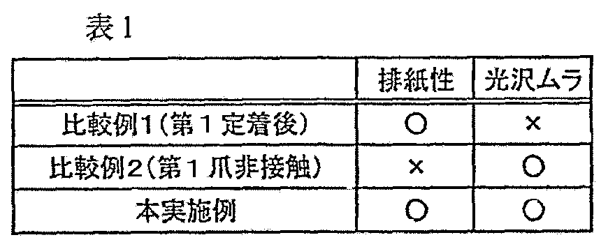
比較例1では、分離爪が接触式であるため、定着ローラ巻つきは発生せず良好な排紙性能を得たが、画像が爪に擦れた光沢ムラが発生してしまった。比較例2では、薄紙や画像濃度の高い画像において定着ローラ巻きつきが発生してしまった。本実施例では良好な排紙性を示しつつ、光沢ムラの無い良好な画像を得た。 In Comparative Example 1, since the separation claw is a contact type, winding of the fixing roller does not occur and good paper discharge performance is obtained. However, gloss unevenness occurs because the image is rubbed against the nail. In Comparative Example 2, the fixing roller was wound on a thin paper or an image having a high image density. In this example, a good image without gloss unevenness was obtained while showing good paper discharge performance.
このメカニズムは以下の様に想定される。すなわち、定着前の画像は記録材上に粉体として未定着のトナーが積層されており、トナーとトナーの間には空気が介入している。図7に定着前の画像tの断面イメージを模式的に示す。 This mechanism is assumed as follows. That is, an unfixed toner is laminated as a powder on a recording material in an image before fixing, and air intervenes between the toner. FIG. 7 schematically shows a cross-sectional image of the image t before fixing.
一方で、第1の定着装置9Aにて定着後(第1定着後)の画像は、記録材上の粉体トナーが一度熱溶融されることで、トナー間の空気が排出される。図8に第1定着後の画像tの断面イメージを模式的に示す。 On the other hand, in the image after being fixed by the first fixing device 9A (after the first fixing), the powder toner on the recording material is once melted by heat, whereby the air between the toners is discharged. FIG. 8 schematically shows a cross-sectional image of the image t after the first fixing.
実際に本実施例では、粒径7ミクロンのトナーを3色重ねて転写しており、そのトナー高さは21ミクロン程度となっているが、第1定着後のトナー高さは、12ミクロン程度となっていた。通常未定着トナー画像の約30%〜50%程度は空間であり、空気が混入している。この様なトナー層に混入した空気は、断熱層として作用するため、トナー層内の熱伝導性を極めて悪くする。一方で、定着後のトナーは溶融によって空間が埋められるために空気を含まず、トナー同士が結着しているため熱伝導性が良い。 Actually, in this embodiment, three colors of toner having a particle size of 7 microns are transferred and the toner height is about 21 microns, but the toner height after the first fixing is about 12 microns. It was. Usually, about 30% to 50% of the unfixed toner image is space and air is mixed therein. Since air mixed in such a toner layer acts as a heat insulating layer, the thermal conductivity in the toner layer is extremely deteriorated. On the other hand, the toner after fixing does not contain air because the space is filled by melting, and the toner is bound to each other, so that the heat conductivity is good.
トナーの熱溶融が十分になされると、トナーの粘性が下がり、液体状の流動状態になり、トナーに内包されたWAX等の離型成分が効率よく作用し、良好な分離性能が得られる。一方でトナーの熱伝導性が悪いと、トナーに内包されたWAX等の離型成分が効率よく作用しにくい。さらに、トナーの溶融が遅れるために粘性が下がりにくく、定着ニップ部出口でも粘性が高く、定着ローラに巻きつきやすくなってしまう。 When the toner is sufficiently melted by heat, the viscosity of the toner is lowered and the toner is in a liquid flow state, and a release component such as WAX contained in the toner acts efficiently, and a good separation performance is obtained. On the other hand, if the thermal conductivity of the toner is poor, a mold release component such as WAX contained in the toner does not act efficiently. Further, since the melting of the toner is delayed, the viscosity is hardly lowered, and the viscosity is high even at the exit of the fixing nip portion, so that the toner is easily wound around the fixing roller.
また、一度定着されたトナー画像からは、トナーに内包されたWAX等の離型成分がトナー層表面に析出し膜を形成しているために、定着ローラとの親和性が低く、巻きつきが発生しにくい。 In addition, from the toner image once fixed, a release component such as WAX contained in the toner is deposited on the surface of the toner layer to form a film, so that the affinity with the fixing roller is low and the winding is not generated. Hard to occur.
その他、一度定着した記録材は水分が蒸発する事によってコシが強くなり、良好な分離性能が得られる。 In addition, once the recording material is fixed, the stiffness of the recording material is increased by evaporating the water, and good separation performance can be obtained.
また、第2の定着装置9Bによる二度目の定着(第2定着)でトナー表面を再度定着することによって、第1定着で発生した光沢ムラ等の画像表面の乱れを整え、良好な画像性を得ることが可能となる。 Further, by fixing the toner surface again by the second fixing (second fixing) by the second fixing device 9B, the image surface disturbance such as gloss unevenness generated by the first fixing is adjusted, and good image quality is obtained. Can be obtained.
以上のような想定メカニズムにより、本実施例の第2定着では分離爪を非接触に配置しても、第1定着以上の良好な排紙性をしめすことが可能となる。また、第1定着で発生した爪との擦れによる光沢ムラを、第2定着で2回定着することによって目立たなくすることが可能となる。また、第2定着では分離爪を非接触としているので、爪の摺動による削れ磨耗をなくし、寿命が第1定着よりも長くなる。 Due to the assumed mechanism as described above, in the second fixing of this embodiment, even if the separation claw is arranged in a non-contact manner, it is possible to show a good paper discharge property that is higher than that of the first fixing. Further, uneven gloss due to rubbing with the nail generated in the first fixing can be made inconspicuous by fixing twice in the second fixing. Further, since the separation claw is not contacted in the second fixing, the wear due to the sliding of the claw is eliminated, and the life is longer than that of the first fixing.
本実施例において画像形成装置は実施例1と同じ形態(図1)を用いた。本実施例においては第1の定着装置9Aは実施例1の第1の定着装置9Aと同じであるが、第2の定着装置9Bについては実施例1の第2の定着装置9Bにおける分離部材構成のみを変更した。 In this embodiment, the same image forming apparatus as that in Embodiment 1 (FIG. 1) is used. In the present embodiment, the first fixing device 9A is the same as the first fixing device 9A of the first embodiment, but the second fixing device 9B is a separating member configuration in the second fixing device 9B of the first embodiment. Only changed.
すなわち、本実施例においては第2の定着装置9Bの非接触の上下分離爪55・56をそれぞれ、図9〜図11のように、先端が鋭利な板金(以下、分離板金と記す)によって構成した。この上下分離板金55・56の表面はトナー離型性の良いフッ素樹脂加工がなされている。 That is, in this embodiment, the non-contacting upper and lower separation claws 55 and 56 of the second fixing device 9B are each constituted by a sheet metal having a sharp tip (hereinafter referred to as a separation sheet metal) as shown in FIGS. did. The surfaces of the upper and lower separation metal plates 55 and 56 are processed with a fluororesin having good toner releasability.
上下分離板金55・56はそれぞれ図10に示すように定着ローラ51及び加圧ローラ52の長手に渡って存在するガイドのような構成であり、一定の間隔(ギャップα)を保ち定着ローラ51及び加圧ローラ52に近接している。上下分離板金55・56の先端と定着ローラ51及び加圧ローラ52の表面とのギャップαは、分離板金の両端部のスペーサー821を定着ローラ51及び加圧ローラ52に突き当てる事で1.0mmに保たれる。 As shown in FIG. 10, the upper and lower separation sheet metals 55 and 56 are configured like guides that exist over the lengths of the fixing roller 51 and the pressure roller 52, respectively, and maintain a fixed interval (gap α). Close to the pressure roller 52. The gap α between the leading ends of the upper and lower separation sheet metals 55 and 56 and the surfaces of the fixing roller 51 and the pressure roller 52 is 1.0 mm by abutting the spacers 821 at both ends of the separation sheet metal against the fixing roller 51 and the pressure roller 52. To be kept.
具体的に図11は上分離板金55の配設構成を示すものであり、不図示の定着ユニットフレームに固定されたホルダー802に軸803を中心に回動自由に支持させ、バネ801により該上分離板金55をその先端が定着ローラ51に寄る方向に回動付勢させて上分離板金55の両端部のスペーサー821を定着ローラ51に突き当て状態にする事で上分離板金55の先端と定着ローラの表面との間にギャップαを形成させている。 Specifically, FIG. 11 shows an arrangement configuration of the upper separation sheet metal 55. A holder 802 fixed to a fixing unit frame (not shown) is supported to freely rotate about a shaft 803, and the upper member is supported by a spring 801. The separation sheet metal 55 is rotated and biased in a direction in which the front end thereof approaches the fixing roller 51, and the spacers 821 at both ends of the upper separation sheet metal 55 are brought into contact with the fixing roller 51 to fix the front end of the upper separation sheet metal 55. A gap α is formed between the roller surface.
下分離板金56も上記の上分離板金55と同様の構成をとり、加圧ローラ52の表面との間にギャップαを形成させている。 The lower separation sheet metal 56 has the same configuration as the upper separation sheet metal 55 described above, and a gap α is formed between the lower separation sheet metal 56 and the surface of the pressure roller 52.
分離板金55・56の先端と定着ローラ51及び加圧ローラ52の表面とのギャップαは、他の方法によっても保証する事が可能であるが、0.5mm〜2.0mmのギャップαで配置されるのが好ましい。 The gap α between the front ends of the separation metal plates 55 and 56 and the surfaces of the fixing roller 51 and the pressure roller 52 can be guaranteed by other methods, but is arranged with a gap α of 0.5 mm to 2.0 mm. It is preferred that
本実施例においても、実施例1と同様の排紙性をしめし、第1定着で発生した、接触分離爪55・56との擦れによる光沢ムラを目立たなくすることが可能となる。また、第2定着では分離爪(分離板金)55・56を非接触としているので、分離爪の摺動による削れ磨耗をなくし、寿命が第1定着よりも長くなる。 Also in the present embodiment, the same paper discharge performance as in the first embodiment is shown, and it is possible to make the gloss unevenness caused by rubbing with the contact separation claws 55 and 56 generated by the first fixing inconspicuous. Further, in the second fixing, the separation claws (separation sheet metals) 55 and 56 are not in contact with each other, so that wear due to sliding of the separation claws is eliminated and the life is longer than that of the first fixing.
本実施例において画像形成装置は実施例1と同じ形態(図1)を用いた。本実施例においては第2の定着装置9Bは実施例1の第2の定着装置9Bと同じであるが、第1の定着装置9Aについては実施例1の第1の定着装置9Aにおける分離部材構成のみを変更した。 In this embodiment, the same image forming apparatus as that in Embodiment 1 (FIG. 1) is used. In the present embodiment, the second fixing device 9B is the same as the second fixing device 9B in the first embodiment, but the first fixing device 9A is a separating member configuration in the first fixing device 9A in the first embodiment. Only changed.
本実施例では、定着ローラ51の弾性層51bに低硬度ゴムを用いる事によって、定着ローラ51の硬度が加圧ローラ52の硬度よりも低い構成を用いている。 In this embodiment, a configuration is used in which the hardness of the fixing roller 51 is lower than the hardness of the pressure roller 52 by using low-hardness rubber for the elastic layer 51 b of the fixing roller 51.
定着ローラ51の構成として、以下の構成を用いた。 As the configuration of the fixing roller 51, the following configuration was used.
・ゴム厚・・・・・・2.5mm
・表層フッ素樹脂・・50μm厚被膜
・表面実効硬度・・・69°(Asker−C1kg加重)
・ゴムピース硬度・・10°(JIS−A1kg加重)
また、加圧ローラ52の構成として、以下の構成を用いた。
・ Rubber thickness ... 2.5mm
・ Surface fluororesin ・ ・ 50μm thick coating ・ Effective surface hardness ・ ・ ・ 69 ° (Asker-C1kg load)
・ Rubber piece hardness ・ ・ 10 ° (JIS-A1kg load)
Further, the following configuration was used as the configuration of the pressure roller 52.
・ゴム厚・・・ 2.0mm
・表層フッ素樹脂・・50μm厚被膜
・表面実効硬度・・・75°(Asker−C1kg加重)
・ゴムピース硬度・・16°(JIS−A1kg加重)
上記の構成においては、記録材の定着ニップ部Nからの排紙方向が下向きとなるために、定着ローラ51側の上分離爪55を当接させ無くても良好な分離性能を得ることが可能である。
・ Rubber thickness ... 2.0mm
・ Surface fluoropolymer ・ ・ 50μm thick film ・ Effective surface hardness ・ ・ ・ 75 ° (Asker-C1kg load)
・ Rubber piece hardness ・ ・ 16 ° (JIS-A1kg load)
In the above-described configuration, since the recording material is discharged from the fixing nip portion N in the downward direction, it is possible to obtain a good separation performance without contacting the upper separation claw 55 on the fixing roller 51 side. It is.
そこで本実施例では、図12のように、第1の定着装置9Aにおいて、上分離爪55には実施例2と同じ非接触分離板金55(図9〜図11)を用いている。一方で、両面プリント時には記録材Pが加圧ローラ52に巻きつく恐れがあるために下分離爪56には実施例1と同じ接触分離爪56を用いて良好な搬送性を得ている。 Therefore, in this embodiment, as shown in FIG. 12, in the first fixing device 9A, the same non-contact separation sheet metal 55 (FIGS. 9 to 11) as that of the second embodiment is used for the upper separation claw 55. On the other hand, since the recording material P may be wound around the pressure roller 52 during double-sided printing, the same contact separation claw 56 as in the first embodiment is used for the lower separation claw 56 to obtain good transportability.
この様な構成の第1の定着装置9Aと、実施例1と同じ構成の第2の定着装置9Bとを用いることによって、実施例1、2と同等の結果を得た。 By using the first fixing device 9A having such a configuration and the second fixing device 9B having the same configuration as that of the first embodiment, results equivalent to those of the first and second embodiments were obtained.
本実施例において画像形成装置は実施例1と同じ形態(図1)を用いた。本実施例においては第2の定着装置9Bは実施例1の第2の定着装置9Bと同じであるが、第1の定着装置9Aについては実施例1の第1の定着装置9Aとは異なる構成の定着装置にした。 In this embodiment, the same image forming apparatus as that in Embodiment 1 (FIG. 1) is used. In the present embodiment, the second fixing device 9B is the same as the second fixing device 9B of the first embodiment, but the first fixing device 9A is different from the first fixing device 9A of the first embodiment. The fixing device.
すなわち、本実施例では、第1の定着装置9Aに、図13のように、加熱ローラ52として、複数のローラ61〜63で張架されたエンドレスの加圧ベルト(定着ベルト)を用い、該加圧ベルト52を定着ローラ51に当接させ、加圧ベルト52の内側から、加圧パッド70および加圧パッド支持部71とを有した加圧部材で加圧ベルト52を定着ローラ51に加圧して定着ニップ部Nを形成したベルト定着構成の定着装置を用いている。 That is, in this embodiment, an endless pressure belt (fixing belt) stretched by a plurality of rollers 61 to 63 is used as the heating roller 52 as shown in FIG. The pressure belt 52 is brought into contact with the fixing roller 51, and the pressure belt 52 is applied to the fixing roller 51 from the inside of the pressure belt 52 with a pressure member having a pressure pad 70 and a pressure pad support portion 71. A fixing device having a belt fixing configuration in which a fixing nip portion N is formed by pressing is used.
定着ローラ51は矢印の時計方向に回転駆動される。加圧ベルト52は定着ローラ51の回転に従動して矢印の方向に回転する。 The fixing roller 51 is driven to rotate in the clockwise direction indicated by an arrow. The pressure belt 52 is rotated in the direction of the arrow following the rotation of the fixing roller 51.
定着ローラ51はAl、Feなどからなる芯金上にシリコーンゴムやフッ素ゴム等の弾性体層を被覆した構成になっている。加圧ベルト52はポリイミド等の樹脂またはニッケル等の金属からなる基材の表面にシリコーンゴムやフッ素ゴム等の弾性体層を被覆した構成になっている。 The fixing roller 51 has a configuration in which an elastic body layer such as silicone rubber or fluororubber is coated on a metal core made of Al, Fe or the like. The pressure belt 52 is configured such that the surface of a base material made of a resin such as polyimide or a metal such as nickel is coated with an elastic body layer such as silicone rubber or fluorine rubber.
定着ローラ51の内部には、ハロゲンランプ等のヒータ53が配設されている。また、定着ローラ51には不図示のサーミスタが接触または非接触に配設されており、温度調節回路を介してヒータ53への電圧を制御することにより定着ローラ51の表面の温度調節を行っている。 Inside the fixing roller 51, a heater 53 such as a halogen lamp is disposed. Further, a thermistor (not shown) is disposed in contact with or not in contact with the fixing roller 51, and the temperature of the surface of the fixing roller 51 is adjusted by controlling the voltage to the heater 53 through a temperature adjusting circuit. Yes.
加圧ベルト52を懸回させたローラ61〜63の内、ローラ61は金属からなる分離ローラであり、加圧ベルト52を介して定着ローラ51に食い込むように加圧することにより、定着ローラ51の弾性体を変形させ記録材Pを定着ローラ51表面から分離している。 Among the rollers 61 to 63 around which the pressure belt 52 is suspended, the roller 61 is a separation roller made of metal, and presses the fixing roller 51 through the pressure belt 52 so that the fixing roller 51 is pressed. The recording material P is separated from the surface of the fixing roller 51 by deforming the elastic body.
以上のように定着ローラ51とエンドレスの加圧ベルト52、加圧パッド70によって定着ニップ部Nを形成すると、加圧ベルト52により定着ローラ51の外周に巻きつくように幅広い定着ニップ部Nを形成することが可能となり、高速化に対して有利になる。 As described above, when the fixing nip N is formed by the fixing roller 51, the endless pressure belt 52, and the pressure pad 70, a wide fixing nip N is formed by the pressure belt 52 so as to wrap around the outer periphery of the fixing roller 51. This is advantageous for speeding up.
また、分離ローラ61を定着ローラ51の表面に食い込むように加圧することによって、実施例3よりも更に良好な分離性を示し、高速化に対して有利になる。 Further, by pressurizing the separation roller 61 so as to bite into the surface of the fixing roller 51, better separation performance than in the third embodiment is exhibited, which is advantageous for speeding up.
また従来のローラ対による定着装置の場合は、ニップ幅を広くとる場合は弾性体層を厚くしなければならず、省エネに対して不利になっていたのに対し、このような加圧ベルト52を用いた定着装置では、定着ローラ51の弾性体層を厚くすることなく広いニップを形成することが可能となるので弾性体層による熱伝達のロスを防ぐことが可能となり、省エネに有効である。 Further, in the case of a conventional fixing device using a pair of rollers, the elastic layer has to be thickened when the nip width is widened, which is disadvantageous for energy saving. In the fixing device using the toner, it is possible to form a wide nip without increasing the thickness of the elastic body layer of the fixing roller 51. Therefore, it is possible to prevent a heat transfer loss due to the elastic body layer, which is effective for energy saving. .
この様な構成においても、実施例3と同様に、定着ニップ部Nからの記録材Pの排紙方向が下向きとなるために、定着ローラ51側の上分離爪を当接させ無くても良好な分離性能を得ることが可能である。 Even in such a configuration, since the discharge direction of the recording material P from the fixing nip N is downward as in the third embodiment, it is not necessary to contact the upper separation claw on the fixing roller 51 side. It is possible to obtain a good separation performance.
そこで、本実施例においては、ベルト定着構成の定着装置である該第1の定着装置9Aに具備させるの上分離爪は、図14のように、実施例2と同じ非接触の分離板金55を用いている。一方で、両面プリント時には記録材Pが加圧ベルト52に巻きつく恐れがあるために、上分離爪としては、実施例1と同じ接触式の下分離爪56を用いて良好な搬送性を得ている。 Therefore, in this embodiment, the upper separation claw provided in the first fixing device 9A, which is a fixing device having a belt fixing structure, has the same non-contact separation metal plate 55 as that of the second embodiment as shown in FIG. Used. On the other hand, since the recording material P may be wound around the pressure belt 52 during double-sided printing, the same contact type lower separation claw 56 as in the first embodiment is used as the upper separation claw, and good transportability is obtained. ing.
この様な第1の定着装置9Aの構成を用いても、第2の定着装置として実施例1のような定着装置9Bを用いることによって、実施例1、2と同等の結果を得た。 Even when such a configuration of the first fixing device 9A was used, the same results as in Examples 1 and 2 were obtained by using the fixing device 9B as in Example 1 as the second fixing device.
本実施例は実施例1において、第2の定着装置9Bにおける上下の非接触分離爪55・56を、第1の定着装置9Aにおける上下の接触分離爪55・56とおなじ接触方式の分離爪にしている。ただし、第1の定着装置9Aにおける分離爪55・56の定着ローラ51及び加圧ローラ52に対する接触力は0.01〜0.03Nであるのに対し、第1の定着装置9Aにおける分離爪55・56の定着ローラ51及び加圧ローラ52に対する接触力は0.005〜0.01Nと小さくい設定にした。なお、本実施例では、接触分離爪が被接触体への接触面積は略等しい構成とした。また、接触力は、被接触体と分離爪が接触している状態から、離間するまでの最大力を測定して図ることができる。なお、接触圧は接触圧=接触力/接触面積の式にから導き出すことができる。 In this embodiment, the upper and lower non-contact separation claws 55 and 56 in the second fixing device 9B are the same as the upper and lower contact separation claws 55 and 56 in the first fixing device 9A in the first embodiment. ing. However, the contact force of the separation claws 55 and 56 with respect to the fixing roller 51 and the pressure roller 52 in the first fixing device 9A is 0.01 to 0.03 N, whereas the separation claw 55 in the first fixing device 9A. The contact force for the 56 fixing roller 51 and the pressure roller 52 was set to a small value of 0.005 to 0.01N. In the present embodiment, the contact separation claw has a substantially equal contact area with the contacted body. Further, the contact force can be measured by measuring the maximum force from the state where the contacted body and the separation claw are in contact until they are separated. The contact pressure can be derived from the formula: contact pressure = contact force / contact area.
このように、本実施例では、接触面積は略等しいことから、第2の定着装置9Bの分離爪の接触圧は、第1の定着装置9Aの分離爪の接触圧よりも小さい構成になっている。即ち、第1の分離手段と第2の分離手段はそれぞれ第1の画像加熱手段と第2の画像加熱手段に接触した状態で記録材を分離する構成とされ、且つ、第2の分離手段の第2の画像加熱手段への接触圧が第1の分離手段の第1の画像加熱手段への接触圧よりも小さい構成になっている。
また、第1の分離手段と第2の分離手段において、それぞれ、下分離爪56は、記録材の画像を担持した側とは反対側の面に当接可能な分離部材である。
As described above, in this embodiment, the contact areas are substantially equal, so that the contact pressure of the separation claw of the second fixing device 9B is smaller than the contact pressure of the separation claw of the first fixing device 9A. Yes. That is, the first separation unit and the second separation unit are configured to separate the recording material in contact with the first image heating unit and the second image heating unit, respectively. The contact pressure to the second image heating unit is smaller than the contact pressure of the first separation unit to the first image heating unit.
In each of the first and second separation means, the lower separation claw 56 is a separation member that can abut on the surface of the recording material opposite to the side carrying the image.
この様な構成を用いる事で、実施例1と同様の排紙性をしめし、第1の定着装置9A(第1定着)で発生した分離爪との擦れによる光沢ムラを目立たなくすることが可能となる。また、第2の定着装置9B(第2定着)では分離爪55・56を接触させても接触圧を低く設定しているために、高い排紙安定性が得られ、分離爪の摺動による削れ磨耗を軽減し、寿命が第1定着よりも長くなる。 By using such a configuration, the paper discharge performance similar to that of the first embodiment can be obtained, and uneven gloss due to rubbing with the separation claw generated in the first fixing device 9A (first fixing) can be made inconspicuous. It becomes. Further, in the second fixing device 9B (second fixing), the contact pressure is set low even when the separation claws 55 and 56 are brought into contact with each other, so that high sheet discharge stability is obtained, and the separation claws slide. Reduces abrasion and wear, and the service life is longer than that of the first fixing.
以上実施例1から実施例4の分離部材として、接触方式の分離部材の例として分離爪を当接させたタイプを上げ、非接触方式の分離部材として、分離爪を非接触に配置したタイプとガイド形状の分離板金を上げたが、本発明はこれらになんら限定されるものではない。 As described above, the separation member of Example 1 to Example 4 is a type in which the separation claw is brought into contact as an example of a contact type separation member, and the separation claw is disposed in a non-contact manner as a non-contact type separation member. Although the guide-shaped separation sheet metal has been raised, the present invention is not limited to these.
以上実施例1から実施例4では、第1の画像加熱手段と第2の画像加熱手段とにより連続して記録材上の画像が加熱される構成であったが、その他の構成として、第1の画像加熱手段と第2の画像加熱手段間に第2の画像加熱手段を通過させない搬送路を設けて、記録材の厚み、選択された光沢度等により第2の画像加熱手段に搬送させない構成であってもいい。 As described above, in the first to fourth embodiments, the image on the recording material is continuously heated by the first image heating unit and the second image heating unit . image heating means and with a second transport path image heating means does not pass the provided between the second image heating means, the thickness of the recording material, not conveyed to the second image heating means by a selected gloss like structure of May be.
定着装置は第1と第2の2つの配列に限られず、3つ以上多数配列にすることもできる。 The fixing devices are not limited to the first and second arrangements, and can be arranged in a number of three or more.
9・・像加熱装置、9A・・第1の定着装置、9B・・第2の定着装置,51・・定着
ローラ、52・・加圧ローラまたは加圧ベルト、53・・ハロゲンヒータ、54・・温度
センサー、55・・接触式または非接触式の上分離爪、56・・接触式または非接触式の
下分離爪、N・・定着ニップ部、P・・記録材
9. Image heating device, 9A, First fixing device, 9B, Second fixing device, 51, Fixing roller, 52, Pressure roller or belt, 53, Halogen heater, 54 ..Temperature sensor, 55..Contact or non-contact type upper separation claw, 56..Contact or non-contact type lower separation claw, N..Fixing nip, P..Recording material
Claims (4)
第1の分離手段と第2の分離手段とでその分離方式を異ならせたことを特徴とする画像加熱装置。 First image heating means for heating an image on the recording material, first separation means for separating the recording material from the first image heating means, and downstream of the first image heating means in the recording material conveyance direction A second image heating means for heating the image on the recording material heated by the first image heating means, a second separation means for separating the recording material from the second image heating means, In an image heating apparatus having
An image heating apparatus characterized in that the separation method is different between the first separation means and the second separation means .
Priority Applications (3)
| Application Number | Priority Date | Filing Date | Title |
|---|---|---|---|
| JP2004109088A JP4241476B2 (en) | 2004-04-01 | 2004-04-01 | Image heating apparatus and image forming apparatus |
| US11/092,772 US7260351B2 (en) | 2004-04-01 | 2005-03-30 | Image heating apparatus and fixing apparatus |
| US11/749,934 US7343130B2 (en) | 2004-04-01 | 2007-05-17 | Image heating apparatus and fixing apparatus |
Applications Claiming Priority (1)
| Application Number | Priority Date | Filing Date | Title |
|---|---|---|---|
| JP2004109088A JP4241476B2 (en) | 2004-04-01 | 2004-04-01 | Image heating apparatus and image forming apparatus |
Publications (3)
| Publication Number | Publication Date |
|---|---|
| JP2005292567A JP2005292567A (en) | 2005-10-20 |
| JP2005292567A5 true JP2005292567A5 (en) | 2007-05-10 |
| JP4241476B2 JP4241476B2 (en) | 2009-03-18 |
Family
ID=35054406
Family Applications (1)
| Application Number | Title | Priority Date | Filing Date |
|---|---|---|---|
| JP2004109088A Expired - Fee Related JP4241476B2 (en) | 2004-04-01 | 2004-04-01 | Image heating apparatus and image forming apparatus |
Country Status (2)
| Country | Link |
|---|---|
| US (2) | US7260351B2 (en) |
| JP (1) | JP4241476B2 (en) |
Families Citing this family (38)
| Publication number | Priority date | Publication date | Assignee | Title |
|---|---|---|---|---|
| US6795676B2 (en) * | 2001-06-01 | 2004-09-21 | Ricoh Company, Ltd | Sheet wrapping avoidable fixing apparatus and image forming apparatus |
| JP4241476B2 (en) * | 2004-04-01 | 2009-03-18 | キヤノン株式会社 | Image heating apparatus and image forming apparatus |
| JP4356511B2 (en) * | 2004-05-14 | 2009-11-04 | コニカミノルタビジネステクノロジーズ株式会社 | Fixing apparatus and double-sided image forming apparatus |
| JP4636866B2 (en) * | 2004-12-14 | 2011-02-23 | キヤノン株式会社 | Image heating device |
| JP4533233B2 (en) * | 2005-05-02 | 2010-09-01 | キヤノン株式会社 | Image heating device |
| JP2007034170A (en) * | 2005-07-29 | 2007-02-08 | Kyocera Mita Corp | Fixing device |
| US7729628B2 (en) * | 2005-09-13 | 2010-06-01 | Canon Kabushiki Kaisha | Image heating apparatus including a transition temperature lower than a target low temperature |
| JP4695976B2 (en) * | 2005-12-20 | 2011-06-08 | 株式会社リコー | Fixing apparatus, image forming apparatus, and image forming method |
| JP2007334183A (en) * | 2006-06-19 | 2007-12-27 | Toshiba Corp | Fixing device |
| CN105327393A (en) * | 2006-06-22 | 2016-02-17 | 南佛罗里达大学 | Collagen scaffolds, medical implants with same and methods of use |
| JP2008009097A (en) * | 2006-06-29 | 2008-01-17 | Kyocera Mita Corp | Fixing device and image forming apparatus equipped therewith |
| JP5224663B2 (en) * | 2006-08-09 | 2013-07-03 | キヤノン株式会社 | Image heating device |
| JP5224664B2 (en) * | 2006-08-09 | 2013-07-03 | キヤノン株式会社 | Image heating device |
| JP4839170B2 (en) * | 2006-09-28 | 2011-12-21 | 株式会社リコー | Fixing apparatus and image forming apparatus |
| CN101192037B (en) * | 2006-11-29 | 2010-06-02 | 京瓷美达株式会社 | Fixing device, image forming device including same, and sheet processing device |
| US8086158B2 (en) * | 2007-06-27 | 2011-12-27 | Xerox Corporation | Method and apparatus for enhanced sheet stripping |
| JP5053786B2 (en) * | 2007-10-09 | 2012-10-17 | キヤノン株式会社 | Image forming apparatus |
| JP5233369B2 (en) * | 2008-04-01 | 2013-07-10 | 株式会社リコー | Image forming apparatus |
| US7840149B2 (en) * | 2008-07-31 | 2010-11-23 | Xerox Corporation | Enhancing image permanence by fusing media multiple times |
| JP5335545B2 (en) | 2009-05-11 | 2013-11-06 | キヤノン株式会社 | Image heating device |
| JP5640473B2 (en) * | 2010-06-04 | 2014-12-17 | 株式会社リコー | Fixing apparatus and image forming apparatus |
| JP5558953B2 (en) | 2010-07-27 | 2014-07-23 | キヤノン株式会社 | Image forming apparatus |
| JP5748435B2 (en) * | 2010-09-10 | 2015-07-15 | キヤノン株式会社 | Fixing apparatus and image forming apparatus |
| JP5665485B2 (en) | 2010-11-02 | 2015-02-04 | キヤノン株式会社 | Image forming apparatus |
| JP2013044838A (en) | 2011-08-23 | 2013-03-04 | Canon Inc | Image formation apparatus |
| TWM477383U (en) * | 2014-01-14 | 2014-05-01 | Avision Inc | Sheet material separation mechanism |
| JP6579798B2 (en) | 2014-05-26 | 2019-09-25 | キヤノン株式会社 | Heater and image heating apparatus provided with the same |
| JP6335651B2 (en) | 2014-05-26 | 2018-05-30 | キヤノン株式会社 | Heater and image heating apparatus provided with the same |
| JP6594038B2 (en) | 2014-05-26 | 2019-10-23 | キヤノン株式会社 | Heater and image heating apparatus provided with the same |
| EP2953422B1 (en) | 2014-05-26 | 2018-11-07 | Canon Kabushiki Kaisha | Heater and image heating apparatus including the same |
| JP6376868B2 (en) | 2014-07-09 | 2018-08-22 | キヤノン株式会社 | Image heating apparatus and heater |
| EP2977824A1 (en) | 2014-07-24 | 2016-01-27 | Canon Kabushiki Kaisha | Heater and image heating apparatus including the same |
| EP2977823B1 (en) | 2014-07-24 | 2019-06-26 | Canon Kabushiki Kaisha | Heater and image heating apparatus including the same |
| JP2016057464A (en) | 2014-09-09 | 2016-04-21 | キヤノン株式会社 | HEATER, IMAGE HEATING DEVICE, MANUFACTURING METHOD |
| JP2016062024A (en) | 2014-09-19 | 2016-04-25 | キヤノン株式会社 | Heater and fixing device |
| US9519250B2 (en) | 2015-01-14 | 2016-12-13 | Canon Kabushiki Kaisha | Heater and image heating apparatus, the heater having heat generating portions disposed offset from a center line of a substrate |
| US20160209789A1 (en) * | 2015-01-19 | 2016-07-21 | Ricoh Company, Ltd. | Sheet separation device, fixing device, and image forming apparatus |
| JP6528542B2 (en) * | 2015-05-29 | 2019-06-12 | 富士ゼロックス株式会社 | Image forming apparatus and image forming method |
Family Cites Families (22)
| Publication number | Priority date | Publication date | Assignee | Title |
|---|---|---|---|---|
| JPS6266273A (en) | 1985-09-19 | 1987-03-25 | Canon Inc | image forming device |
| JPS63192068A (en) * | 1987-02-05 | 1988-08-09 | Ricoh Co Ltd | Dry toner - How to improve image quality |
| JPH07117795B2 (en) * | 1988-04-28 | 1995-12-18 | シャープ株式会社 | Fixing device |
| US5177548A (en) | 1989-11-09 | 1993-01-05 | Canon Kabushiki Kaisha | Image recording apparatus with provision for blank binding space |
| US5240362A (en) | 1989-11-09 | 1993-08-31 | Canon Kabushiki Kaisha | Image forming apparatus with book bind device |
| US5140380A (en) | 1989-11-09 | 1992-08-18 | Canon Kabushiki Kaisha | Image forming apparatus with book binding mechanism |
| JPH0683221A (en) * | 1992-08-28 | 1994-03-25 | Canon Inc | Image forming device |
| US5530556A (en) | 1993-02-10 | 1996-06-25 | Canon Kabushiki Kaisha | Recording apparatus with dual independent control limits |
| JPH06250542A (en) | 1993-02-25 | 1994-09-09 | Canon Inc | Image forming device |
| JPH06258970A (en) | 1993-03-04 | 1994-09-16 | Canon Inc | Image forming device |
| JPH11194684A (en) * | 1997-10-14 | 1999-07-21 | Toray Ind Inc | Image forming device and image forming method |
| JP2000356919A (en) | 1999-04-15 | 2000-12-26 | Canon Inc | Image heating device and image heating coil |
| JP4508485B2 (en) | 2000-08-11 | 2010-07-21 | キヤノン株式会社 | Image heating apparatus, image forming apparatus, and setting method |
| JP2002072752A (en) | 2000-09-01 | 2002-03-12 | Canon Inc | Fixing device and image forming apparatus provided with the fixing device |
| JP2002123108A (en) * | 2000-10-13 | 2002-04-26 | Fuji Xerox Co Ltd | Image forming device |
| JP3880334B2 (en) | 2001-05-28 | 2007-02-14 | キヤノン株式会社 | Image heating apparatus and image forming apparatus |
| US6795676B2 (en) * | 2001-06-01 | 2004-09-21 | Ricoh Company, Ltd | Sheet wrapping avoidable fixing apparatus and image forming apparatus |
| JP2003084589A (en) | 2001-09-11 | 2003-03-19 | Canon Inc | Fixing device |
| JP2003186322A (en) | 2001-10-09 | 2003-07-04 | Canon Inc | Fixing device and image forming device |
| JP2004177568A (en) | 2002-11-26 | 2004-06-24 | Pfu Ltd | Electrophotographic equipment |
| JP4241476B2 (en) | 2004-04-01 | 2009-03-18 | キヤノン株式会社 | Image heating apparatus and image forming apparatus |
| JP4845367B2 (en) | 2004-10-22 | 2011-12-28 | キヤノン株式会社 | Image forming apparatus |
-
2004
- 2004-04-01 JP JP2004109088A patent/JP4241476B2/en not_active Expired - Fee Related
-
2005
- 2005-03-30 US US11/092,772 patent/US7260351B2/en not_active Expired - Lifetime
-
2007
- 2007-05-17 US US11/749,934 patent/US7343130B2/en not_active Expired - Lifetime
Similar Documents
| Publication | Publication Date | Title |
|---|---|---|
| JP4241476B2 (en) | Image heating apparatus and image forming apparatus | |
| JP2005292567A5 (en) | ||
| JP5173464B2 (en) | Image forming apparatus | |
| JP5796303B2 (en) | Fixing apparatus and image forming apparatus | |
| JP5016803B2 (en) | Image heating device | |
| JP5517591B2 (en) | Fixing device | |
| US8666273B2 (en) | Image heating device | |
| US20070258725A1 (en) | Image heating apparatus | |
| JP4695976B2 (en) | Fixing apparatus, image forming apparatus, and image forming method | |
| JP6163826B2 (en) | Fixing apparatus and image forming apparatus | |
| JP4298272B2 (en) | Fixing apparatus and image forming apparatus | |
| JP6029489B2 (en) | Fixing device | |
| JP6272134B2 (en) | Fixing device | |
| JP2017015882A (en) | Fixing apparatus and image forming apparatus | |
| JP6278832B2 (en) | Image forming apparatus | |
| JP6561600B2 (en) | Fixing apparatus and image forming apparatus | |
| JP2013214033A (en) | Fixing device and image forming apparatus | |
| JP6362408B2 (en) | Control device and image forming apparatus | |
| JP2013174806A (en) | Image heating device | |
| JP2013024895A (en) | Fixing device and image formation device | |
| JP5556440B2 (en) | Fixing apparatus and image forming apparatus | |
| JP4677220B2 (en) | Image heating apparatus and image forming apparatus | |
| JP2004093842A (en) | Heating device and image forming device | |
| JP2009288692A (en) | Heat fixing device and image forming apparatus | |
| JP6631042B2 (en) | Fixing device and image forming device |