JP3880334B2 - Image heating apparatus and image forming apparatus - Google Patents
Image heating apparatus and image forming apparatus Download PDFInfo
- Publication number
- JP3880334B2 JP3880334B2 JP2001158641A JP2001158641A JP3880334B2 JP 3880334 B2 JP3880334 B2 JP 3880334B2 JP 2001158641 A JP2001158641 A JP 2001158641A JP 2001158641 A JP2001158641 A JP 2001158641A JP 3880334 B2 JP3880334 B2 JP 3880334B2
- Authority
- JP
- Japan
- Prior art keywords
- heating
- magnetic flux
- image
- flux shielding
- recording material
- Prior art date
- Legal status (The legal status is an assumption and is not a legal conclusion. Google has not performed a legal analysis and makes no representation as to the accuracy of the status listed.)
- Expired - Lifetime
Links
Images


Classifications
-
- H—ELECTRICITY
- H05—ELECTRIC TECHNIQUES NOT OTHERWISE PROVIDED FOR
- H05B—ELECTRIC HEATING; ELECTRIC LIGHT SOURCES NOT OTHERWISE PROVIDED FOR; CIRCUIT ARRANGEMENTS FOR ELECTRIC LIGHT SOURCES, IN GENERAL
- H05B6/00—Heating by electric, magnetic or electromagnetic fields
- H05B6/02—Induction heating
- H05B6/10—Induction heating apparatus, other than furnaces, for specific applications
- H05B6/14—Tools, e.g. nozzles, rollers, calenders
- H05B6/145—Heated rollers
-
- G—PHYSICS
- G03—PHOTOGRAPHY; CINEMATOGRAPHY; ANALOGOUS TECHNIQUES USING WAVES OTHER THAN OPTICAL WAVES; ELECTROGRAPHY; HOLOGRAPHY
- G03G—ELECTROGRAPHY; ELECTROPHOTOGRAPHY; MAGNETOGRAPHY
- G03G15/00—Apparatus for electrographic processes using a charge pattern
- G03G15/20—Apparatus for electrographic processes using a charge pattern for fixing, e.g. by using heat
- G03G15/2003—Apparatus for electrographic processes using a charge pattern for fixing, e.g. by using heat using heat
- G03G15/2014—Apparatus for electrographic processes using a charge pattern for fixing, e.g. by using heat using heat using contact heat
- G03G15/2053—Structural details of heat elements, e.g. structure of roller or belt, eddy current, induction heating
Description
【0001】
【発明の属する技術分野】
本発明は、電子写真式の複写機、プリンタ、ファクシミリ、あるいはそれらの複合機等の画像形成装置に搭載される像加熱装置、及びその像加熱装置を備える画像形成装置に関する。
【0002】
【従来の技術】
電子写真式の複写機などには、搬送される記録媒体である記録材上に転写されたトナー像(未定着画像)のトナー(現像剤)を、熱によって融解して当該記録材上に融着させる加熱装置が設けられている。
【0003】
この加熱装置においては、高速昇温させるために、加熱媒体である定着ローラを薄肉小径化したもの、樹脂フィルムの回転体に対しその内側から加熱体を圧接したもの、薄肉金属の回転体を誘導加熱により加熱するものなどが知られているが、いずれも加熱媒体である回転体の熱容量を小さくし、加熱効率の良い熱源で加熱しようとしたものである。
【0004】
また、非接触の加熱源を用いたものもあるが、コストやエネルギー効率の点から、複写機などの画像形成装置では、薄肉の回転体を記録材に接触させて記録材上の現像剤を加熱溶融させるタイプの加熱装置が多く提案されている。
【0005】
ところが、熱容量を小さくするために薄肉の回転体を加熱媒体として使用する場合、軸直角断面の断面積がきわめて小さくなるために、軸方向への熱移動率が良好でない。この傾向は薄肉なほど顕著であり、熱伝導率の低い樹脂等の材質ではさらに低くなる。
【0006】
これは、熱伝導率をλ、2点間の温度差をθ1−θ2、長さをLとしたとき、単位時間に伝わる熱量Qは、
Q=λ・f(θ1−θ2)/L
で表されるというフーリエの法則からも明らかである。
【0007】
このことは、回転体の長手方向の長さいっぱいの記録材、すなわち最大通紙幅の記録材を通紙して定着させる場合には問題ないが、幅の小さい小形サイズの記録材を連続で通紙させる場合には、回転体の非通紙領域における温度が温調温度よりも上昇し、通紙領域における温度と非通紙領域における温度との温度差が極めて大きくなってしまうという問題があった。
【0008】
したがって、このような加熱媒体の長手方向の温度ムラのために、樹脂材料からなる周辺部材の耐熱寿命が低下したり、熱的損傷を被ったりする虞れがあり、さらには、小形サイズの記録材を連続で通紙させた直後に大形サイズの記録材を通紙したときに、部分的な温度ムラによる紙シワ、スキュー等や、定着ムラが生じる虞れがあるという問題もある。
【0009】
このような通紙領域と非通紙領域との温度差は、搬送される記録材の熱容量が大きく、スループット(単位時間あたりのプリント枚数)を高くするほど広がることになる。このため、薄肉で低熱容量の回転体により加熱装置を構成する場合に、スループットの高い複写機などへの適用を困難にしていた。
【0010】
これに対し、加熱源としてハロゲンランプや発熱抵抗体を使用した加熱装置では、加熱源を分割し、通紙幅に応じた領域を加熱するように選択的に通電するものが知られている。
【0011】
また、誘導コイルを加熱源とした加熱装置においても同様に加熱源を分割して選択的に通電するものがある。
【0012】
しかしながら、加熱源を複数設けたり分割したりすれば、その分だけ制御回路も複雑でコストも高くなり、さらに種々の幅の記録材に対応させようとすると分割数もさらに多くなりコストも一層高いものとなる。しかも、薄肉の回転体を加熱媒体にすると、分割した場合の境目付近の温度分布が不連続かつ不均一で定着性能に影響を及ぼす虞れがある。
【0013】
そこで、加熱媒体と誘導加熱源との間に、誘導加熱源から加熱媒体へ届く磁束の一部を遮蔽する磁束遮蔽手段を配置し、磁束遮蔽手段の位置を変化させる変位手段を設けることがこれまでに提案されている。(特開平9−17889号公報、特開平10−74009号公報)この発明にあっては、磁束遮蔽手段を設け移動させることで、必要部分以外は誘導加熱源から届く磁束が遮蔽され発熱自体が抑えられることにより、発熱範囲の制御が行われ、昇温される加熱媒体の熱分布をコントロールすることが可能となる。
【0014】
磁束遮蔽板としては、磁束遮蔽板自体の昇温を防止するために、誘導電流を流す導電体であって固有抵抗の小さい非磁性材料である銅、アルミニウム、銀若しくはその合金、または磁束を閉じ込める固有抵抗が大きいフェライト等が適しており、さらに鉄やニッケルのような磁性材料でも、円札やスリットなどの通孔を形成して渦電流による発熱を抑えることで使用が可能であるとされている。
【0015】
【発明が解決しようとする課題】
しかしながら、従来例における、磁束遮蔽板では加熱媒体近傍に配置されるため、以下のような欠点があった。
【0016】
1)導電性の高い銅、銀、アルミ等で磁束遮蔽板を形成した場合、これらの金属材料は一般的に良熱伝導性であるため、熱容量が大きくなると、加熱媒体からの熱の移動が増え、加熱媒体の昇温速度が遅くなる。また、熱容量を小さくするために極端に薄いものを用いると磁束の遮蔽が完全になされなくなるとともに、磁束の集中による磁束遮蔽板の自己発熱が生じ、誘導加熱源近傍が昇温し、誘導加熱源を形成しているコイルを被覆する絶縁層の絶縁性が損なわれてしまう。
【0017】
2)筒形状の加熱媒体の近傍で磁束遮蔽板を使用する際、磁束遮蔽板は円弧形状にする必要があるが、固有抵抗が大きいフェライト等の磁性材料は一般に成形性が悪く、円弧形状に成型することが困難である。
【0018】
3)磁束遮蔽板を鉄やニッケル等の磁性材料で形成し、円孔やスリットを設けて、自己発熱を抑制させる場合、わずかながらでも加熱部材に磁束が漏れ、非通紙領域における発熱が生じるため、エネルギー的に無駄が生じる。
【0019】
本発明は上記従来技術に伴う課題を解決するためになされたものである。本発明の目的は、立ち上げ時間を損なわずに、加熱媒体の非通紙領域における温度上昇を抑制し、またコイルの異常昇温も防止できる像加熱装置及びその像加熱装置を備える画像形成装置を提供することにある。
【0020】
【課題を解決するための手段】
(1)コイルと、コイルに電流が流れることで生ずる磁束により発熱する導電層を有する加熱媒体であって、記録材上の像を加熱するための加熱媒体と、少なくとも一層の導電層を有する磁束遮蔽部材であって、コイルから加熱媒体へ届く磁束の一部を遮蔽する磁束遮蔽部材と、を有し、磁束遮蔽部材は、加熱媒体とコイルとの間で加熱媒体の内側の磁束遮蔽位置とその位置から退避する加熱媒体の内側の退避位置との間を移動する像加熱装置において、
加熱媒体の前記導電層の厚みは300μm以上1mm以下であり、前記磁束遮蔽部材の厚みは0 . 1mm以上2mm以下であることを特徴とする像加熱装置。
【0022】
(2)加熱媒体は導電層上に離型層を有し、加熱媒体の導電層は磁束遮蔽部材と対向していることを特徴とする(1)に記載の像加熱装置。
【0023】
(3)磁束遮蔽部材は前記導電層と熱伝導率の異なる層を有することを特徴とする(1)又は(2)に記載の像加熱装置。
【0024】
(4)磁束遮蔽部材は樹脂層を有することを特徴とする(1)から(3)のいずれかに記載の像加熱装置。
【0025】
(5)前記導電層は体積抵抗率が5.0×10 -8 Ω・m以下であることを特徴とする(1)から(4)のいずれかに記載の像加熱装置。
【0026】
(6)記録材上に画像を形成する画像形成装置であって、記録材上の画像を加熱する像加熱装置として(1)から(5)のいずれかに記載の像加熱装置を備えていることを特徴とする画像形成装置。
【0027】
【発明の実施の形態】
[実施の形態1]
以下、本発明の実施の形態を図面に基づいて説明する。
【0028】
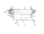
図1は本発明の実施の形態1に係る誘導加熱方式の加熱装置(像加熱装置)を概略で示す斜視図、図2は同加熱装置の軸直角断面図である。
【0029】
図1および図2に示す誘導加熱装置は、搬送される記録媒体である記録材14上に形成された未定着画像の現像剤を、熱によって融解して当該記録材14上に融着させるものであり、高周波磁界を生じるコイルユニット10と、コイルユニット10によって加熱され記録材14の搬送方向に沿って移動自在に設けられた加熱ローラ11(加熱媒体に相当する)と、加熱ローラ11と所定の距離をおいて固定されたホルダ12(絶縁部材に相当する)と、記録材14の搬送路を介してホルダ12および加熱ローラ11に対向してこれらに圧接する加圧ローラ13とを有する。加圧ローラ13は図2中矢印a方向に回転可能に設けられ、加熱ローラ11の回転に伴って従動回転する。
【0030】
未定着のトナー像が転写されている記録材14は、図中矢印bで示す方向から搬送され、記録材14を挟持するニップ部23に向けて送り込まれる。記録材14は、加熱された加熱ローラ11の熱と、加圧ローラ13から作用する圧力とが加えられながら、ニップ部23を搬送される。これにより、未定着トナーが定着され、記録材14上には定着トナー像が形成される。
【0031】
ニップ部23を通過した記録材14は、先端部が加熱ローラ11の表面に当接する分離爪15により加熱ローラ11から分離され、図2中左方向に搬送される。この記録材14は、排紙ローラ24によって搬送され、不図示の排紙トレイ上に排出される。
【0032】
前記加熱ローラ11は、薄肉の中空金属導体であり、例えばニッケル、鉄、SUS430などの導電性磁性材から形成される導電層を有している。そして加熱ローラ11の外周表面には、フッ素樹脂をコーティングして、耐熱性の離型層が形成されている。加熱ローラ11の金属層の厚さは、300μm〜1mmである。
【0033】
加熱ローラ11の内部には、当該加熱ローラ11に誘導電流(渦電流)を誘起させてジュール発熱させるために、高周波磁界を生じるコイルユニット10が配設されている。このコイルユニット10は、ホルダ12の内部に保持されている。ホルダ12は、図示しない定着ユニットフレームに固定され非回転となっている。
【0034】
コイルユニット10は、磁性材からなるコア16(芯材に相当する)と、加熱ローラ11に誘導電流を誘起させて加熱する誘導コイル18(誘導加熱源に相当する)とを有する。
【0035】
コア16としては、透磁率が大きく自己損失の小さい材料がよく、例えばフェライト、パーマロイ、センダスト等が適している。そして、コイルユニット10は前記ホルダ12内に、外部に露呈しないように収納されている。
【0036】
ホルダ12および分離爪15は、耐熱および電気絶縁性エンジニアリング・プラスチックから形成されている。
【0037】
加圧ローラ13は、軸芯19と、当該軸芯19の周囲に形成された表面離型性耐熱ゴム層であるシリコンゴム層20とから構成されている。
【0038】
加熱ローラ11の上方には、当該加熱ローラ11の温度を検出する温度センサ21が設けられている。この温度センサ21は、加熱ローラ11を隔てて誘導コイル18に向かい合うように、加熱ローラ11の表面に圧接している。温度センサ21は、例えば、サーミスタより構成され、このサーミスタで加熱ローラ11の温度を検出しつつ、加熱ローラ11の温度が最適温度となるように誘導コイル18への通電が制御される。
【0039】
次に本実施例を用いた加熱装置の動作、作用について述べる。
【0040】
誘導コイル18に高周波電流を通電すると、加熱ローラ11は磁性金属からなるので高周波誘導電流が誘起されて発熱する。しかも誘導加熱方式は発熱効率が高く、加熱ローラ11を薄肉に形成して低熱容量化をも図っているので、加熱ローラ11は高速で昇温する。
【0041】
この加熱ローラ11は、加圧ローラ13と圧接しながら、不図示の駆動源により駆動力を得て、該加圧ローラ13を伴って回転する。未定着のトナー像が転写されている記録材14は、これら加熱ローラ11と加圧ローラ13との間のニップ部23に向けて送り込まれ、加熱された加熱ローラ11の熱と加圧ローラ13から作用する圧力とが加えられながらニップ部23を搬送されることにより、トナーが記録材14上に定着される。
【0042】
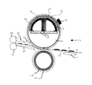
ここで、最大通紙幅よりも小形サイズの記録材を通紙する場合には、磁束遮蔽板31を図3に示すように、表面積を軸方向に変化させて配置する構成をとるとともに不図示のモータの駆動により、ホルダ12を回転可能にしたので、ホルダ12を回転することによって遮蔽部分の範囲を変化させることができ、限られたスペースの中で定着ローラ11の熱分布の制御が可能となっている。
【0043】
これにより、誘導コイル18から加熱ローラ11の非通紙領域へ届く磁束が遮蔽され、非通紙領域における加熱ローラ11の温度が通紙領域における加熱ローラ11の温調温度よりも上昇する事態が防止される。一方、大形サイズの記録材を通紙する場合には、モータ34の駆動により、磁束遮蔽板31は大形サイズの記録材の通紙幅の外側まで退避する。これにより、加熱ローラ11は誘導コイル18からの磁束を受けて均一に加熱される。
【0044】
このように磁束遮蔽板31を用いることにより、薄肉の加熱ローラ11であっても、通紙する記録材のサイズの種類によらず昇温される加熱ローラ11の熱分布をコントロールすることが可能となり、また必要部分以外は発熱自体をさせないので熱損失が小さく、省エネルギーともなる。
【0045】
したがって、加熱ローラ11の非通紙領域における温度上昇を低減させることが可能となり、該加熱ローラ11の長手方向の温度ムラを抑制することができる。これにより、小形サイズ記録材の通紙直後の大形サイズ記録材の通紙時における定着性の部分的なムラによる高温オフセットの発生、同じく小形サイズ記録材の通紙直後の大形サイズ記録材の通紙時における温度ムラによる紙シワ、スキューあるいはジャムの発生、加熱装置の構成部品の耐熱温度を越えることによる溶融、変形あるいは損傷などの加熱ローラ11の非通紙領域の温度上昇による不具合を効率良く防止することができる。
【0046】
本実施例では、加熱ローラ11と誘導コイル18との間に、ホルダ12の外面に沿うようにして、誘導コイル18から加熱ローラ11へ届く磁束の一部を遮蔽する磁束遮蔽板31(磁束遮蔽部材に相当する)が移動可能に設けられており、変位手段40により磁束遮蔽板31の位置を軸方向に変化させることによって、誘導電流による発熱範囲を制御することができる構成となっている。また、この発熱範囲の制御は、加熱ローラ11のように加熱媒体が薄肉で長手方向に熱移動が困難であるほど効果的なものとなる。
【0047】
磁束遮蔽板31としては、誘導電流を流す導電体であって固有抵抗の小さい非磁性材料である銅、アルミニウム、銀若しくはその合金等で体積抵抗値が5.0×10⁻⁸〔Ω・m〕以下である非磁性金属材料より形成されることが望ましい。
【0048】
磁束遮蔽板31は、図示のように、誘導コイル18の主として上半分を覆う円弧曲面を呈しており、小形サイズの記録材(図1中において二点銀線で示す)が通紙される場合には、加熱ローラ11の非通紙領域に相当する軸方向範囲の誘導コイル18を覆う位置(図1中において二点銀線で示す)まで、変位手段40により移動される。一方、大形サイズの記録材が通紙される場合には、大形サイズの記録材の通紙幅の外側まで磁束遮蔽板31を退避させるようになっている。
【0049】
このように、磁束遮蔽板31は、加熱ローラ11における通紙範囲に応じて変位手段40によりその位置が変化させられるため、種々の幅の記録材に対応可能となる。この通紙範囲は、記録材の給紙部のサイズ検出手段により情報を得る構成とされるが、あるいは、加熱ローラ11や加圧ローラ13等の温度を検出する手段を軸方向に沿って複数設けることにより検出する構成としてもよい(いずれも図示せず)。なお、磁束遮蔽板31は円弧曲面のものに限られず、円筒形状とすることも可能である。
【0050】
磁束遮蔽板31を図4に磁束遮蔽板31の厚みと立ち上がり速度の関係、及び図5に加熱装置加熱時の磁束遮蔽板の温度及び磁気遮蔽部分に対応する誘導コイル18の温度を示す。
【0051】
実験条件:定着ローラφ40 Fe芯金 0.5mm厚 ニップ幅 7mm
800W入力 180℃温調 A4R80g紙 40cpm通紙
300mm/sec 遮蔽板材質:Al 誘導コイル:ポリアミドイミド
図4に示すように、室温(25℃)から例えば定着が可能である定着ローラ温度(160℃)まで立ち上げるのに約30秒で立ち上げるためには、
(160−25)/30=4.5[℃/sec]
の昇温速度が最低限必要である。このためには遮蔽板31の厚みは2mm以下であることが必要となる。
【0052】
また、図5に示すように、遮蔽板31が薄くなると遮蔽板31自体に自己発熱が起き、その近傍にあるコイル18の温度を上昇させることになる。コイル被覆の耐熱温度が220℃であることから、遮蔽板31の厚みは最低0.1mmは必要となる。以上より磁束遮蔽板31の厚みを0.1mm〜2mmに設定することが適当であると考えられる。
【0053】
なお、以上説明した実施形態は、本発明を限定するために記載されたものではなく、種々変更が可能である。例えば上述した実施の形態では、加熱媒体として中空の金属ローラを使用した誘導加熱装置について説明したが、本発明はこれに限られるものではなく、可撓性を有する加熱ローラを使用した誘導加熱装置に対しても勿論適用することができる。
【0054】
[実施の形態2]
以下図面に従い説明するが、実施の形態1と同じ部材は同じ番号を付し、説明は省略する。
【0055】
図6は本発明の実施の形態2に係る誘導加熱方式の加熱装置を概略で示す横断面図、図7は同加熱装置に用いた磁束遮蔽板の斜視図である。磁束遮蔽板32はベース層34を金属表層33で挟み込んだ構成をとっている。本実施例では金属表層33は銀でできており10μmの厚みを持っている。また、ベース層34はアルミよりなっており、200μmの厚みを有している。
【0056】
磁束遮蔽板32はベース層であるアルミ板に銀をめっきして作成される。金属表層33は薄いため自己発熱をするが、それでも銀という抵抗の低い材料で形成されているため、発熱度合いは少ない。
【0057】
また、熱が発生したとしても、アルミに伝播されるため、局所的な発熱は起こらない。さらに銀のみでこの厚みの部材を形成すると、自己発熱は抑えられるが、コストが割高となる。この構成は比較的安価で自己発熱をしない磁束遮蔽板を提供することができる。この場合、表層にはアルミ、銀、銅などの低抵抗物質を、またベース層には非磁性の金属であるアルミ、銅、SUS304等を使用することができる。
【0058】
また、金属表層33にアルミ0.1mmを用いた構成では金属表層での自己発熱がないため、磁束遮蔽板32は加熱媒体である定着ローラ11の熱を奪わないことが求められる。このため、ベース層34をポリイミド、液晶ポリマー、ポリアミドイミド等熱伝導性の低い耐熱樹脂や炭化ケイ素、窒化ケイ素、アルミナ等のセラミックを用いることで、熱効率を向上させることができる。
【0059】
【発明の効果】
以上述べたように、本発明によれば、加熱媒体がたとえ薄肉であっても、通紙する記録材のサイズの種類によらず昇温される加熱媒体の熱分布をコントロールすることを可能とする磁束遮蔽部材の厚みを限定したため、磁気遮蔽部材の発熱を抑えるようにし、熱容量を小さくしたため、立ち上げ時間が短縮されるとともに熱損失が小さく、省エネルギーともなる。
【0061】
したがって、加熱媒体の非通紙領域における温度上昇を低減させることが可能となり、該加熱媒体の長手方向の温度ムラを抑制することができる。これにより、小形サイズ記録材の通紙直後の大形サイズ記録材の通紙時における定着性の部分的なムラによる高温オフセットの発生、同じく小形サイズ記録材の通紙直後の大形サイズ記録材の通紙時における温度ムラによる紙シワ、スキューあるいはジャムの発生、加熱媒体における温度分布差による内部熱応力の発生およびこれに伴う劣化、像加熱装置の構成部品の耐熱温度を越えることによる溶融、変形あるいは損傷などの加熱媒体の非通紙領域の温度上昇による不具合を、効率良く防止することができる。
【図面の簡単な説明】
【図1】 実施の形態1に係る誘導加熱方式の加熱装置を概略で示す斜視図である。
【図2】 同加熱装置の軸直角断面図である。
【図3】 実施の形態1に係る誘導加熱方式の加熱装置の磁束遮蔽板を概略で示す斜視図である。
【図4】 実施の形態1に係る誘導加熱方式の加熱装置における磁束遮蔽板の厚みと加熱装置の立ち上げ速度の関係を示すグラフである。
【図5】 実施の形態1に係る誘導加熱方式の加熱装置における磁束遮蔽板の厚みと遮蔽板温度及びコイル温度の関係を示すグラフである。
【図6】 実施の形態2に係る誘導加熱方式の加熱装置の軸直角断面図である。
【図7】 実施の形態2に係る誘導加熱方式の加熱装置の磁束遮蔽板を概略で示す斜視図である。
【符号の説明】
11 加熱ローラ(加熱媒体)
12 ホルダ(絶縁部材)
13 加圧ローラ
14 記録材
16 コア(芯材)
18 誘導コイル(誘導加熱源)
31、32 磁束遮蔽部材
33 金属表層
34 ベース層[0001]
BACKGROUND OF THE INVENTION
The present invention is an electrophotographic copying machine, a printer, a facsimile, or an image heating apparatus which is mounted in an image forming apparatus such as a complex machine thereof, and an image forming apparatus Ru with the image heating apparatus.
[0002]
[Prior art]
In an electrophotographic copying machine, the toner (developer) of a toner image (unfixed image) transferred onto a recording material that is a recording medium to be conveyed is melted by heat and melted on the recording material. A heating device is provided.
[0003]
In this heating device, in order to increase the temperature at high speed, a fixing roller, which is a heating medium, has a small diameter, a resin film rotating body is pressed against the rotating body from inside, and a thin metal rotating body is induced. Although the thing etc. which heat by heating are known, all are trying to make the heat capacity of the rotary body which is a heating medium small, and to heat with a heat source with good heating efficiency.
[0004]
In addition, some non-contact heating sources are used, but from the viewpoint of cost and energy efficiency, in image forming apparatuses such as copying machines, a thin rotating body is brought into contact with the recording material, and the developer on the recording material is removed. Many types of heating devices that heat and melt have been proposed.
[0005]
However, when a thin rotating body is used as a heating medium in order to reduce the heat capacity, the cross-sectional area of the cross section perpendicular to the axis is extremely small, so that the heat transfer rate in the axial direction is not good. This tendency becomes more conspicuous as the wall becomes thinner, and is even lower for materials such as resins with low thermal conductivity.
[0006]
This means that when the thermal conductivity is λ, the temperature difference between two points is θ1-θ2, and the length is L, the amount of heat Q transmitted per unit time is
Q = λ · f (θ1-θ2) / L
It is clear from the Fourier law expressed by
[0007]
This is not a problem when the recording material full of the length in the longitudinal direction of the rotating body, that is, the recording material having the maximum sheet passing width is fixed and passed, but a small-sized recording material having a small width is continuously passed. When paper is used, there is a problem that the temperature in the non-sheet passing area of the rotating body rises higher than the temperature control temperature, and the temperature difference between the temperature in the sheet passing area and the temperature in the non-sheet passing area becomes extremely large. It was.
[0008]
Therefore, due to the temperature unevenness in the longitudinal direction of the heating medium, there is a possibility that the heat-resistant life of the peripheral member made of the resin material may be reduced or thermally damaged. There is also a problem that when a large-sized recording material is passed immediately after the material is continuously fed, paper wrinkles, skew, etc. due to partial temperature unevenness and fixing unevenness may occur.
[0009]
Such a temperature difference between the sheet passing area and the non-sheet passing area increases as the heat capacity of the recording material to be conveyed increases and the throughput (number of printed sheets per unit time) increases. For this reason, in the case where the heating device is constituted by a thin-walled rotating body having a low heat capacity, it has been difficult to apply it to a copying machine with high throughput.
[0010]
On the other hand, in a heating apparatus using a halogen lamp or a heating resistor as a heating source, there is known a device that divides the heating source and selectively energizes so as to heat a region corresponding to the sheet passing width.
[0011]
Some heating apparatuses using an induction coil as a heating source similarly divide the heating source and selectively energize it.
[0012]
However, if a plurality of heating sources are provided or divided, the control circuit becomes more complicated and more expensive, and the number of divisions is further increased and the cost is further increased when trying to cope with recording materials of various widths. It will be a thing. Moreover, when a thin rotating body is used as a heating medium, the temperature distribution near the boundary when divided is discontinuous and non-uniform, which may affect the fixing performance.
[0013]
Therefore, a magnetic flux shielding means for shielding a part of the magnetic flux reaching the heating medium from the induction heating source is arranged between the heating medium and the induction heating source, and a displacement means for changing the position of the magnetic flux shielding means is provided. Has been proposed until. (JP-A-9-17889, JP-A-10-74009) In this invention, by providing and moving the magnetic flux shielding means, the magnetic flux reaching from the induction heating source is shielded except for the necessary part, and the heat generation itself is generated. By being suppressed, the heat generation range is controlled, and the heat distribution of the heating medium to be heated can be controlled.
[0014]
As a magnetic flux shielding plate, in order to prevent the temperature rise of the magnetic flux shielding plate itself, copper, aluminum, silver or an alloy thereof, or a magnetic flux is confined as a non-magnetic material having a small specific resistance, which is a conductor through which an induced current flows. Ferrite with a large specific resistance is suitable, and even magnetic materials such as iron and nickel can be used by forming holes such as yen bills and slits to suppress heat generation due to eddy currents. Yes.
[0015]
[Problems to be solved by the invention]
However, since the magnetic flux shielding plate in the conventional example is disposed in the vicinity of the heating medium, it has the following drawbacks.
[0016]
1) When the magnetic flux shielding plate is formed of copper, silver, aluminum, etc. having high conductivity, these metal materials are generally good thermal conductivity. Therefore, when the heat capacity is increased, the heat transfer from the heating medium is prevented. It increases and the heating rate of the heating medium is slowed down. In addition, if an extremely thin material is used to reduce the heat capacity, the magnetic flux is not completely shielded, and the magnetic flux shielding plate self-heats due to the concentration of the magnetic flux. Insulating properties of the insulating layer covering the coil forming the coil are impaired.
[0017]
2) When using a magnetic flux shielding plate in the vicinity of a cylindrical heating medium, it is necessary to make the magnetic flux shielding plate in an arc shape. However, magnetic materials such as ferrite having a large specific resistance are generally poor in formability and have an arc shape. It is difficult to mold.
[0018]
3) When the magnetic flux shielding plate is made of a magnetic material such as iron or nickel and provided with a circular hole or slit to suppress self-heating, the magnetic flux leaks to the heating member even slightly, and heat is generated in the non-paper passing area. Therefore, energy is wasted.
[0019]
The present invention is Ru der been made to solve the problems associated with the prior art. An object of the present invention without compromising the rise time, the temperature rise is suppressed in the non-paper passing area of the heating medium and an image forming apparatus including an image heating device and an image heating apparatus can also be prevented abnormal Atsushi Nobori of the coil Is to provide.
[0020]
[Means for Solving the Problems]
(1) A heating medium having a coil and a conductive layer that generates heat due to a magnetic flux generated when a current flows through the coil, the heating medium for heating an image on a recording material, and a magnetic flux having at least one conductive layer. A magnetic flux shielding member that shields a part of the magnetic flux reaching the heating medium from the coil, and the magnetic flux shielding member has a magnetic flux shielding position inside the heating medium between the heating medium and the coil. In the image heating apparatus that moves between the retracted position inside the heating medium that retracts from the position,
The thickness of the conductive layer of the heating medium is at 300μm to 1mm, an image heating apparatus, wherein the thickness of the magnetic flux shielding member is 0. 1mm or 2mm or less.
[0022]
(2) The image heating apparatus according to (1), wherein the heating medium has a release layer on the conductive layer, and the conductive layer of the heating medium faces the magnetic flux shielding member.
[0023]
(3) The image heating apparatus according to (1) or (2), wherein the magnetic flux shielding member includes a layer having a thermal conductivity different from that of the conductive layer.
[0024]
(4) The image heating apparatus according to any one of (1) to (3), wherein the magnetic flux shielding member has a resin layer.
[0025]
(5) The image heating apparatus according to any one of (1) to (4), wherein the conductive layer has a volume resistivity of 5.0 × 10 −8 Ω · m or less.
[0026]
(6) An image forming apparatus for forming an image on a recording material, the image heating device according to any one of (1) to (5) being provided as an image heating device for heating the image on the recording material. An image forming apparatus.
[0027]
DETAILED DESCRIPTION OF THE INVENTION
[Embodiment 1]
Hereinafter, embodiments of the present invention will be described with reference to the drawings.
[0028]
1 is a perspective view schematically showing a heating apparatus (image heating apparatus) of an induction heating system according to
[0029]
The induction heating apparatus shown in FIGS. 1 and 2 melts a developer of an unfixed image formed on a
[0030]
The
[0031]
The
[0032]
The
[0033]
A
[0034]
The
[0035]
The
[0036]
The
[0037]
The
[0038]
A
[0039]
Next, the operation and action of the heating apparatus using this embodiment will be described.
[0040]
When the
[0041]
The
[0042]
Here, when a recording material having a size smaller than the maximum sheet passing width is passed, the magnetic
[0043]
As a result, the magnetic flux reaching the non-sheet passing area of the
[0044]
By using the magnetic
[0045]
Therefore, it is possible to reduce the temperature rise in the non-sheet passing region of the
[0046]
In this embodiment, a magnetic flux shielding plate 31 (magnetic flux shielding) that shields part of the magnetic flux reaching the
[0047]
The magnetic
[0048]
As shown in the figure, the magnetic
[0049]
Thus, since the position of the magnetic
[0050]
FIG. 4 shows the relationship between the thickness of the magnetic
[0051]
Experimental conditions: fixing roller φ40 Fe cored bar 0.5 mm
800 W input 180 ° C temperature control A4R80g paper 40 cpm paper passing 300 mm / sec Shield plate material: Al Inductive coil: Polyamideimide As shown in FIG. 4, for example, fixing roller temperature (160 ° C) at which fixing can be performed from room temperature (25 ° C) To start up in about 30 seconds,
(160-25) /30=4.5 [° C./sec]
Is required at a minimum. For this purpose, the thickness of the shielding
[0052]
Further, as shown in FIG. 5, when the shielding
[0053]
The embodiment described above is not described to limit the present invention, and various modifications can be made. For example, in the above-described embodiment, the induction heating apparatus using a hollow metal roller as the heating medium has been described. However, the present invention is not limited to this, and the induction heating apparatus using a flexible heating roller is used. Of course, it can be applied to.
[0054]
[Embodiment 2]
The following description will be made with reference to the drawings, but the same members as those in the first embodiment are denoted by the same reference numerals and description thereof will be omitted.
[0055]
FIG. 6 is a transverse cross-sectional view schematically showing an induction heating type heating apparatus according to
[0056]
The magnetic
[0057]
Moreover, even if heat is generated, it is propagated to aluminum, so local heat generation does not occur. Further, when a member having this thickness is formed only of silver, self-heating is suppressed, but the cost is high. This configuration can provide a magnetic flux shielding plate that is relatively inexpensive and does not generate heat. In this case, a low resistance material such as aluminum, silver, or copper can be used for the surface layer, and aluminum, copper, SUS304, or the like, which is a nonmagnetic metal, can be used for the base layer.
[0058]
Further, in the configuration in which aluminum 0.1 mm is used for the
[0059]
【The invention's effect】
As described above, according to the present invention, even if the heating medium is thin, it is possible to control the heat distribution of the heating medium that is heated regardless of the size of the recording material to be passed. Since the thickness of the magnetic flux shielding member is limited, the heat generation of the magnetic shielding member is suppressed and the heat capacity is reduced, so that the start-up time is shortened, the heat loss is small, and the energy is saved.
[0061]
Therefore, it is possible to reduce the temperature rise in the non-sheet passing region of the heating medium, and to suppress temperature unevenness in the longitudinal direction of the heating medium. As a result, high-temperature offset occurs due to partial unevenness in fixability when a large size recording material is passed immediately after the small size recording material is passed, and the large size recording material is also immediately after the small size recording material is passed. Generation of paper wrinkles, skew or jam due to temperature unevenness when passing through, generation of internal thermal stress due to temperature distribution difference in the heating medium and deterioration due to this, melting due to exceeding the heat resistance temperature of the components of the image heating device, Problems due to temperature rise in the non-sheet passing region of the heating medium such as deformation or damage can be efficiently prevented.
[Brief description of the drawings]
[1] The heating apparatus of the induction heating type according to
FIG. 2 is a cross-sectional view perpendicular to the axis of the heating device.
[3] The magnetic flux shielding plate of the heating apparatus of the induction heating type according to
4 is a graph showing the rise rate relationship of the heating device and the thickness of the magnetic flux shielding plate in the heating apparatus of the induction heating type according to
5 is a graph showing the thickness and the shielding plate temperature and the relationship of the coil temperature of the magnetic flux shielding plate in the heating apparatus of the induction heating type according to
6 is an axial sectional view perpendicular to the heating apparatus of the induction heating method according to a second implementation.
7 is a perspective view showing a magnetic flux shielding plate in schematic of the heating apparatus of the induction heating method according to a second implementation.
[Explanation of symbols]
11 Heating roller (heating medium)
12 Holder (insulating member)
13
18 Induction coil (Induction heating source)
31, 32 Magnetic
Claims (6)
加熱媒体の前記導電層の厚みは300μm以上1mm以下であり、前記磁束遮蔽部材の厚みは0.1mm以上2mm以下であることを特徴とする像加熱装置。A heating medium having a coil and a conductive layer that generates heat due to a magnetic flux generated when a current flows through the coil, the heating medium for heating an image on a recording material, and a magnetic flux shielding member having at least one conductive layer A magnetic flux shielding member that shields a part of the magnetic flux reaching the heating medium from the coil, and the magnetic flux shielding member is located between the heating medium and the coil from the magnetic flux shielding position inside the heating medium and the position thereof. In the image heating apparatus that moves between the retreat positions inside the retreat heating medium ,
The thickness of the said conductive layer of a heating medium is 300 micrometers or more and 1 mm or less, The thickness of the said magnetic flux shielding member is 0.1 mm or more and 2 mm or less, The image heating apparatus characterized by the above-mentioned .
Priority Applications (2)
| Application Number | Priority Date | Filing Date | Title |
|---|---|---|---|
| JP2001158641A JP3880334B2 (en) | 2001-05-28 | 2001-05-28 | Image heating apparatus and image forming apparatus |
| US10/155,182 US6687481B2 (en) | 2001-05-28 | 2002-05-28 | Inductive thermal fixing apparatus having magnetic flux blocking plate with specific thickness |
Applications Claiming Priority (1)
| Application Number | Priority Date | Filing Date | Title |
|---|---|---|---|
| JP2001158641A JP3880334B2 (en) | 2001-05-28 | 2001-05-28 | Image heating apparatus and image forming apparatus |
Publications (3)
| Publication Number | Publication Date |
|---|---|
| JP2002352948A JP2002352948A (en) | 2002-12-06 |
| JP2002352948A5 JP2002352948A5 (en) | 2004-10-28 |
| JP3880334B2 true JP3880334B2 (en) | 2007-02-14 |
Family
ID=19002327
Family Applications (1)
| Application Number | Title | Priority Date | Filing Date |
|---|---|---|---|
| JP2001158641A Expired - Lifetime JP3880334B2 (en) | 2001-05-28 | 2001-05-28 | Image heating apparatus and image forming apparatus |
Country Status (2)
| Country | Link |
|---|---|
| US (1) | US6687481B2 (en) |
| JP (1) | JP3880334B2 (en) |
Families Citing this family (28)
| Publication number | Priority date | Publication date | Assignee | Title |
|---|---|---|---|---|
| KR100531541B1 (en) * | 2001-11-01 | 2005-11-29 | 마쯔시다덴기산교 가부시키가이샤 | Electromagnetic induced heating roller, heating apparatus, and image forming apparatus |
| US7194234B2 (en) * | 2001-11-01 | 2007-03-20 | Matsushita Electric Industrial Co., Ltd. | Electromagnetic induction heat generating roller, heating device, and image forming apparatus |
| KR100557910B1 (en) * | 2001-11-01 | 2006-03-10 | 마쯔시다덴기산교 가부시키가이샤 | Heating roller, image heating apparatus, and image forming apparatus |
| KR100574805B1 (en) * | 2001-11-14 | 2006-04-27 | 마쯔시다덴기산교 가부시키가이샤 | Heating roller, heating belt, image heating device, and image forming device |
| US7009158B2 (en) * | 2003-02-28 | 2006-03-07 | Canon Kabushiki Kaisha | Image forming apparatus |
| JP4110047B2 (en) * | 2003-06-10 | 2008-07-02 | キヤノン株式会社 | Image heating device |
| JP2005121899A (en) * | 2003-10-16 | 2005-05-12 | Sharp Corp | Fixing device and image forming apparatus |
| US7369804B2 (en) * | 2003-10-17 | 2008-05-06 | Matsushita Electric Industrial Co., Ltd. | Fixing device |
| JP4353419B2 (en) | 2004-02-12 | 2009-10-28 | 株式会社リコー | Fixing apparatus and image forming apparatus |
| US20050205559A1 (en) * | 2004-03-22 | 2005-09-22 | Kabushiki Kaisha Toshiba | Image forming apparatus |
| JP4241476B2 (en) * | 2004-04-01 | 2009-03-18 | キヤノン株式会社 | Image heating apparatus and image forming apparatus |
| US7925177B2 (en) | 2004-07-21 | 2011-04-12 | Ricoh Co, Ltd. | Image fixing apparatus stably controlling a fixing temperature, and image forming apparatus using the same |
| JP4526019B2 (en) * | 2004-07-21 | 2010-08-18 | 株式会社リコー | Fixing apparatus and image forming apparatus |
| KR100767487B1 (en) * | 2004-10-22 | 2007-10-17 | 캐논 가부시끼가이샤 | Image forming apparatus |
| JP4717412B2 (en) * | 2004-10-22 | 2011-07-06 | キヤノン株式会社 | Heating device |
| JP4652769B2 (en) * | 2004-10-22 | 2011-03-16 | キヤノン株式会社 | Induction heating fixing device |
| JP4208816B2 (en) * | 2004-10-22 | 2009-01-14 | キヤノン株式会社 | Image heating device |
| JP4721331B2 (en) * | 2004-12-16 | 2011-07-13 | 株式会社リコー | Fixing apparatus and image forming apparatus |
| JP2006251025A (en) * | 2005-03-08 | 2006-09-21 | Canon Inc | Heating apparatus |
| US7205513B2 (en) * | 2005-06-27 | 2007-04-17 | Xerox Corporation | Induction heated fuser and fixing members |
| JP4281779B2 (en) | 2006-10-20 | 2009-06-17 | コニカミノルタビジネステクノロジーズ株式会社 | Fixing apparatus and image forming apparatus |
| US8078072B2 (en) * | 2008-01-07 | 2011-12-13 | Kyocera Mita Corporation | Image forming apparatus with image fixing device including an induction heater and a shield located between two sections of a core of the induction heater |
| JP5175657B2 (en) * | 2008-08-25 | 2013-04-03 | 京セラドキュメントソリューションズ株式会社 | Image forming apparatus |
| JP5386218B2 (en) * | 2009-04-24 | 2014-01-15 | 京セラドキュメントソリューションズ株式会社 | Fixing apparatus and image forming apparatus equipped with the same |
| JP5503248B2 (en) * | 2009-10-19 | 2014-05-28 | キヤノン株式会社 | Image heating device |
| JP6069828B2 (en) * | 2011-12-05 | 2017-02-01 | 株式会社リコー | Fixing apparatus and image forming apparatus |
| US20150043162A1 (en) * | 2013-08-12 | 2015-02-12 | Wah Hong Industrial Corp. | Central processing unit casing |
| JP6335651B2 (en) | 2014-05-26 | 2018-05-30 | キヤノン株式会社 | Heater and image heating apparatus provided with the same |
Family Cites Families (14)
| Publication number | Priority date | Publication date | Assignee | Title |
|---|---|---|---|---|
| JP3624040B2 (en) | 1995-12-20 | 2005-02-23 | キヤノン株式会社 | Heating device |
| JPH1074009A (en) | 1996-08-30 | 1998-03-17 | Minolta Co Ltd | Fixing device |
| US6055403A (en) | 1998-01-28 | 2000-04-25 | Canon Kabushiki Kasiha | Fixing member fixing apparatus and electrophotographic apparatus using them |
| JPH11352804A (en) * | 1998-06-04 | 1999-12-24 | Fuji Xerox Co Ltd | Image recorder |
| JP2000012204A (en) | 1998-06-25 | 2000-01-14 | Canon Inc | Heating device and image forming device |
| JP2000356919A (en) | 1999-04-15 | 2000-12-26 | Canon Inc | Image heating device and coil for heating image |
| US6414500B1 (en) * | 1999-05-14 | 2002-07-02 | Mitsubishi Denki Kabushiki Kaisha | Test socket for an electronic circuit device having improved contact pins and manufacturing method thereof |
| JP2001005315A (en) * | 1999-06-17 | 2001-01-12 | Matsushita Electric Ind Co Ltd | Image heating device and heat roller used therefor and image forming device |
| JP2001194943A (en) | 1999-11-05 | 2001-07-19 | Canon Inc | Fixing roller and fixing device |
| WO2001048559A1 (en) * | 1999-12-28 | 2001-07-05 | Toshiba Tec Kabushiki Kaisha | Image forming apparatus and photographic fixing device |
| JP3550582B2 (en) * | 1999-12-28 | 2004-08-04 | 東芝テック株式会社 | Fixing device |
| JP2002083676A (en) * | 2000-09-08 | 2002-03-22 | Canon Inc | Heating apparatus and image forming apparatus |
| JP2002110336A (en) * | 2000-09-27 | 2002-04-12 | Fuji Xerox Co Ltd | Electromagnetic induction heating device and image recording device using the same |
| US6721530B2 (en) * | 2001-03-28 | 2004-04-13 | Hewlett-Packard Development Company, L.P. | Fusing system having electromagnetic heating |
-
2001
- 2001-05-28 JP JP2001158641A patent/JP3880334B2/en not_active Expired - Lifetime
-
2002
- 2002-05-28 US US10/155,182 patent/US6687481B2/en not_active Expired - Lifetime
Also Published As
| Publication number | Publication date |
|---|---|
| JP2002352948A (en) | 2002-12-06 |
| US6687481B2 (en) | 2004-02-03 |
| US20020186991A1 (en) | 2002-12-12 |
Similar Documents
| Publication | Publication Date | Title |
|---|---|---|
| JP3880334B2 (en) | Image heating apparatus and image forming apparatus | |
| JP4717412B2 (en) | Heating device | |
| JP5673053B2 (en) | Fixing apparatus and image forming apparatus | |
| JPH1074009A (en) | Fixing device | |
| JP5371943B2 (en) | Image heating device | |
| JP5503248B2 (en) | Image heating device | |
| JP4738872B2 (en) | Image heating device | |
| JP2013037056A (en) | Image heating device | |
| JP2002083676A (en) | Heating apparatus and image forming apparatus | |
| JP2013037052A (en) | Image heating device | |
| JP5743577B2 (en) | Image heating device | |
| JP5487177B2 (en) | Fixing apparatus and image forming apparatus | |
| JP2002190377A (en) | Heating device, image-heating device, and imaging device | |
| JP2003077645A (en) | Heater and image forming device | |
| JP2002014566A (en) | Fixing device | |
| JP4526019B2 (en) | Fixing apparatus and image forming apparatus | |
| JP2001318546A (en) | Fixing device | |
| JP5699676B2 (en) | Fixing apparatus and image forming apparatus | |
| JP2002343548A (en) | Heating device and image forming device | |
| JPH09127811A (en) | Fixing device | |
| JP5372287B2 (en) | Image heating device | |
| JP2005221921A (en) | Fixing device and image forming apparatus | |
| JP5693687B2 (en) | Image heating device | |
| JP2005056598A (en) | Heating device and image forming device | |
| JP5210958B2 (en) | Fixing apparatus and image forming apparatus equipped with the same |
Legal Events
| Date | Code | Title | Description |
|---|---|---|---|
| A131 | Notification of reasons for refusal |
Free format text: JAPANESE INTERMEDIATE CODE: A131 Effective date: 20060425 |
|
| A521 | Written amendment |
Free format text: JAPANESE INTERMEDIATE CODE: A523 Effective date: 20060626 |
|
| TRDD | Decision of grant or rejection written | ||
| A01 | Written decision to grant a patent or to grant a registration (utility model) |
Free format text: JAPANESE INTERMEDIATE CODE: A01 Effective date: 20061024 |
|
| A61 | First payment of annual fees (during grant procedure) |
Free format text: JAPANESE INTERMEDIATE CODE: A61 Effective date: 20061107 |
|
| R150 | Certificate of patent or registration of utility model |
Free format text: JAPANESE INTERMEDIATE CODE: R150 Ref document number: 3880334 Country of ref document: JP Free format text: JAPANESE INTERMEDIATE CODE: R150 |
|
| FPAY | Renewal fee payment (event date is renewal date of database) |
Free format text: PAYMENT UNTIL: 20101117 Year of fee payment: 4 |
|
| FPAY | Renewal fee payment (event date is renewal date of database) |
Free format text: PAYMENT UNTIL: 20101117 Year of fee payment: 4 |
|
| FPAY | Renewal fee payment (event date is renewal date of database) |
Free format text: PAYMENT UNTIL: 20111117 Year of fee payment: 5 |
|
| FPAY | Renewal fee payment (event date is renewal date of database) |
Free format text: PAYMENT UNTIL: 20121117 Year of fee payment: 6 |
|
| FPAY | Renewal fee payment (event date is renewal date of database) |
Free format text: PAYMENT UNTIL: 20131117 Year of fee payment: 7 |
|
| RD03 | Notification of appointment of power of attorney |
Free format text: JAPANESE INTERMEDIATE CODE: R3D03 |
|
| EXPY | Cancellation because of completion of term |