JP2005292531A - Light quantity adjusting device and projector using the same - Google Patents
Light quantity adjusting device and projector using the same Download PDFInfo
- Publication number
- JP2005292531A JP2005292531A JP2004108719A JP2004108719A JP2005292531A JP 2005292531 A JP2005292531 A JP 2005292531A JP 2004108719 A JP2004108719 A JP 2004108719A JP 2004108719 A JP2004108719 A JP 2004108719A JP 2005292531 A JP2005292531 A JP 2005292531A
- Authority
- JP
- Japan
- Prior art keywords
- light
- optical path
- light amount
- amount adjusting
- light quantity
- Prior art date
- Legal status (The legal status is an assumption and is not a legal conclusion. Google has not performed a legal analysis and makes no representation as to the accuracy of the status listed.)
- Pending
Links
Images


Landscapes
- Diaphragms For Cameras (AREA)
- Projection Apparatus (AREA)
Abstract
Description
本発明は液晶パネルなどの画像形成手段で形成した画像を投影レンズでスクリーン上に投影する際の光量を調節する光量調節装置及びこれを用いたプロジェクタ装置に関する。 The present invention relates to a light amount adjusting device for adjusting a light amount when an image formed by image forming means such as a liquid crystal panel is projected on a screen by a projection lens, and a projector device using the same.
一般に液晶プロジェクタなどの光映像をスクリーン上に投影する装置は、コンピュータ、テレビなどの画像機器に接続され、これ等の画像機器から出力された映像を投射レンズでスクリーン上に投影するものとして広く使用されている。 In general, a device that projects an optical image such as a liquid crystal projector on a screen is connected to an image device such as a computer or a television, and is widely used as an image projected from the image device on a screen using a projection lens. Has been.
このようなプロジェクタ装置で投影した光画像は使用する環境によって眩しく感じたり、暗く感ずることがある。その原因は例えば暗い場所で使用する人間の瞳孔が開いている状態で急に明るい映像にすると光を実際より強く感ずる為であり、逆に明るい場所ではスクリーンの画面を暗く感ずる等周囲の明るさによる見易さが問題となる。 An optical image projected by such a projector device may feel dazzling or dark depending on the environment in which it is used. The reason for this is, for example, that when the human pupil used in a dark place is open and suddenly a bright image is made, the light feels stronger than it actually is. On the other hand, in a bright place, the screen screen appears darker. Ease of viewing is a problem.
そこでスクリーンに投影する画像の明るさを周囲の環境に応じて調節する必要が生ずる。従来このような投影光量を調節する方法としては、液晶パネル等に照射する光源を調節するか、液晶パネルに印加する電圧を調節する方法が例えば特許文献1(特開2000−28988号公報)に知られている。 Therefore, it is necessary to adjust the brightness of the image projected on the screen according to the surrounding environment. Conventionally, as a method for adjusting the amount of projection light, for example, Patent Document 1 (Japanese Patent Laid-Open No. 2000-28988) discloses a method of adjusting a light source applied to a liquid crystal panel or the like or adjusting a voltage applied to the liquid crystal panel. Are known.
従来このような投影光量(スクリーン画像の明るさ)を調節する方法としては液晶パネルに印加する電圧を調節することが知られている。しかし液晶パネルは電圧と透過率との間に特有の関係があり、電圧を変えることで明るさを変える際に赤青緑が均等に変化するように電圧をコントロールするのは難しく、また、明るさの調節の際に色あいも変わってしまうという問題があった。 Conventionally, as a method of adjusting the projection light quantity (brightness of the screen image), it is known to adjust the voltage applied to the liquid crystal panel. However, liquid crystal panels have a unique relationship between voltage and transmittance, and it is difficult to control the voltage so that red, blue and green change evenly when changing the brightness by changing the voltage. There was a problem that the hue changed when adjusting the thickness.
そこで投影レンズで投射する光量を遮光マスク板で調節してスクリーン画像の明るさを一定に調節することが例えば特許文献2(特開2003−121938号公報)などで提案されている。同文献には投射レンズの前面にレンズの投影光路と直交する方向に投影孔(レンズ孔)を有するベース部材を設け、このベース部材に投影孔の口径を大小に調節する遮光板(マスク部材)を光路と直交する方向に開閉自在に取付けて光量調節するものが開示されている。従って液晶パネルに形成された画像は光源からの光を受けて投射レンズでスクリーンに照射される際の画隔を投影光路に対して直交する平面に設けられた遮光板で光路の開口を大小に調節することによってスクリーン上の画像の明るさを調節するようにしている。
上述のように投射レンズで投影する光路の光量を遮光板(マスク部材)で調節する際に前掲特許文献2のように投影光路と直交する平面でこの平面に設けた遮光板をスライド移動させて光量調節しようとすると投影レンズの側部に遮光部材(羽根状のマスク板など)が進退するスペースとこの遮光部材を開閉する駆動機構の配置スペースが必要となる。 As described above, when the light amount of the optical path projected by the projection lens is adjusted by the light shielding plate (mask member), the light shielding plate provided on this plane is slid on the plane orthogonal to the projection optical path as in Patent Document 2 described above. In order to adjust the amount of light, a space where a light shielding member (such as a blade-like mask plate) advances and retreats on the side of the projection lens and a space for arranging a driving mechanism for opening and closing the light shielding member are required.
一方投影レンズは通常円形状であり筒形状の鏡筒部に組込まれる為レンズの側方に光量調節装置が突出することとなる。従って装置の小型化、省スペース化に好ましくない結果をもたらしていた。かかる問題を解決する為本発明は投影レンズでスクリーン上に投影する光路の左右に一対の遮光板(羽根部材)を設け、この遮光板を光路の進行方向に揺動させて光路の開口量を調節することによって遮光板を光路と直交する平面内で進退自在に構成する場合に比べ装置の省スペース化と小型化を図るとの知見に基づいてなされたものである。 On the other hand, since the projection lens is usually circular and is incorporated in a cylindrical lens barrel, the light amount adjusting device protrudes to the side of the lens. Therefore, it has resulted in undesirable results in downsizing and space saving of the apparatus. In order to solve this problem, the present invention provides a pair of light shielding plates (blade members) on the left and right sides of the optical path projected onto the screen by the projection lens, and swings the light shielding plates in the traveling direction of the optical path to reduce the opening amount of the optical path. This is based on the knowledge that, by adjusting, the light-shielding plate can be moved forward and backward in a plane orthogonal to the optical path, the apparatus can be reduced in space and size.
ところがこのような構成の採用により新たに次の問題が生ずる。つまり図11に示すように投影光路内にこの光路の進行方向に回動(揺動)自在の一対の羽根部材は開閉機構のガタつきによって正確な光量のコントロールが難しく、特に光路の開口を大きく開いた状態での光量調節が困難となる。図11の(a)は光路を全開した状態図であり、同(b)は光路を全閉した状態図である。そこで光路を全閉した進入位置(図11(b))に比べ、光路を全開した退避位置(図11(a))において、光量調節手段C20がガタ付き等で内側に角度Φズレた場合には、光量調節手段C20の先端部は内側に位置デルタ2入り込み、光量を遮り、適正な光量調節をすることが出来ない。このズレは、例えば、光量調節手段C20の板長Loを10mm、ズレ角度Φを5度とした場合、退避位置(図11(a))でズレ量デルタ2が約0.87mm(デルタ2=Lo×tanΦ)、進入位置(図11(b))でズレ量デルタ1が約0.04mm(デルタ1=Lo(1−cosΦ))となり、全開した退避位置(図11(a))では全閉した進入位置(図11(b))に比べ比較にならない程ズレが大きく、この全開した退避位置(図11(a))でのズレを解消することが必要となる。
However, the adoption of such a configuration causes the following new problem. That is, as shown in FIG. 11, it is difficult to control the amount of light accurately due to the backlash of the opening / closing mechanism in the pair of blade members that can rotate (swing) in the traveling direction of the optical path in the projection optical path. It becomes difficult to adjust the amount of light in the open state. 11A is a state diagram in which the optical path is fully opened, and FIG. 11B is a state diagram in which the optical path is fully closed. Therefore, compared to the approach position (FIG. 11 (b)) where the optical path is fully closed, the light amount adjusting means C20 is loose and the angle Φ is shifted inward at the retracted position (FIG. 11 (a)) where the optical path is fully opened. The tip portion of the light amount adjusting means C20 enters the position delta 2 inside, blocks the light amount, and cannot adjust the light amount appropriately. For example, when the plate length Lo of the light amount adjusting means C20 is 10 mm and the deviation angle Φ is 5 degrees, the deviation amount delta2 is about 0.87 mm (delta2 = delta) at the retracted position (FIG. 11A). Lo × tan Φ), the
従って、本発明は投影光路の周側縁部に設けた一対の光量調節部材を光路進行方向に揺動させて装置の小型コンパクト化を図る際に、光量調節用の羽根部材が機体差による寸法誤差或いはガタつきによって光量にバラつきが生ずることが無く、装置の小型コンパクト化と同時に光量調節が容易かつ正確な光量調節装置及びこれを用いたプロジェクタ装置の提供をその課題としている。 Therefore, according to the present invention, when the pair of light amount adjusting members provided on the peripheral edge portion of the projection optical path are swung in the optical path traveling direction to reduce the size and size of the apparatus, the light amount adjusting blade member has a dimension due to the difference in the airframe. It is an object of the present invention to provide a light amount adjusting device that can easily and accurately adjust the amount of light and a projector device using the same, while reducing the size and size of the device without causing variations in the amount of light due to errors or backlash.
まず、光量調節装置に係わる請求項1の発明は、光源からの光を投影する光路の周側縁部に少なくとも一対の光量調節板を配置する。この光量調節板は上記光路の対向する側縁部に配置した一対の回転支軸に支持して上記光路の進行方向に揺動可能にする。そしてこの光量調節板を上記光路内に進入した絞り位置と上記光路外に退避した退避位置との間で開閉駆動する駆動手段を設け、上記退避位置で上記光量調節板の回動を規制するストッパー部材などの規制部材と、この規制部材に上記光量調節板を保持する保持手段を設ける。これにより、光量調節板は光路の左右側縁から光の進行方向に所定角度揺動して光量を調節することとなりこの光量調節板が光路と直交する方向に突出することが無く、この場合に光量調節板は退避位置で規制部材に規制され保持部材で保持されるからガタつきや外部の衝撃によって振動する恐れがない。 According to a first aspect of the present invention relating to a light amount adjusting device, at least a pair of light amount adjusting plates are arranged on a peripheral edge of an optical path for projecting light from a light source. The light quantity adjusting plate is supported by a pair of rotating support shafts arranged at opposite side edges of the optical path so as to be swingable in the traveling direction of the optical path. A stopper for controlling the rotation of the light amount adjusting plate at the retracted position is provided with driving means for opening and closing the light amount adjusting plate between the aperture position where the light amount adjusting plate enters the optical path and the retracted position retracted outside the optical path. A regulating member such as a member and a holding means for holding the light amount adjusting plate are provided on the regulating member. As a result, the light amount adjusting plate swings by a predetermined angle in the light traveling direction from the left and right side edges of the optical path, and the light amount adjusting plate does not protrude in the direction orthogonal to the optical path. Since the light amount adjusting plate is regulated by the regulating member at the retracted position and is held by the holding member, there is no possibility of vibration due to rattling or external impact.
請求項2の発明は請求項1の構成において、前記規制部材を前記光量調節板の所定角度以上の回動を阻止するストッパー部材で構成し、前記保持手段をこのストッパー部材に光量調節板を付勢するスプリング、マグネットなどの付勢手段で構成したものであり、これにより光量調節板を確実に保持することができ、その為の機構も簡潔となる。 According to a second aspect of the present invention, in the configuration of the first aspect, the restricting member is configured by a stopper member that prevents the light amount adjusting plate from rotating more than a predetermined angle, and the holding means is provided with the light amount adjusting plate. This is constituted by a biasing means such as a biasing spring or a magnet, whereby the light quantity adjusting plate can be reliably held, and the mechanism for that is simplified.
請求項3の発明は請求項1の構成において、前記駆動手段をモータその他の駆動源と、この駆動源の駆動力を前記光量調節板に伝達する伝動部材とで構成し、この伝動部材に前記光量調節板を規制部材に付勢する付勢手段を設けたものであり、これにより伝動部材で駆動力の伝達と同時に付勢手段を構成することが出来、装置構造が簡潔かつコンパクトとなる。 According to a third aspect of the present invention, in the configuration of the first aspect, the driving means includes a motor or other driving source and a transmission member that transmits the driving force of the driving source to the light amount adjustment plate. The urging means for urging the light amount adjusting plate to the restricting member is provided, whereby the urging means can be configured simultaneously with the transmission of the driving force by the transmission member, and the device structure becomes simple and compact.
請求項4の発明は、光源からの光を投影する光路の周側縁部に配置された少なくとも一対の光量調節板と、上記光量調節板を上記光路の進行方向に揺動可能に支持する上記光路の対向する側縁部に配置された一対の回転支軸と、上記光量調節板を上記光路内に進入した絞り位置と上記光路外に退避した退避位置との間で開閉駆動する駆動手段と、上記退避位置で上記光量調節板の所定角度以上の回動を阻止する規制部材とを備え、上記駆動手段を駆動回転軸を有するモータと、この駆動回転軸の回転で所定量往復運動する第1の伝動レバー部材と、この第1の伝動レバー部材の運動を上記光量調節板に伝達する第2の伝動レバー部材とで構成し、上記第1の伝動レバー部材と第2の伝動レバー部材との間に上記光量調節板を退避位置で上記規制部材に付勢する付勢手段を設けたものであり、これにより請求項3の発明と同様の結果を得ることが出来る。 According to a fourth aspect of the present invention, there is provided at least a pair of light amount adjusting plates disposed on a peripheral edge portion of an optical path for projecting light from a light source, and the light amount adjusting plate supported so as to be swingable in a traveling direction of the optical path. A pair of rotating support shafts disposed at opposite side edges of the optical path, and a driving means for opening and closing between the aperture position where the light amount adjusting plate has entered the optical path and a retracted position retracted outside the optical path; And a restricting member for preventing the light amount adjusting plate from rotating at a predetermined angle or more at the retracted position, and the driving means has a motor having a driving rotating shaft and a reciprocating motion by a predetermined amount by the rotation of the driving rotating shaft. 1 transmission lever member, and the 2nd transmission lever member which transmits the motion of this 1st transmission lever member to the said light quantity adjustment board, The said 1st transmission lever member, a 2nd transmission lever member, The light quantity adjustment plate is It is those in which a biasing means for biasing the member, thereby it is possible to obtain a result similar to the invention of claim 3.
請求項5の発明は、請求項4の構成において、前記モータはステッピングモータで構成され、その非通電時の磁気吸引トルクにより前記光量調節板を前記絞り位置に保持したものであり、これにより光量調節板を絞り位置に保持する特別な機構を必要とすることなく、しかも光量調節にバラつきなどの影響を及ぼすことが少ない。 According to a fifth aspect of the present invention, in the configuration of the fourth aspect, the motor is formed of a stepping motor, and the light amount adjusting plate is held at the aperture position by a magnetic attraction torque when the current is not energized. There is no need for a special mechanism for holding the adjusting plate at the aperture position, and there is little influence on the light amount adjustment such as variation.
請求項6の発明は、プロジェクタ装置に係わり、映像を形成する像形成手段と、光源からの光を上記像形成手段に照射して投写する投影光路と、この投影光路の対向する側縁部に配置された少なくとも一対の光量調節板と、上記光量調節板を上記投影光路の進行方向に揺動可能に支持する上記光路の対向する側縁部に配置された一対の回転支軸と、上記光量調節板を上記投影光路内に進入した絞り位置と上記投影光路外に退避した退避位置との間で開閉駆動する駆動手段とを備え、上記退避位置で上記光量調節板の回動を規制する規制部材と、この規制部材に上記光量調節板を保持する保持手段とを設けたものであり、これによりプロジェクタ
装置を小型でコンパクトに構成することが出来る。
According to a sixth aspect of the present invention, there is provided a projector apparatus, comprising: an image forming unit that forms an image; a projection optical path that projects the image forming unit by irradiating light from a light source; and an opposite side edge of the projection optical path. At least a pair of light quantity adjusting plates arranged, a pair of rotating support shafts arranged on opposite side edges of the optical path for supporting the light quantity adjusting plate so as to be swingable in the traveling direction of the projection optical path, and the light quantity A restriction that restricts the rotation of the light amount adjusting plate at the retracted position, the driving means for opening and closing between the aperture position where the adjusting plate enters the projected optical path and the retracted position retracted outside the projected optical path A member and a holding means for holding the light amount adjusting plate are provided on the restricting member, whereby the projector device can be made compact and compact.
本発明は投影光路の対向する周側縁部に一対の光量調節板を光路の進行方向に揺動するように回転支軸に支持したものであるので光量調節板が投影レンズの側方に大きく張り出すことがなく装置を小型かつコンパクトに構成することが出来る。 In the present invention, a pair of light amount adjusting plates are supported on the rotation spindle so as to swing in the traveling direction of the optical path at the opposite peripheral edges of the projection optical path, so that the light amount adjusting plate is large on the side of the projection lens. The apparatus can be made compact and compact without overhanging.
また、この場合光量調節板は全開状態のとき規制部材に位置決めされその位置に保持される為、この調節板の寸法誤差或いはこれを開閉駆動する駆動装置及び伝動機構に生じるガタつきによって調節される光量にバラつきが生ずることが少なく、常に正確な光量調節が可能である。 Further, in this case, the light amount adjusting plate is positioned by the restricting member when held in the fully opened state and is held in that position. There is little variation in the amount of light, and accurate adjustment of the amount of light is always possible.
以下本発明の好適な実施の形態について図面に基づいて説明する。
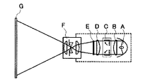
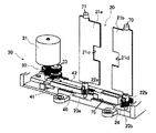
図1は本発明を用いたプロジェクタの概略の構成図であり、図2はその光量調節の概念説明図であり、図3は光量調節装置の全体説明図である。図1においてプロジェクタ装置は光源Aと、この光源Aからの光を平行光線に変換するコンデンサーレンズBと、このレンズBからの光を色光分離するダイクロイックミラーを含む照明光学系Dと、この照明光学系Dからの光を受ける液晶パネルEと、この液晶パネルEを通過した光を投写する投写レンズFとから構成される。この投影光学系は種々の方法が知られ、光源部(光源Aなど)と像形成部(液晶パネルEなど)と投影部(投写レンズFなど)とをケーシング内に適宜の構成で組込んでプロジェクタ装置が構成される。
Preferred embodiments of the present invention will be described below with reference to the drawings.
FIG. 1 is a schematic configuration diagram of a projector using the present invention, FIG. 2 is a conceptual explanatory diagram of the light amount adjustment, and FIG. 3 is an overall explanatory diagram of the light amount adjustment device. In FIG. 1, a projector apparatus includes a light source A, a condenser lens B that converts light from the light source A into parallel rays, an illumination optical system D that includes a dichroic mirror that separates the light from the lens B, and the illumination optical system. It comprises a liquid crystal panel E that receives light from the system D, and a projection lens F that projects the light that has passed through the liquid crystal panel E. Various methods are known for this projection optical system. A light source unit (such as a light source A), an image forming unit (such as a liquid crystal panel E), and a projection unit (such as a projection lens F) are assembled in a casing with an appropriate configuration. A projector device is configured.
このようなプロジェクタ装置に内蔵される光量調節装置Cは例えばコンデンサーレンズBと照明光学系Dとの間に以下の構造で組込まれる。 The light amount adjusting device C built in such a projector device is incorporated between the condenser lens B and the illumination optical system D with the following structure, for example.
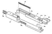
図3に示す光量調節装置Cはプロジェクタ装置の光路Rの周囲を囲む枠組フレーム10に光量調節板20と駆動装置30と伝動機構40とを組込んだユニットとして構成されている。
A light amount adjusting device C shown in FIG. 3 is configured as a unit in which a light
枠組フレーム10は適宜の樹脂材料でプロジェクタ装置に組込む形状に形成され、光路Rの開口部R1を備えている。開口部R1の周側縁には対向する左右側縁に一対の光量調節板21a,21bが開口部R1の開口径を形成するように配置される。この光量調節板21a,21bは樹脂フィルム材の打抜き成形或いは金属板(例えばアルミニウム合金)の薄板を打抜き形成によって形成し黒色の表面処理を施す。この光量調節板21a,21bの形状は光路Rの中心から左右及び上下にほぼ均一な開口が得られるように形成する。
The
つまり光路Rの中心がコンデンサーレンズB及び投写レンズFの中心から割り出され、この光路Rの中心に対し左右及び上下にほぼ均一な開口を形成するように光量調節板21a,21bの形状を定める。図示のものは投影する映像が矩形状である為この光量調節板21a,21bの形状も矩形状に形成してある。そしてこの左右一対の光量調節板21a,21bは枠組フレーム10に回転支軸70,71によって軸受支持されている。枠組フレーム10には光量調節板21a,21bに一体形成された突起状ピンを嵌合する軸受穴が形成してあり、両者が回動自在に軸受嵌合されている。従って左右一対の光量調節板21a,21bは図3矢印方向(光路の進行方向)に回転支軸70及び71を中心に回動し観音開き状に開閉することとなる。
That is, the centers of the optical paths R are determined from the centers of the condenser lens B and the projection lens F, and the shapes of the light
尚上記突起状ピンから構成した回転支軸70と71とは図3に示すように光路Rの対向する周側縁に互いに平行に配置され、光量調節板21a,21bはその形状も開閉動作も左右対称に形成されている。
As shown in FIG. 3, the
前記枠組フレーム10には駆動モータ31が取付けてあり、その駆動回転軸33は光量調節板21a,21bの回転支軸70,71と略平行に位置している。従って光路Rに対し左右両側部に光量調節板21a,21bの回転支軸70,71が平行に配置され、この両支軸に対して駆動回転軸33が平行となるように駆動モータ31が配置されることとなる。図示の駆動モータ31はステッピングモータで構成され、その制御基板(ドライバー回路)50に電源のパルス発生器及びカウンター回路が組込まれている。これ等の制御回路を組込んだ制御基板50も駆動回転軸33と略々平行になるように枠組フレーム10に組込んである。
A
このように光路Rと直交する平面内に左右一対の回転支軸70,71と駆動回転軸33、更に制御基板50もそれぞれ距離を距てて平行(並行)に配置したのは各構成部品の吊めるスペースを出来るだけ小型にする為に割り出した配置であり、光路Rの形状に合わせてこれ等を略々並列に配置すれば良い。
In this way, the pair of left and right
そこで上述の駆動回転軸33と光量調節板21a,21bの回転支軸70,71とを連結する伝動機構について説明する。
Therefore, a description will be given of a transmission mechanism that connects the
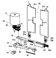
まず駆動回転軸33は駆動モータ31の出力軸に減速ギア32を介して駆動回転軸33に駆動が伝達され、この駆動回転軸33には出力用のピニオン34が設けてある。そしてこのピニオン34に噛合するラック歯車41aを備えた伝動部材40が回転支軸70,71に駆動モータ31の回転を伝達するようになっている。図示の伝動部材40は第1伝動レバー41(以下第1レバーという)と第2伝動レバー42(以下第2レバーという)とで構成され、この2つのレバー部材は互いに結合して一体化されている。第1レバー41にはラック歯車41aが形成され駆動回転軸33のピニオン34と係合し、第2レバー42にはラック歯車42aと42bが設けてあり、ラック歯車42aには光量調節板21aの回転支軸71が、ラック歯車42bには回転支軸70がそれぞれの軸に設けたピニオンと係合することによって連結する。そして第1レバー41と第2レバー42とは互いに小さいストロークで相対的に移動するよう一方の係合突起と他方の長溝が嵌合され両者が連結されている。
First, the
つまり第1レバー41には長溝41dと41eが第2レバー42には突起42dと42eが形成され長溝41dと突起42dが、長溝41eと突起42eがそれぞれ嵌合して、長溝41d,41eのストロークLで第1、第2レバー41、42は相対的に図5左右方向に移動自在となる。そして、第1レバー41と第2レバー42の間には付勢スプリング43が第1レバー41の掛止突起41cと第2レバー42の掛止突起42cとの間に掛け渡してあり、第1、第2レバー41、42はこの付勢スプリング43に抗して前記ストロークL内で相対移動するようになっている。
That is, the
これは第1レバー41を駆動回転軸33のピニオン34で図5左方向に移動すると付勢スプリング43を介して第2レバー42を右方向に移動しこの第2レバー42が後述する光量調節板21a,21bの規制ストッパーに突き当たった後は付勢スプリング43が伸びて、第2レバー42およびこれに歯車連結した光量調節板21a,21bをバネ力で一方向(規制ストッパー側)に付勢する為である。
This is because when the
このように一体化された第1、第2レバー41、42は図4に示すように枠組フレーム10の底部に形成した凹溝状のガイドレール75に嵌合保持され図示左右方向にガイドレール75に沿って移動自在に組込まれる。
The first and
そして、前記第2レバー42にはラック歯車42aと42bが形成され、歯車42aは光量調節板21aの回転支軸71に取付けたピニオン歯車23aと噛合し、他方の歯車42bは光量調節板21bの回転支軸71に取付けたピニオン歯車23bと噛合する歯車24と噛み合うようになっている。この回転支軸71のピニオン歯車23bと噛合する歯車24はフレーム10に軸支した中間軸に取付けてある。従って、第2レバー42が図5左方向に移動すると回転支軸70の歯車23bは中間軸の歯車24を介して時計方向に回転し、回転支軸71の歯車23aは反時計方向に回転することとなる。
Rack gears 42a and 42b are formed on the
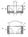
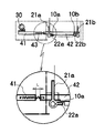
一方、上述の一対の光量調節板21a,21bはそれぞれ回転支軸70,71に支持され枠組フレーム10に回動自在に取付けられているが、この回転支軸70,71には突起22a、22bが設けられている。この突起22a,22bは各支軸を軸承する枠組フレーム10に設けられた規制ストッパー(規制部材)10a,10bによって所定角度範囲で回転する。これを図2に基づいて説明すると、光路Rの対向する側縁部に配置された一対の光量調節板21a,21bは回転支軸70,71を中心に光路Rの進行方向に図(a)の絞り位置と同図(b)の退避位置との間で開閉するように設定する。
On the other hand, the pair of light
従って光量調節板21a,21bが光路Rと略直交する絞り位置で光路Rは最少口径に絞られ通過する光量が最少となり、光量調節板21a,21bが光路Rの進行方向と略平行な退避位置で光路Rは最大口径となり、通過する光量が最大となる。そこで回転支軸70,71をそれぞれ90度範囲で段階的に回動すれば光路Rの光量を調節することが可能となる。
Accordingly, the light
そこで各回転支軸70,71には突起22a,22bが設けてあり、枠組フレーム10には規制ストッパー10a,10bが設けてある。この突起とストッパーとは図7に示すように光量調節板21a,21bが退避位置(全開位置)のとき互いに当接して回転支軸70,71がそれ以上回転するのをストッパーで阻止するようになっている。これと共に回転支軸70,71には第1レバー41と第2レバー42との間に掛け渡した付勢スプリング43が退避位置のとき各支軸70、71を規制ストッパー10a,10b側に付勢力を及ぼすようになっている。従って退避位置(図7(b))のとき光量調節板21a,21bには付勢スプリング43の付勢力で規制ストッパー10a,10b側に付勢され外部からの衝撃が及んでも移動することなくその位置に保持される。
Accordingly, the
そこで駆動装置30の制御について説明するとステッピングモータで構成された駆動装置30はパルス発生回路、電源回路などを組込んだ制御基板50に電気的に接続されている。そして前記伝動部材を構成する第1レバー41にはその位置を検出するポジションセンサ44が設けられている。図5に示すようにホトカプラーで構成したポジションセンサ44が枠組フレーム10に取付けられ、第1レバー41には突起からなるアクチュエータ41bが設けられている。そして光量調節板21a,21bが絞り位置に位置するときホームポジションとしてポジションセンサ44がアクチュエータ41bでONするようになっている。
Therefore, the control of the driving
そこで図4の状態で駆動モータ31を減速ギア32を介して駆動回転軸33のピニオン歯車34を反時計方向に回転するとこれと噛したラック歯車41aは第1レバー41を左方向に移動し、付勢スプリング43を介して第2レバー42も左方向に移動する。すると第2レバー42に形成されているラック歯車42aは回転支軸71のピニオン歯車23aを反時計方向に回転し、光量調節板21aを絞り装置から退避位置に回転支軸71を中心に回転する。同様に第2レバー42に形成されているラック歯車42bは中間軸の歯車24を介して回転支軸70のピニオン歯車23bを時計方向に回転し、光量調節板21bを絞り位置から退避位置に回転支軸70を中心に回転する。そして各回転支軸70,71に形成された突起22a,22bが規制ストッパー10a,10bに係合してそれ以上の回転が阻止されると第2レバー42は静止し、一方第1レバー41は更に左方向に移動し、付勢スプリング43は伸びて蓄勢される。この第1レバー41のオーバラン量は予め長溝41dによって形成したストロークLの範囲内に設定してある。この状態で駆動モータ31への通電を断つとステッピングモータは所定の位相角度範囲で停止し、ディテントトルクが作用し、付勢スプリング43に蓄勢された付勢力は第2レバー42を常に図5左側に移動する力として作用する。従って左右の光量調節板21a,21bには常に図示矢印方向の付勢力が作用することとなる。
Therefore, when the
尚、前記第1レバー41と第2レバー42との間のストロークLは駆動モータの位相角度より大きく設定してある。この場合駆動モータとしてステッピングモータを用いない場合にはモータ及び減速ギアの負荷によって駆動モータ31を静止させるようにする。
The stroke L between the
次に駆動モータ31を逆転させ駆動回転軸33を図5反時計方向に回転すると第1のレバー41は図5右方向に移動し、ストロークLの移動の後第1レバー41の長溝41dの縁部と第2レバー42の突起42dが係合して第2レバー42も右方向に移動する。この第2レバー42の右方向への移動で回転支軸71は時計方向に回転支軸70は反時計方向に回転し、光量調節板21a,21bは図5に示す絞り位置に復帰する。この絞り位置で光量調節板21a,21bは駆動モータ30のディテントルク或いは減速歯車の負荷によってその姿勢が維持される。
Next, when the
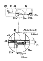
以上説明した伝動部材40は第1レバー41と第2レバー42との2つのスライド部材で構成され、退避位置でその一方をオーバランさせてスプリングに蓄勢し、一対の光量調節板を退避位置の規制ストッパーに弾圧付勢するものを説明したが、図10に示す構造であっても良い。
The
図10において光路Rの対向する側縁部に一対の光量調節板21a,21bをそれぞれ回転支軸70,71に前述と同様に図示しない枠組フレームに取付ける。また、駆動装置30もステッピングモータ31、減速歯車32、駆動回転軸33及びピニオン歯車34を前述のものと同様に枠組フレームに取付ける。
In FIG. 10, a pair of light
従って回転支軸70と71とは光路Rを挟んで左右に平行に配置され駆動回転軸33もこの両支軸70,71に対し略平行に配置されることとなる。そこで距離を距てて略平行に配置されたこれらの回転支軸及び回転軸に対し略々直交する方向に移動自在の伝動部材80を設ける。この伝動部材80は図示しないが枠組フレームの下枠に形成したレールに係合して図10左右方向に移動自在に取付ける。そして伝動部材80にはラック歯車81と82及びラック歯車83を設け、駆動回転軸33のピニオン歯車34とラック歯車81が噛合し、回転支軸71のピニオン歯車23aとラック歯車82が噛合し、回転支軸70のピニオン歯車23bとラック歯車83とを噛合する。
Therefore, the
このときピニオン歯車23aとピニオン歯車23bとは逆方向に回転するように伝動部材80にラック歯車82と83を形成する。図示のものはレバー状の伝動部材80の片面にラック歯車82を他面にラック歯車83を形成してある。
At this time, rack gears 82 and 83 are formed on the
一方回転支軸70と71には前述のものと同様に突起22a,22bが形成してあり、図10(b)に示すように光量調節板が退避した位置に規制部材84が枠組フレーム10に設けてある。そして両光量調節板の突起22a,22bは軟磁性材図示のものは鉄片で形成し、規制部材84はマグネットで形成してある。従って突起22a,22bはマグネットから成る規制部材84でそれ以上の回動を阻止されると共にマグネットの磁力でこの位置に保持されることとなる。
On the other hand,
尚規制部材84は枠組フレーム10にスプリング85を作用させて少許の範囲で図10(b)上下方向に移動可能に取付けてある。そこで図10(a)の状態で駆動モータ31を駆動して駆動回転軸33のピニオン歯車を図示時計方向に回転すると、これと噛合したラック歯車81を介して伝動部材80は図左側に移動する。するとラック歯車82に噛合した回転支軸71のピニオン歯車23aは反時計方向に回転して光量調節板21aを図示の絞り位置から退避位置に移動する。同様にラック歯車83に噛合した回転支軸70のピニオン歯車23bは時計方向に回転して光量調節板21bを退避位置に移動する。
The restricting
上述の伝動部材80には前述の第1レバーと同様にポジションセンサ84が枠組フレームに取付けたホトセンサーで構成してあり、伝動部材80側に突起85a,85bから成るアクチュエータが設けてある。そして突起85aは光量調節板が絞り位置のときセンサーをONし、突起85bは光量調節板が退避位置のときセンサーをONするように配置されている。
Like the first lever, the
従って駆動モータ31を突起85bがセンサー84をONしたとき停止する。すると回転支軸70,71の突起22a,22bは規制部材84と当接してそれ以上の回転が阻止され停止する。この時の駆動モータの停止タイミングと突起22a,22bが規制部材84に当接する位置のバラつきはスプリング85で吸収され、規制部材84の磁力で光量調節板は退避位置に保持される。
Therefore, the
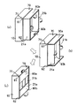
以上説明した光量調節板は光路Rの左右或いは上下に一対配置し、光路Rの進行方向に観音開き状に開閉する場合を示したが光路Rの左右に一対更に上下に一対形成するようにしても良く、これを図12に従って説明する。 A pair of the light quantity adjusting plates described above is arranged on the left and right or top and bottom of the optical path R and opened and closed in a double-sided manner in the traveling direction of the optical path R. This will be described with reference to FIG.
図示のものは光路Rの左右に光量調節板21a,21bが対向する位置に設けてあり、光路Rの上下に光量調節板60a,60bが対向する位置に設けてある。光量調節板21a,21bは前述のものと同様に枠組フレーム10に回転支軸70,71で回動自在に支持してあり、光量調節板60a,60bも同様に枠組フレーム10に回転支軸61,62で回転自在に支持してある。
The illustrated one is provided at a position where the light
そこで上下の光量調節板60a,60bは左右の光量調節板21a,21bにその端部が図10(a)のように係合していて左右の光量調節板21a,21bを回動するとこれに連動して上下の光量調節板60a,60bが回動する関係になっている。
Therefore, when the upper and lower light
そこで上下の光量調節板60a,60bにはそれぞれの回転支軸61,62との間に図示矢印と反対方向に回動するようにコイルスプリングが設けてあり、左右の光量調節板21a,21bには前述の構造の駆動回転軸及び伝動部材が連結してある。従って前述のものと同様の制御で左右の光量調節板21a,21bを開閉すると、これと連動して上下の光量調節板60a,60bが開閉することとなる。
Therefore, the upper and lower light
次にプロジェクタ装置の構成について説明すると、図1にその概略レイアウト構成を示すように装置ケーシングにハロゲンランプなどの光源ランプと、この光源の光を乱反射するリフレクターなどから光源Aを内蔵し、この光源Aからの光をコンデンサーレンズBで平均化して光路Rを形成する。光路Rの光は集光レンズDを介して液晶パネルEに照射される。液晶パネルはR・G・B3原色のフィルタで3層に形成され、映像信号を受けて画像を形成する。従ってこの液晶パネルが像形成部を構成することとなり、光源Aからの光を受けて投写レンズFからスクリーンG上に画像を投影する。そして投写レンズFには焦点合わせのフォーカシング機構が組み込まれている。そこで前述の光量調節装置をコンデンサーレンズBと集光レンズDの間の光路Rに組込み光の進行方向に前記光量調節板21a,21bが開閉するように配置する。
Next, the configuration of the projector apparatus will be described. As shown in FIG. 1, a light source lamp such as a halogen lamp and a reflector that diffusely reflects the light from the light source is built in the apparatus casing. The light from A is averaged by the condenser lens B to form an optical path R. The light in the optical path R is applied to the liquid crystal panel E through the condenser lens D. The liquid crystal panel is formed in three layers with R, G, and B3 primary color filters and receives an image signal to form an image. Accordingly, the liquid crystal panel constitutes an image forming unit, and receives an image from the light source A and projects an image from the projection lens F onto the screen G. The projection lens F incorporates a focusing mechanism. Therefore, the above-described light amount adjusting device is installed in the optical path R between the condenser lens B and the condenser lens D so that the light
一方装置のケーシングには外部の明るさを検出する照度センサーを設ける。この照度センサーは投写レンズからの光がスクリーンGで反射した光を検出するか、投写レンズからの投影光以外の外部光を検出するか、或いはその両者を検出して明るさの差を検知するかいずれの方法であっても良い。照度センサーとしては光電変換素子を用いて光量を電気的に検出するポジションセンサ或いはCCDなどのセンサーを用いれば良い。 On the other hand, an illuminance sensor that detects external brightness is provided in the casing of the apparatus. This illuminance sensor detects light reflected from the screen G by the light from the projection lens, detects external light other than the projection light from the projection lens, or detects both to detect a difference in brightness. Either method may be used. As the illuminance sensor, a position sensor that electrically detects the amount of light using a photoelectric conversion element or a sensor such as a CCD may be used.
一方プロジェクタ装置の制御部には液晶パネルに画像信号を送る映像信号処理部がICチップなどで構成され外部のコンピュータその他の映像機器と接続されている。この制御部にはコントローラが組込まれフォーカシング調整、或いは画隔を調整する機能と同時に操作パネルが結線されている。そこで操作パネルに設けた明るさ調整釦を使用者が操作するかこれと同時に外部光を検出する照度センサーからの検出信号で明るさを自動調整するように構成する。 On the other hand, a video signal processing unit for sending an image signal to the liquid crystal panel is constituted by an IC chip or the like and connected to an external computer or other video equipment in the control unit of the projector apparatus. A controller is incorporated in this control unit, and an operation panel is connected simultaneously with a function of adjusting a focusing or adjusting a picture interval. Therefore, the brightness is adjusted automatically by the detection signal from the illuminance sensor that detects the external light at the same time when the user operates the brightness adjustment button provided on the operation panel.
次にその作用を説明すると、プロジェクタ装置の電源を投入し映像をスクリーン上に投写する。この映像を使用者が見てコントロールパネルの明るさ調整釦を操作する。或いは外部光を照度センサーで検出し予め設定した明るさ調整を実行する。若しくは照度センサーで外部光とスクリーンで反射した投影光の両者を検出して光量の差から明るさ調整を実行する。このようにスクリーン上の画面の明るさの調整がコントローラで指示されると、光量調節装置は以下の動作を行う。 Next, the operation will be described. The projector apparatus is turned on to project an image on the screen. The user views this video and operates the brightness adjustment button on the control panel. Alternatively, external light is detected by an illuminance sensor and preset brightness adjustment is executed. Alternatively, both the external light and the projection light reflected by the screen are detected by the illuminance sensor, and the brightness adjustment is executed from the difference in the light amount. As described above, when the controller instructs to adjust the brightness of the screen on the screen, the light amount adjusting device performs the following operation.
まず前述の駆動装置30は伝動部材(前述の第1レバー41又は伝動部材80)がホームポジション位置で静止した状態にある。このホームポジションは図示のものは退避位置に設定してあるが、絞り位置或いは絞り位置と退避位置との中間点でもいずれでも良い。この予め設定されたホームポジションから前記手動(マニュアル調整)か自動調整かいずれかの信号を受けて所定パルス数の起動信号を制御回路50が受け、パルス電源を駆動モータ31に供給する。この電源の供給で駆動モータは所定角度回転する。すると駆動回転軸33のピニオン歯車34が所定角度回転し、これと噛合したラック歯車41aを駆動し伝動部材(第1レバー41若しくは伝動レバー80)を所定量移動する。この伝動部材の移動で回転支軸70,71が所定角度反対方向に回転し、一対の光量調節板を所定角度移動する。この光量調節板の所定角度の移動によって光路Rの光量は大小に調節され、スクリーンに投影される影像が明暗調整されることとなる。
First, the
かかる過程で本発明は、光源からの光をスクリーン上に投影する光路Rの対向する側縁部に一対の光量調節板を光路の進行方向に回動するよう回転支軸に支持してあるから羽根状の光量調節板は光路の進行方向に移動スペースを吊めることとなり、図2(a),(b)に示すような移動軌跡を演く。この時光量調節板は図2(a)の絞り位置では駆動モータ31に供給電源がOFFされた後もモータのディテントトルク或いは減速歯車列の負荷によってその位置に保持される。この時外部から衝撃などの力が及んでも、図11(b)の状態に光量調節板は光路Rとほぼ直交する方向であり、仮に外部からの不本意な衝撃によって角度θ振れたとしても光路Rの光量に及ぼす影響はΔ1となり、大きな光量の調整誤差を招くことがない。
In this process, the present invention has a pair of light amount adjusting plates supported on the rotating support shaft so as to rotate in the traveling direction of the optical path at the opposite side edges of the optical path R for projecting light from the light source onto the screen. The blade-shaped light amount adjusting plate suspends a moving space in the traveling direction of the optical path, and exhibits a moving locus as shown in FIGS. At this time, the light quantity adjusting plate is held at that position by the detent torque of the motor or the load of the reduction gear train even after the power supply to the
一方光量調節板が図11(a)の退避位置では外部から衝撃が作用して角度θ振れた場合には光路Rの光量に及ぼす影響はΔ2となり大きな光量の調整誤差を招く。ところが光量調節板は規制ストッパー(規制部材)10a,10bに一方向の回転を阻止され、更に保持手段、図3の構成にあっては付勢スプリング43の作用で、また図10の構成にあってはマグネット84の吸引力で規制部材の位置に保持されガタつきなどで移動する恐れがない。
On the other hand, when the light amount adjusting plate is moved at an angle θ due to an external impact at the retracted position in FIG. 11A, the influence on the light amount of the optical path R is Δ2, which causes a large light amount adjustment error. However, the light quantity adjustment plate is prevented from rotating in one direction by the restriction stoppers (restriction members) 10a and 10b, and is further supported by the holding means, the urging
A 光源
B コンデンサーレンズ
C 光量調節装置
D 照明光学系
E 液晶パネル
F 投写レンズ
10 枠組フレーム
10a,10b 規制ストッパー(規制部材)
21a,21b 光量調節板
30 駆動装置
31 駆動モータ
33 駆動回転軸
40 伝動部材
41 第1伝動レバー
41a ラック歯車
41b アクチュエータ
41c 掛止突起
41d 長溝
41e 長溝
42 第2伝動レバー
42a ラック歯車
42b ラック歯車
42c 掛止突起
42d 突起
42e 突起
43 付勢スプリング
44 ポジションセンサ
60a,60b 光量調節板
70,71 回転支軸
A Light source B Condenser lens C Light quantity adjusting device D Illumination optical system E Liquid crystal panel
21a, 21b Light
Claims (6)
上記光量調節板を上記光路の進行方向に揺動可能に支持する上記光路の対向する側縁部に配置された一対の回転支軸と、
上記光量調節板を上記光路内に進入した絞り位置と上記光路外に退避した退避位置との間で開閉駆動する駆動手段とを備え、
上記退避位置で上記光量調節板回動を規制する規制部材と、この規制部材に上記光量調節板を保持する保持手段とを設けたことを特徴とする光量調節装置。 At least a pair of light amount adjusting plates disposed on the peripheral edge of the optical path for projecting light from the light source;
A pair of rotating support shafts disposed on opposite side edges of the optical path for supporting the light amount adjusting plate so as to be swingable in the traveling direction of the optical path;
Driving means for opening and closing the light amount adjustment plate between a diaphragm position that enters the optical path and a retracted position that is retracted outside the optical path;
A light amount adjusting device comprising: a restricting member for restricting rotation of the light amount adjusting plate at the retracted position; and a holding means for holding the light amount adjusting plate on the restricting member.
前記保持手段をこのストッパー部材に光量調節板を付勢するスプリング、マグネットなどの付勢部材で構成したことを特徴とする請求項1記載の光量調節装置。 The restriction member is constituted by a stopper member that prevents the light amount adjustment plate from rotating more than a predetermined angle,
2. The light quantity adjusting device according to claim 1, wherein the holding means is constituted by an urging member such as a spring or a magnet for urging the light quantity adjusting plate to the stopper member.
この駆動源の駆動力を前記光量調節板に伝達する伝動部材とで構成し、
この伝動部材に前記光量調節板を規制部材に付勢する付勢手段を設けたことを特徴とする請求項1記載の光量調節装置。 The drive means is a motor or other drive source;
It is composed of a transmission member that transmits the driving force of this driving source to the light amount adjusting plate,
2. The light quantity adjusting device according to claim 1, wherein the transmission member is provided with an urging means for urging the light quantity adjusting plate to the regulating member.
上記光量調節板を上記光路の進行方向に揺動可能に支持する上記光路の対向する側縁部に配置された一対の回転支軸と、
上記光量調節板を上記光路内に進入した絞り位置と上記光路外に退避した退避位置との間で開閉駆動する駆動手段と、
上記退避位置で上記光量調節板の所定角度以上の回動を阻止する規制部材とを備え、
上記駆動手段を駆動回転軸を有するモータと、
この駆動回転軸の回転で所定量往復運動する第1の伝動レバー部材と、
この第1の伝動レバー部材の運動を上記光量調節板に伝達する第2の伝動レバー部材とで構成し、
上記第1の伝動レバー部材と第2の伝動レバー部材との間に上記光量調節板を退避位置で上記規制部材に付勢する付勢手段を設けたことを特徴とする光量調節装置。 At least a pair of light amount adjusting plates disposed on the peripheral edge of the optical path for projecting light from the light source;
A pair of rotating support shafts disposed on opposite side edges of the optical path for supporting the light amount adjusting plate so as to be swingable in the traveling direction of the optical path;
Driving means for opening and closing the light amount adjusting plate between an aperture position that enters the optical path and a retracted position that is retracted outside the optical path;
A restricting member that prevents the light amount adjusting plate from rotating more than a predetermined angle at the retracted position;
A motor having a driving rotary shaft as the driving means;
A first transmission lever member that reciprocates a predetermined amount by the rotation of the drive rotation shaft;
The second transmission lever member that transmits the movement of the first transmission lever member to the light amount adjustment plate,
A light quantity adjusting device, characterized in that an urging means is provided between the first transmission lever member and the second transmission lever member to urge the light quantity adjusting plate to the regulating member at a retracted position.
光源からの光を上記像形成手段に照射して投射する投影光路と、
この投影光路の対向する側縁部に配置された少なくとも一対の光量調節板と、
上記光量調節板を上記投影光路の進行方向に揺動可能に支持する上記光路の対向する側縁部に配置された一対の回転支軸と、
上記光量調節板を上記投影光路内に進入した絞り位置と上記投影光路外に退避した退避位置との間で開閉駆動する駆動手段とを備え、
上記退避位置で上記光量調節板の回動を規制する規制部材と、
この規制部材に上記光量調節板を保持する保持手段とを設けたことを特徴とするプロジェクタ。 Image forming means for forming an image;
A projection optical path for projecting the image forming means by irradiating light from a light source;
At least a pair of light amount adjusting plates disposed on opposite side edges of the projection optical path;
A pair of rotating support shafts disposed on opposite side edges of the optical path for supporting the light amount adjustment plate so as to be swingable in the traveling direction of the projection optical path;
Driving means for opening and closing the light amount adjusting plate between a diaphragm position that has entered the projection optical path and a retracted position that has been retracted out of the projection optical path;
A restricting member for restricting rotation of the light amount adjusting plate at the retracted position;
A projector characterized in that a holding means for holding the light amount adjusting plate is provided on the regulating member.
Priority Applications (2)
| Application Number | Priority Date | Filing Date | Title |
|---|---|---|---|
| JP2004108719A JP2005292531A (en) | 2004-04-01 | 2004-04-01 | Light quantity adjusting device and projector using the same |
| US11/060,620 US7344255B2 (en) | 2004-04-01 | 2005-02-18 | Light amount adjusting apparatus and projector using the same |
Applications Claiming Priority (1)
| Application Number | Priority Date | Filing Date | Title |
|---|---|---|---|
| JP2004108719A JP2005292531A (en) | 2004-04-01 | 2004-04-01 | Light quantity adjusting device and projector using the same |
Publications (1)
| Publication Number | Publication Date |
|---|---|
| JP2005292531A true JP2005292531A (en) | 2005-10-20 |
Family
ID=35325504
Family Applications (1)
| Application Number | Title | Priority Date | Filing Date |
|---|---|---|---|
| JP2004108719A Pending JP2005292531A (en) | 2004-04-01 | 2004-04-01 | Light quantity adjusting device and projector using the same |
Country Status (1)
| Country | Link |
|---|---|
| JP (1) | JP2005292531A (en) |
Cited By (2)
| Publication number | Priority date | Publication date | Assignee | Title |
|---|---|---|---|---|
| US8262231B2 (en) | 2008-03-10 | 2012-09-11 | Seiko Epson Corporation | Light control device, lighting device, and projector for controlling transmission amount of light emitted from an emission area by use of curved light shielding members |
| WO2013069158A1 (en) * | 2011-11-11 | 2013-05-16 | Necディスプレイソリューションズ株式会社 | Projector and aperture control method |
Citations (3)
| Publication number | Priority date | Publication date | Assignee | Title |
|---|---|---|---|---|
| JPS5271231A (en) * | 1975-12-11 | 1977-06-14 | Fuji Photo Film Co Ltd | Double blade type shutter means |
| JPH07253619A (en) * | 1992-01-29 | 1995-10-03 | Deutsche Thomson Brandt Gmbh | Video camera |
| JP2001228508A (en) * | 2000-02-18 | 2001-08-24 | Canon Inc | Barrier device and camera |
-
2004
- 2004-04-01 JP JP2004108719A patent/JP2005292531A/en active Pending
Patent Citations (3)
| Publication number | Priority date | Publication date | Assignee | Title |
|---|---|---|---|---|
| JPS5271231A (en) * | 1975-12-11 | 1977-06-14 | Fuji Photo Film Co Ltd | Double blade type shutter means |
| JPH07253619A (en) * | 1992-01-29 | 1995-10-03 | Deutsche Thomson Brandt Gmbh | Video camera |
| JP2001228508A (en) * | 2000-02-18 | 2001-08-24 | Canon Inc | Barrier device and camera |
Cited By (2)
| Publication number | Priority date | Publication date | Assignee | Title |
|---|---|---|---|---|
| US8262231B2 (en) | 2008-03-10 | 2012-09-11 | Seiko Epson Corporation | Light control device, lighting device, and projector for controlling transmission amount of light emitted from an emission area by use of curved light shielding members |
| WO2013069158A1 (en) * | 2011-11-11 | 2013-05-16 | Necディスプレイソリューションズ株式会社 | Projector and aperture control method |
Similar Documents
| Publication | Publication Date | Title |
|---|---|---|
| JP5044234B2 (en) | Projection display | |
| US7344255B2 (en) | Light amount adjusting apparatus and projector using the same | |
| JP4254442B2 (en) | Lighting device and projector | |
| JP5002923B2 (en) | Projection-type image display device | |
| US8317418B2 (en) | Focal plane shutter and imaging apparatus including the same | |
| EP1889476B1 (en) | Shutter opening and closing apparatus for beam projector | |
| US7182470B2 (en) | Light amount control apparatus and projector apparatus using the same | |
| US7744227B2 (en) | Projector including a turn table for shifting a lens barrel | |
| US10670949B2 (en) | Projector with attitude adjustment apparatus | |
| US8189253B2 (en) | Shutter device and drive method | |
| JP2003270511A (en) | Full aperture regulator | |
| JP2005292532A (en) | Light quantity adjustment apparatus and projector using the same | |
| JP2004317988A (en) | Barrel support device and projection display device | |
| WO2010113259A1 (en) | Dimming device and projector-type display apparatus comprising the same | |
| JP2005292764A (en) | Light quantity adjusting device and projector using the same | |
| JP2005292531A (en) | Light quantity adjusting device and projector using the same | |
| JP2006078787A (en) | Projector apparatus | |
| JP5847438B2 (en) | Light control device | |
| JP2531407Y2 (en) | Motor driven shutter | |
| JP2006078784A (en) | Device for adjusting light quantity, and projector device using the same | |
| JP2006078786A (en) | Device for adjusting light quantity, and projector device using the same | |
| JP2005164819A (en) | Diaphragm for controlling light source | |
| JP5926621B2 (en) | Lens shift mechanism and projection display device | |
| JP2006078785A (en) | Device for adjusting light quantity, and projector device using the same | |
| JP3965235B2 (en) | Camera aperture device |
Legal Events
| Date | Code | Title | Description |
|---|---|---|---|
| A621 | Written request for application examination |
Free format text: JAPANESE INTERMEDIATE CODE: A621 Effective date: 20070226 |
|
| A977 | Report on retrieval |
Free format text: JAPANESE INTERMEDIATE CODE: A971007 Effective date: 20091126 |
|
| A131 | Notification of reasons for refusal |
Free format text: JAPANESE INTERMEDIATE CODE: A131 Effective date: 20091203 |
|
| A02 | Decision of refusal |
Free format text: JAPANESE INTERMEDIATE CODE: A02 Effective date: 20100326 |