JP2005292494A - Housing/carrying case for semiconductor device producing member, housing apparatus, and air supply control method for housing apparatus - Google Patents
Housing/carrying case for semiconductor device producing member, housing apparatus, and air supply control method for housing apparatus Download PDFInfo
- Publication number
- JP2005292494A JP2005292494A JP2004107895A JP2004107895A JP2005292494A JP 2005292494 A JP2005292494 A JP 2005292494A JP 2004107895 A JP2004107895 A JP 2004107895A JP 2004107895 A JP2004107895 A JP 2004107895A JP 2005292494 A JP2005292494 A JP 2005292494A
- Authority
- JP
- Japan
- Prior art keywords
- air
- semiconductor device
- container body
- air supply
- housing
- Prior art date
- Legal status (The legal status is an assumption and is not a legal conclusion. Google has not performed a legal analysis and makes no representation as to the accuracy of the status listed.)
- Pending
Links
- 239000004065 semiconductor Substances 0.000 title claims abstract description 50
- 238000000034 method Methods 0.000 title claims abstract description 12
- 238000007599 discharging Methods 0.000 claims abstract description 6
- 238000004519 manufacturing process Methods 0.000 claims description 47
- 239000000126 substance Substances 0.000 abstract 1
- 230000032258 transport Effects 0.000 description 22
- 239000000428 dust Substances 0.000 description 11
- 238000012423 maintenance Methods 0.000 description 3
- OKTJSMMVPCPJKN-UHFFFAOYSA-N Carbon Chemical compound [C] OKTJSMMVPCPJKN-UHFFFAOYSA-N 0.000 description 1
- 229910052799 carbon Inorganic materials 0.000 description 1
- 238000001914 filtration Methods 0.000 description 1
- 230000002093 peripheral effect Effects 0.000 description 1
- 239000000088 plastic resin Substances 0.000 description 1
- 239000004417 polycarbonate Substances 0.000 description 1
- 229920000515 polycarbonate Polymers 0.000 description 1
Images
Landscapes
- Preparing Plates And Mask In Photomechanical Process (AREA)
- Exposure And Positioning Against Photoresist Photosensitive Materials (AREA)
- Packaging Frangible Articles (AREA)
- Container, Conveyance, Adherence, Positioning, Of Wafer (AREA)
- Exposure Of Semiconductors, Excluding Electron Or Ion Beam Exposure (AREA)
Abstract
Description
この発明は、ホトマスク等の半導体装置製造用部材を収納する収納・運搬ケース、収納ケースにエアを供給する収納装置及び、この収納装置のエア供給制御方法に関する。 The present invention relates to a storage / transport case for storing a semiconductor device manufacturing member such as a photomask, a storage device for supplying air to the storage case, and an air supply control method for the storage device.
周知のように、ホトマスク等の半導体装置製造用部材を取り扱うためには、塵埃等を極力除去するため、各種の塵埃除去手段を講じるようにしている。
例えば、従来、半導体装置製造用部材に塵埃が付着することを防止するための手段として、半導体装置製造用部材をケース内に収納して、収納された全てのケース内にエアを常時供給する半導体装置製造部材の収納装置が知られている(特許文献1参照)。
また、半導体装置製造用部材に塵埃が付着することを防止する手段として、半導体装置製造部材を収納する底皿をカーボンが添加されたポリカーボネードにより構成し、上蓋を非伝導プラスチック樹脂により構成された収納ケースが知られている(特許文献2参照)。
このように構成され収納ケースにおいては、上蓋が帯電することにより塵埃が上蓋に静電吸着される。
For example, conventionally, as a means for preventing dust from adhering to a semiconductor device manufacturing member, a semiconductor device manufacturing member is housed in a case, and air is constantly supplied into all the stored cases. A storage device for an apparatus manufacturing member is known (see Patent Document 1).
Also, as means for preventing dust from adhering to the semiconductor device manufacturing member, the bottom plate for storing the semiconductor device manufacturing member is made of polycarbonate added with carbon, and the upper lid is made of nonconductive plastic resin. A case is known (see Patent Document 2).
In the storage case configured as described above, dust is electrostatically attracted to the upper lid by charging the upper lid.
ところで、上記従来の半導体製造用部材の収納装置においては、収納された全てのケース内にエアを供給するため、装置本体の構成が複雑なものとなり、また、維持するための費用も高額となるという問題があった。
さらに、上記従来の半導体装置製造用部材の収納装置においては、ケースの一箇所からエアを供給するため、エアが半導体装置製造用部材の表面を十分に流れ難いという問題があった。
また、上記従来の収納ケースにおいては、上蓋の帯電がなくなると、上蓋に吸着していた塵埃が落下して、半導体装置製造用部材の表面に付着するという問題があった。
By the way, in the conventional storage apparatus for semiconductor manufacturing members, air is supplied into all the stored cases, so that the structure of the apparatus main body becomes complicated, and the cost for maintaining the apparatus becomes high. There was a problem.
Furthermore, in the conventional semiconductor device manufacturing member storage device, since air is supplied from one place of the case, there is a problem that it is difficult for air to sufficiently flow on the surface of the semiconductor device manufacturing member.
Further, in the conventional storage case, there is a problem that when the upper lid is not charged, the dust adsorbed on the upper lid falls and adheres to the surface of the semiconductor device manufacturing member.
この発明は、このような事情を考慮してなされたもので、その目的は、収納された半導体装置製造部材の表面にエアを良好に流すことにより、半導体装置製造用部材の表面に塵埃が付着することを確実に防止でき、また、簡易な構成とすることができ、さらに、維持費用を低廉なものとすることができる半導体装置製造用部材の収納・運搬ケース、収納装置及び、この収納装置のエア供給制御方法を提供することにある。 The present invention has been made in consideration of such circumstances, and its purpose is to allow dust to adhere to the surface of the semiconductor device manufacturing member by allowing air to flow well over the surface of the stored semiconductor device manufacturing member. The semiconductor device manufacturing member storage / transport case, the storage device, and the storage device can be surely prevented from occurring, can have a simple configuration, and can be maintained at low cost. An air supply control method is provided.
請求項1に記載された発明は、半導体装置製造用部材を開口部から収納可能とする容器本体と、該容器本体の前記開口部を閉塞する蓋体とを備えてなり、前記容器本体にはその内部にエアを供給可能とするエア供給機構が設けられ、前記蓋体には前記容器本体内部のエアを排出可能とするエア排出機構が設けられていることを特徴とする。 The invention described in claim 1 is provided with a container main body that can accommodate the semiconductor device manufacturing member from the opening, and a lid that closes the opening of the container main body. An air supply mechanism capable of supplying air is provided therein, and the lid body is provided with an air discharge mechanism capable of discharging air inside the container body.
この発明に係る半導体装置製造用部材の収納・運搬によれば、装置本体内に半導体装置製造用部材を収納して、蓋体を閉じ、エアを容器本体内に供給することにより、容器本体内の圧力を一定圧力以上に確保することによって、蓋体を開口した場合においても、半導体装置製造部材の表面に塵埃の付着が防止される。 According to the storage and transportation of the semiconductor device manufacturing member according to the present invention, the semiconductor device manufacturing member is stored in the device main body, the lid is closed, and air is supplied into the container main body. By ensuring the pressure at a certain pressure or more, even when the lid is opened, the adhesion of dust to the surface of the semiconductor device manufacturing member is prevented.
請求項2に記載された発明は、請求項1に記載された半導体装置製造用部材の収納・運搬ケースにおいて、前記エア供給機構は、前記容器本体に設けられ、該容器本体の内外間を連通させる第1のエア流路と、該エア流路に設けられ、外部から該容器本体へエアの流通を許し、その逆方向への流通を阻止する第1の逆止弁とを備えてなり、前記エア排出機構は、前記蓋体に設けられ、該容器本体の内外間を連通させる第2のエア流路と、該第2の流路に設けられ、該容器本体内の圧力が一定値以上になったときに該容器本体内のエアを外部に排出する第2の逆止弁とを備えてなることを特徴とする。 According to a second aspect of the present invention, in the housing / transporting case for a semiconductor device manufacturing member according to the first aspect, the air supply mechanism is provided in the container body, and communicates between the inside and the outside of the container body. A first air flow path that is provided, and a first check valve that is provided in the air flow path, allows air to flow from the outside to the container body, and blocks flow in the opposite direction. The air discharge mechanism is provided in the lid, and is provided in the second air flow path communicating between the inside and the outside of the container main body, and in the second flow path, and the pressure in the container main body is a predetermined value or more. And a second check valve that discharges the air in the container body to the outside.
この発明に係る製造装置によれば、第1のエア流路に設けられた第1の逆止弁が、容器本体内のエアが外部に排出されることを防止すると共に、第2の流路に設けられた第2の逆止弁が容器本体内の圧力が一定値以上となると、エアを外部に排出することにより、容器本体内の内圧が一定圧力に保持される。 According to the manufacturing apparatus of the present invention, the first check valve provided in the first air flow path prevents the air in the container body from being discharged to the outside, and the second flow path. When the pressure in the container main body becomes equal to or higher than a certain value by the second check valve provided in the container, the internal pressure in the container main body is maintained at a constant pressure by discharging air to the outside.
請求項3に記載された発明は、請求項1又は2に記載された半導体装置製造用部材の収納・運搬ケースと、該半導体装置製造用部材の収納・運搬ケースの前記エア供給機構に接続されて前記容器本体内にエアを供給するエア供給装置を備えてなり、前記エア供給装置は、該容器本体内にエアを供給するポンプと、該容器本体内の圧力を検出するセンサと、該センサの出力にも基づいて前記ポンプの駆動を制御する制御部とを備えてなることを特徴とする。 The invention described in claim 3 is connected to the housing / transport case of the semiconductor device manufacturing member described in claim 1 or 2 and the air supply mechanism of the storage / transport case of the semiconductor device manufacturing member. An air supply device for supplying air into the container body, the air supply device including a pump for supplying air into the container body, a sensor for detecting the pressure in the container body, and the sensor And a control unit for controlling the driving of the pump based on the output of the above.
この発明に係る収納装置によれば、エア供給装置のポンプが容器本体内にエアを供給し、制御部が、圧力センサの出力に基づいてポンプを駆動することにより、容器本体内の内圧が所定の圧力とされる。 According to the storage device of the present invention, the pump of the air supply device supplies air into the container body, and the control unit drives the pump based on the output of the pressure sensor, so that the internal pressure in the container body is predetermined. Of pressure.
請求項4に記載された発明は、請求項3に記載された半導体装置製造用部材の収納装置において、前記ポンプにより供給されるエアを前記半導体装置製造用部材の収納・運搬ケース方向又は外部へ導く切換弁を備え、前記ポンプの駆動の制御に代えて前記切換弁を制御するように構成されていることを特徴とする。 According to a fourth aspect of the present invention, in the storage device for a semiconductor device manufacturing member according to the third aspect, the air supplied by the pump is directed toward or outside the storage / transport case of the semiconductor device manufacturing member. A switching valve for guiding is provided, and the switching valve is controlled instead of controlling the driving of the pump.
この発明に係る収納装置によれば、制御部が切換弁を制御して、ポンプにより供給されるエアを外部に逃がすことによって、容器内の圧力が一定なものとされる。 According to the storage device of the present invention, the control unit controls the switching valve to release the air supplied by the pump to the outside, whereby the pressure in the container is made constant.
請求項5に記載された発明は、請求項3又は4に記載された半導体装置製造用部材の収納装置において、前記半導体装置製造用部材の収納・運搬ケースに対し、前記エア供給装置が着脱自在に接続されるように構成されていることを特徴とする。 According to a fifth aspect of the present invention, in the storage device for a semiconductor device manufacturing member according to the third or fourth aspect, the air supply device is detachable from the storage / transport case of the semiconductor device manufacturing member. It is comprised so that it may be connected to.
この発明に係る収納装置によれば、容器本体内の内圧が所定の内圧とされた半導体装置製造部材の収納・運搬ケースと、エア供給装置とから分離することができる。 The storage device according to the present invention can be separated from the storage / transport case of the semiconductor device manufacturing member in which the internal pressure in the container body is set to a predetermined internal pressure, and the air supply device.
請求項6に記載された発明は、請求項3から5のいずれかに記載の収納装置のエア供給制御方法であって、前記半導体装置製造用部材の収納・運搬ケースに前記収納装置を装着し、前記ポンプを起動して前記容器本体内にエアを供給し、前記容器本体内の内圧が、
設定圧力より低く且つ、排出圧力より高くなると、前記排出機構が前記容器本体内のエアを排出し、前記容器本体内の内圧が設定圧力より高くなると、エア供給装置の駆動が停止されることを特徴とする。
The invention described in claim 6 is the air supply control method for a storage device according to any one of claims 3 to 5, wherein the storage device is mounted on a storage / transport case of the semiconductor device manufacturing member. The pump is activated to supply air into the container body, and the internal pressure in the container body is
When the pressure is lower than the set pressure and higher than the discharge pressure, the discharge mechanism discharges the air in the container body, and when the internal pressure in the container body becomes higher than the set pressure, the driving of the air supply device is stopped. Features.
この発明に係る収納装置のエア供給制御方法によれば、排出機構が容器本体内のエアを排出する一方で、エア供給装置が容器本体内にエアを供給するため、容器本体内の内圧が急上昇することが防止され、容器本体内の内圧が確実に設定圧力P2とされる。 According to the air supply control method for a storage device according to the present invention, while the discharge mechanism discharges air in the container body, the air supply apparatus supplies air into the container body, so that the internal pressure in the container body rapidly increases. This prevents the internal pressure in the container body from being set to the set pressure P2.
本発明によれば、半導体装置製造用部材の表面に塵埃が付着することを確実に防止でき、また、簡易な構成とすることができ、さらに、維持費用を低廉なものとすることができる。 According to the present invention, it is possible to surely prevent dust from adhering to the surface of the semiconductor device manufacturing member, to have a simple configuration, and to reduce the maintenance cost.
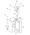
以下、図面を参照して、この発明の一実施形態について説明する。図1は、本実施形態に係る収納装置20を示した図であり、収納装置20は、ホトマスク(半導体装置製造用部材)40の収納・運搬ケース10と、エア供給装置21とから構成されている。
収納・運搬ケース10は、ホトマスク40を開口部11から収納可能とする容器本体112と、容器本体12の開口部11を閉塞する蓋体13とから構成されている。
この容器本体12は、矩形状の底壁部12aと、この底壁部12aの外周縁部に配置された側壁部12bと、前壁部12cと、後壁部12dとから構成されている。
容器本体12と蓋体13とは、図示しない緊締部材により堅固に連結可能とされており、容器本体12と蓋体13とが連結されると容器本体12内が密封状態とされる。
Hereinafter, an embodiment of the present invention will be described with reference to the drawings. FIG. 1 is a view showing a
The storage /
The container
The
容器本体12には、内部にエアを供給可能とするエア供給機構14が設けられ、蓋体13には、容器本体12内のエアを外部に排出する排出機構15が設けられている。
エア供給機構14は、容器本体12の内外間を連通させるエア管(第1のエア管)14aと、外部から容器本体12内へのエアの流通を許し、その逆方向への流通を阻止する図示されない逆止弁と、供給されるエアに含まれる塵埃等の異物をろ過するための図示されないフィルタとから構成されている。
蓋体13には、エア排出機構15が設けられており、このエア排出機構15は、容器本体12の内外間を連通させるエア管(第2のエア管)15aと、容器本体12内の圧力が排出圧力P3となると容器本体12内の圧力を外部に排出する図示されない逆止弁と、図示されないフィルタとから構成されている。
エア排出機構15に設けられた逆止弁は、容器本体12内の内圧P1が、外圧P0より僅かに高い排出圧力P3となると、容器本体12内のエアを外部に排出するように設定されている。
The
The
The
The check valve provided in the
エア供給装置21は、容器本体12内にエアを供給するポンプ23と、容器本体12内の内圧P1を測定する圧力センサ24と、圧力センサ24の出力に基づいてポンプ23の駆動を制御する制御部25と、ポンプ23とエア管14aとを連結するエア管28とから構成されている。
制御部25は、容器本体12内の内圧P1が、設定圧力P2より高いか否かを判断する機能を有しており、設定圧力P2は、排出圧力P3より高く設定されている。
このエア供給装置21は、収納・運搬ケース10に対して、着脱可能なように構成されている。
The
The
The
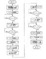
このように構成された収納装置20の収納・運搬ケース内10内にホトマスク40を収納、又は収納されたホトマスク40を取り出すには、収納・運搬ケース10にエア供給装置20が装着されて、図2に示されるフローチャートの手順に従って、容器本体12内の内圧P1が制御される。
すなわち、図1において、収納・運搬ケース10にエア供給機構21が装着されると、ポンプ23が容器本体12内にエアを供給し、エア供給機構14に設けられた逆止弁は、容器本体12に供給されたエアがエア管28の方向に逃げることを防止する。
In order to store the
That is, in FIG. 1, when the
この際、容器本体12内の内圧P1が排出圧力P3より低い場合には、制御部25は、エア供給機構21によるエアの供給を継続させると共に、エア排出機構15に設けられた逆止弁15aは、容器本体12内のエアを容器本体12内に維持する。このため、容器本体12内の内圧P1が漸次高くなる。
容器本体12内の内圧P1が排出圧力P3より高くなると、エア排出機構15の弁15aが容器本体12内のエアを排出する。
この際、エア排出機構15が容器本体12内からエアを排出する排出速度は、エア供給装置21が容器本体12内にエアを供給する供給速度より遅く設定されているため、容器本体12内の内圧P1は、漸次か高くなる。
エア排出機構15が、エアの排出を開始すると、圧力センサ24は、容器本体12内の内圧P1を測定する。
At this time, when the internal pressure P1 in the container
When the internal pressure P1 in the container
At this time, the discharge speed at which the
When the
制御部25は、測定された内圧P1が、設定圧力P2より高いか否かを判断し、内圧P1が設定圧力P2より小さい場合には、エア供給装置21のエア供給が維持される。
エア供給装置21のエア供給が維持されると、容器本体12内の内圧P1は、漸次高くなる。
そして、容器本体12内の内圧P1が設定圧力P2より高くなると、制御部25は、エア供給装置21のエア供給を停止させる。
この際、蓋体13が開放されると、容器本体12内の内圧P1は、外圧より高い設定圧力P2より高くされているため、容器本体12内のエアが外部に向けて噴出することとなる。このため、容器本体12内に異物が浸入することが防止され、容器本体12内に収納されたホトマスク40の表面に異物が付着することが防止される。
さらに、容器本体12内のエアが外部に噴出すると、容器本体12内の内圧P1が設定圧力P2より低くなり、制御部25がエア供給装置21のポンプ23を駆動して、容器本体12内にエアの供給を再開する。
The
When the air supply of the
And if the internal pressure P1 in the container
At this time, when the
Further, when the air in the
このため、蓋体13が開放された状態においては、容器本体12内からは、エアが常時噴出することとなり、収納されたホトマスク40を取り出したり、ホトマスク40を収納したりする際においても、容器本体12内に異物が浸入したり、ホトマスク40の表面に異物が付着することが防止される。
ホトマスク40の収納又は取出しが完了した後に、収納・運搬ケース10の蓋体13を閉めて、蓋体13と容器本体12とを緊締して、容器本体12内を密封する。
このように、蓋体13が閉じられると、容器本体12内の内圧P1は、上記と同様の手順により所定内圧P2とされる。
容器本体12内の内圧P1が所定内圧P2とされると、制御部25は、ポンプ23のエア供給を停止させ、エア供給装置21の駆動を停止させる。
エア供給機構21の駆動が停止されると、収納・運搬ケース10からエア供給機構21が取り外される。
For this reason, when the
After the storage or removal of the
Thus, when the
When the internal pressure P1 in the
When the driving of the
取り外された収納・運搬ケース10において、容器本体12内は、エア排出機構15に設けられた逆止弁により、内圧P1が排出圧力P3より高く維持される。
このため、エア供給装置21が取り外された収納・運搬ケース10がその後、蓋体13が開放されたとしても、容器本体12内の内圧P1は、外圧P0より高く維持されているため、容器本体12内からエアが噴出することとなり、外部の異物が容器本体12内に浸入することが防止され、ホトマスク40の表面に異物が付着することが防止される。
In the removed storage /
For this reason, even if the storage /
のように、本実施形態に係る収納装置20によれば、収納・運搬ケース10の蓋体13が開放された際には、容器本体13内からエアが常時噴出するため、ホトマスク40を収納又は、取り出す際においても、容器本体12内に異物が浸入し、ホトマスク40の表面に異物が付着することを確実に防止することができる。
また、収納・運搬ケース10がエア供給装置21から取り外された後、蓋体13が開放された場合においても、容器本体12内のエアが噴出するため、ホトマスク40に異物が付着することを防止することができる。
さらに、エア供給装置21と、収納・運搬ケース10とは、着脱可能とされているため、エア供給装置21は、収納・運搬ケース10の内圧P1を所定内圧P2とした後に、この収納・運搬ケース10から取り外され、他の収納・運搬ケース10にエアを供給することができるため、収納装置20には、少なくとも一つのエア供給装置21が設けられておればよく、収納装置20の構成を簡易なものとすることができる。
その上、エア供給機構21は、収納・運搬ケース10が装着された際においてのみ、エアを供給することとしているため、収納装置20本体の維持費用を低廉なものとすることができる。
As described above, according to the
Further, even when the
Further, since the
In addition, since the
なお、本実施形態においては、容器本体12内の内圧P1が所定内圧P2となると、圧力センサ24の出力に基づいて、制御部25がエア源23のエア供給を停止することとしているが、これに代えて、図1に示されるように、エア管28に外部に連通するバイパス管26と、収納・運搬ケース10方向又は外部へ選択的に導く切換弁26とを設けて、圧力センサ24の出力に応じて、エアを容器本体12内に供給したり、外部に排出したりすることにより、容器本体12内の内圧を所定内圧とすることとしてもよい。
すなわち、圧力センサ24が容器本体12内の内圧P1を測定し、容器本体12内の内圧P1が所定内圧P2より低い場合には、切換弁26はエア源23から供給されるエアを収納・運搬ケース10側に向けてエアを供給する。
そして、容器本体12内の内圧P1が所定内圧P2より高くなると、制御部25は、切換弁26aを切り換えて、エア源24から供給されるエアをバイパス管26方向に流通するように切り換えて、エアが外部に流出するようする。このため、容器本体12内の内圧P1は、所定内圧P2とすることができる。
In the present embodiment, when the internal pressure P1 in the
That is, when the
When the internal pressure P1 in the
また、容器本体12内の内圧P1が外圧P0より低いことにより、エア供給機構14に設けられた逆止弁14に容器本体12から圧力を受けていない場合には、蓋体13と容器本体12との緊締状態を保持する緊締保持機構を設けてもよい。
この場合、蓋体13が開放される際には、確実にエアが噴出することとなり、容器本体12内に異物が浸入することを確実に防止することができると共に、ホトマスク40の表面に異物が付着することを防止することができる。
また、本実施形態においては、エア供給機構14と、エア排出機構15とは、それぞれ、容器本体12及び蓋体13から突出するように設けられているが、収納・運搬ケース10内に埋め込まれてもよい。
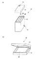
さらに、図3(a)に示されるように、収納・運搬ケース10は、容器本体12を深さ方向に長く構成してもよい。この場合、ホトマスク40は、容器本体12の深さ方向に直立するように配置され、深さ方向と直交する方向に沿って複数配置することができる。
その上、図3(b)に示されるように、蓋体13と、容器本体12とがピン等により連結された蝶番式に構成されてもよい。
また、本実施形態においては、半導体装置製造用部材として、ホトマスク40に適用した例を示したが、ホトマスク40に限られず、ウェーハを収納することとしてもよい。
Further, when the internal pressure P1 in the
In this case, when the
In the present embodiment, the
Further, as shown in FIG. 3A, the storage /
In addition, as shown in FIG. 3 (b), the
In this embodiment, an example in which the semiconductor device manufacturing member is applied to the
この発明に係る半導体装置製造用部材の収納・運搬ケース、収納装置及び、収納装置のエア供給制御方法によれば、収納された半導体装置製造部材の表面にエアを良好に流すことにより、半導体装置製造用部材の表面に塵埃が付着することを確実に防止でき、また、簡易な構成とすることができ、さらに、維持費用を低廉なものとすることができるため、産業上の利用可能性が認められる。 According to the housing / transport case for the semiconductor device manufacturing member, the storage device, and the air supply control method for the storage device according to the present invention, the semiconductor device can be obtained by allowing air to flow well over the surface of the stored semiconductor device manufacturing member. It is possible to reliably prevent the dust from adhering to the surface of the manufacturing member, to be able to have a simple configuration, and to reduce the maintenance cost. Is recognized.
10 収納運搬ケース
20 収納装置
21 エア供給装置
23 エア源
25 制御部
DESCRIPTION OF
Claims (6)
前記容器本体にはその内部にエアを供給可能とするエア供給機構が設けられ、
前記蓋体には前記容器本体内部のエアを排出可能とするエア排出機構が設けられていることを特徴とする半導体装置製造用部材の収納・運搬ケース。 A container main body capable of storing the semiconductor device manufacturing member from the opening, and a lid for closing the opening of the container main body,
The container body is provided with an air supply mechanism capable of supplying air therein,
A housing / carrying case for a semiconductor device manufacturing member, wherein the lid is provided with an air discharge mechanism capable of discharging air inside the container body.
前記エア供給機構は、前記容器本体に設けられ、該容器本体の内外間を連通させる第1のエア流路と、該第1のエア流路に設けられ、外部から該容器本体へエアの流通を許し、その逆方向への流通を阻止する第1の逆止弁とを備えてなり、
前記エア排出機構は、前記蓋体に設けられ、該容器本体の内外間を連通させる第2のエア流路と、該第2の流路に設けられ、該容器本体内の圧力が一定値以上になったときに該容器本体内のエアを外部に排出する第2の逆止弁とを備えてなることを特徴とする半導体装置製造用部材の収納・運搬ケース。 In the storage / transport case of the semiconductor device manufacturing member according to claim 1,
The air supply mechanism is provided in the container main body, and is provided in the first air flow path that communicates between the inside and the outside of the container main body, and is provided in the first air flow path, and air flows from the outside to the container main body. And a first check valve that prevents flow in the opposite direction,
The air discharge mechanism is provided in the lid, and is provided in the second air flow path communicating between the inside and the outside of the container main body, and in the second flow path, and the pressure in the container main body is a predetermined value or more. And a second check valve that discharges the air in the container body to the outside when the container is stored.
該半導体装置製造用部材の収納・運搬ケースの前記エア供給機構に接続されて前記容器本体内にエアを供給するエア供給装置を備えてなり、
前記エア供給装置は、該容器本体内にエアを供給するポンプと、該容器本体内の圧力を検出するセンサと、該センサの出力にも基づいて前記ポンプの駆動を制御する制御部とを備えてなることを特徴とする半導体装置製造用部材の収納装置。 A housing and carrying case for a semiconductor device manufacturing member according to claim 1 or 2,
An air supply device connected to the air supply mechanism of the housing and carrying case of the semiconductor device manufacturing member to supply air into the container body;
The air supply device includes a pump that supplies air into the container body, a sensor that detects a pressure in the container body, and a control unit that controls driving of the pump based on an output of the sensor. A member storage device for manufacturing a semiconductor device.
前記ポンプにより供給されるエアを前記半導体装置製造用部材の収納・運搬ケース方向又は外部へ選択的に導く切換弁を備え、前記センサの出力に基づいて前記出力に基づいて前記センサの出力に基づいて前記ポンプの駆動の制御に代えて前記切換弁を制御するように構成されていることを特徴とする半導体装置製造用部材の収納装置。 In the storage device for a semiconductor device manufacturing member according to claim 3,
A switching valve that selectively guides the air supplied by the pump to the housing / transport case of the semiconductor device manufacturing member or to the outside, and based on the output based on the output from the sensor A device for storing a member for manufacturing a semiconductor device, wherein the switching valve is controlled instead of controlling the driving of the pump.
前記半導体装置製造用部材の収納・運搬ケースに対し、前記エア供給装置が着脱自在に接続されるように構成されていることを特徴とする半導体装置製造用部材の収納装置。 In the storage device for a semiconductor device manufacturing member according to claim 3 or 4,
An apparatus for housing a semiconductor device manufacturing member, wherein the air supply device is detachably connected to a housing / transport case for the semiconductor device manufacturing member.
前記半導体装置製造用部材の収納・運搬ケースに前記収納装置を装着し、前記ポンプを起動して前記容器本体内にエアを供給し、前記容器本体内の内圧が、設定圧力より低く且つ、排出圧力より高くなったときに、前記排出機構が前記容器本体内のエアを排出し、前記容器本体内の内圧が設定圧力より高くなったときに、前記エア供給装置の駆動が停止されることを特徴とする収納装置のエア供給制御方法。
An air supply control method for a storage device according to any one of claims 3 to 5,
The housing device is mounted on the housing / transport case of the semiconductor device manufacturing member, the pump is activated to supply air into the container body, and the internal pressure in the container body is lower than a set pressure and is discharged. When the pressure becomes higher than the pressure, the discharge mechanism discharges the air in the container body, and when the internal pressure in the container body becomes higher than a set pressure, the driving of the air supply device is stopped. An air supply control method for a storage device.
Priority Applications (1)
| Application Number | Priority Date | Filing Date | Title |
|---|---|---|---|
| JP2004107895A JP2005292494A (en) | 2004-03-31 | 2004-03-31 | Housing/carrying case for semiconductor device producing member, housing apparatus, and air supply control method for housing apparatus |
Applications Claiming Priority (1)
| Application Number | Priority Date | Filing Date | Title |
|---|---|---|---|
| JP2004107895A JP2005292494A (en) | 2004-03-31 | 2004-03-31 | Housing/carrying case for semiconductor device producing member, housing apparatus, and air supply control method for housing apparatus |
Publications (1)
| Publication Number | Publication Date |
|---|---|
| JP2005292494A true JP2005292494A (en) | 2005-10-20 |
Family
ID=35325476
Family Applications (1)
| Application Number | Title | Priority Date | Filing Date |
|---|---|---|---|
| JP2004107895A Pending JP2005292494A (en) | 2004-03-31 | 2004-03-31 | Housing/carrying case for semiconductor device producing member, housing apparatus, and air supply control method for housing apparatus |
Country Status (1)
| Country | Link |
|---|---|
| JP (1) | JP2005292494A (en) |
Cited By (3)
| Publication number | Priority date | Publication date | Assignee | Title |
|---|---|---|---|---|
| JP2007199706A (en) * | 2006-01-25 | 2007-08-09 | Internatl Business Mach Corp <Ibm> | System and method for storing and transporting photomasks in fluid |
| CN100495679C (en) * | 2006-03-29 | 2009-06-03 | 联华电子股份有限公司 | Wafer transport box and operation method thereof |
| CN109932866A (en) * | 2017-12-15 | 2019-06-25 | 台湾积体电路制造股份有限公司 | Photomask carrier box and method for carrying and cleaning photomask device |
-
2004
- 2004-03-31 JP JP2004107895A patent/JP2005292494A/en active Pending
Cited By (3)
| Publication number | Priority date | Publication date | Assignee | Title |
|---|---|---|---|---|
| JP2007199706A (en) * | 2006-01-25 | 2007-08-09 | Internatl Business Mach Corp <Ibm> | System and method for storing and transporting photomasks in fluid |
| CN100495679C (en) * | 2006-03-29 | 2009-06-03 | 联华电子股份有限公司 | Wafer transport box and operation method thereof |
| CN109932866A (en) * | 2017-12-15 | 2019-06-25 | 台湾积体电路制造股份有限公司 | Photomask carrier box and method for carrying and cleaning photomask device |
Similar Documents
| Publication | Publication Date | Title |
|---|---|---|
| EP2055185B1 (en) | Overflow device for water tank | |
| KR102087485B1 (en) | A Water Purifier For A Pet | |
| KR100386096B1 (en) | Powder container,powder discharging apparatus and image forming apparatus | |
| TWI385749B (en) | Stored item transport system | |
| KR101750647B1 (en) | Liquid supply device and substrate processing device | |
| EP1106363A3 (en) | Recording liquid feed path and container, recording liquid feeding device having the same, as well as, surface modifying method for this device | |
| WO2006052005A3 (en) | Developer supply container and image forming apparatus | |
| JP5047916B2 (en) | Ink supply device for ink jet printer and reverse flow blocking device | |
| SG143277A1 (en) | Ink cartiridge attachment/detachment device, recording apparatus, liquid ejection apparatus, and liquid container | |
| TW201907467A (en) | Blade mounting and dismounting jig, blade mounting and dismounting method, blade extracting method, and cutting apparatus | |
| US8132533B2 (en) | Overflow device for water tank | |
| JP2005292494A (en) | Housing/carrying case for semiconductor device producing member, housing apparatus, and air supply control method for housing apparatus | |
| US20050286936A1 (en) | Toner cartridge | |
| WO2008039627A3 (en) | Dust controlled container filling system | |
| US7349656B2 (en) | Volume reducing apparatus and toner supplying apparatus used in image forming device | |
| KR101659679B1 (en) | Ink Supply for an Ink Printer | |
| JP4320724B2 (en) | Processing waste liquid recovery device, recovery control method thereof, and developing device to which processing waste liquid recovery device is applied | |
| KR101660427B1 (en) | Continuous Toner Powder Supply System for Laser Printers and Copiers | |
| JP2001337526A (en) | Toner supply container | |
| KR100509431B1 (en) | A supply device for photo resist and its supply method | |
| TWI390597B (en) | Photoresist supply device | |
| JP2007189925A (en) | Live fish storage container and air pump device storage method in live fish storage container | |
| JP2008290250A (en) | Raw material feeder for injection molding machine | |
| JP4334998B2 (en) | Processing liquid replenishing apparatus and processing liquid replenishing method for photosensitive lithographic printing plate processing apparatus | |
| JP2002200617A (en) | Subtank for resin dryer |