JP2005292452A - Image observing device and adjusting method of image observing position - Google Patents
Image observing device and adjusting method of image observing position Download PDFInfo
- Publication number
- JP2005292452A JP2005292452A JP2004107250A JP2004107250A JP2005292452A JP 2005292452 A JP2005292452 A JP 2005292452A JP 2004107250 A JP2004107250 A JP 2004107250A JP 2004107250 A JP2004107250 A JP 2004107250A JP 2005292452 A JP2005292452 A JP 2005292452A
- Authority
- JP
- Japan
- Prior art keywords
- image
- display panel
- observer
- unit
- display
- Prior art date
- Legal status (The legal status is an assumption and is not a legal conclusion. Google has not performed a legal analysis and makes no representation as to the accuracy of the status listed.)
- Pending
Links
- 238000000034 method Methods 0.000 title abstract description 9
- 238000001514 detection method Methods 0.000 claims abstract description 62
- 230000008859 change Effects 0.000 claims abstract description 14
- 210000001747 pupil Anatomy 0.000 claims description 46
- 230000003287 optical effect Effects 0.000 claims description 26
- 238000007689 inspection Methods 0.000 claims description 11
- 210000001525 retina Anatomy 0.000 claims description 6
- NJPPVKZQTLUDBO-UHFFFAOYSA-N novaluron Chemical group C1=C(Cl)C(OC(F)(F)C(OC(F)(F)F)F)=CC=C1NC(=O)NC(=O)C1=C(F)C=CC=C1F NJPPVKZQTLUDBO-UHFFFAOYSA-N 0.000 claims description 3
- 238000003384 imaging method Methods 0.000 description 23
- 238000001356 surgical procedure Methods 0.000 description 14
- 210000003128 head Anatomy 0.000 description 12
- 238000001444 catalytic combustion detection Methods 0.000 description 11
- 238000010586 diagram Methods 0.000 description 7
- 230000000694 effects Effects 0.000 description 4
- 230000008569 process Effects 0.000 description 4
- 230000007246 mechanism Effects 0.000 description 3
- 230000000399 orthopedic effect Effects 0.000 description 3
- 238000009792 diffusion process Methods 0.000 description 2
- 230000009467 reduction Effects 0.000 description 2
- 102100022361 CAAX prenyl protease 1 homolog Human genes 0.000 description 1
- 0 CCC1CCC*=C(*C*CCCC=CC)CCCC(CC2)[C@@](C)CC2CCCC1 Chemical compound CCC1CCC*=C(*C*CCCC=CC)CCCC(CC2)[C@@](C)CC2CCCC1 0.000 description 1
- 101000824531 Homo sapiens CAAX prenyl protease 1 homolog Proteins 0.000 description 1
- 101001003584 Homo sapiens Prelamin-A/C Proteins 0.000 description 1
- 125000002066 L-histidyl group Chemical group [H]N1C([H])=NC(C([H])([H])[C@](C(=O)[*])([H])N([H])[H])=C1[H] 0.000 description 1
- 101100123587 Saccharomyces cerevisiae (strain ATCC 204508 / S288c) HDA3 gene Proteins 0.000 description 1
- 101100297842 Schizosaccharomyces pombe (strain 972 / ATCC 24843) plo1 gene Proteins 0.000 description 1
- 230000009471 action Effects 0.000 description 1
- 230000015572 biosynthetic process Effects 0.000 description 1
- 239000004973 liquid crystal related substance Substances 0.000 description 1
- 230000004048 modification Effects 0.000 description 1
- 238000012986 modification Methods 0.000 description 1
Images


Landscapes
- Microscoopes, Condenser (AREA)
Abstract
Description
本発明は、特に脳神経外科、眼科、整形外科等で使用される術部の拡大観察画像を表示する画像観察装置と画像観察位置の調整方法に関する。 The present invention relates to an image observation apparatus for displaying a magnified observation image of an operation part used in neurosurgery, ophthalmology, orthopedic surgery, and the like, and an image observation position adjusting method.
一般に、脳神経外科、眼科、整形外科等では、術者が処置を行う術部は微細な部分である。そのため、術者が術部の処置を行う際に微細な術部の拡大3次元画像を得るために手術用顕微鏡が使用される。一般的な手術用顕微鏡は左右独立した観察光路と、それに対する左右一対の接眼レンズを有し、各々の接眼レンズを左右眼で視察することにより、術部を拡大、かつ立体観察ができる、いわゆる実体顕微鏡を構成している。 Generally, in neurosurgery, ophthalmology, orthopedic surgery, etc., the surgical site where the surgeon performs treatment is a fine part. Therefore, a surgical microscope is used to obtain a fine enlarged three-dimensional image of the surgical site when the surgeon performs a surgical procedure. A general surgical microscope has a left and right independent observation optical path, and a pair of left and right eyepieces. By observing each eyepiece with the left and right eyes, the operation part can be enlarged and stereoscopic observation can be performed. It constitutes a stereomicroscope.
このような、手術用顕微鏡で術部の拡大立体観察を行う場合、術者は手術用顕微鏡の接眼レンズを覗き込むといった動作を強いられるため、観察位置や観察姿勢の制限を受ける。その制限を緩和し、自由な位置、姿勢での観察を可能にするために術部の画像を一且CCD等の撮像素子で電子画像化し、それをモニターなどの表示手段で表示するいわゆる電子画像顕微鏡がある。その一例として、特許文献1や、特許文献2のような手術用顕微鏡がある。
When performing an enlarged stereoscopic observation of the surgical part with such a surgical microscope, the surgeon is forced to look into the eyepiece of the surgical microscope, and thus is restricted in the observation position and the observation posture. A so-called electronic image in which the image of the surgical site is converted into an electronic image with an image pickup device such as a CCD and displayed on a display means such as a monitor in order to relax the restriction and enable observation at a free position and posture. There is a microscope. As an example, there are surgical microscopes such as
例えば、特許文献1では、手術用顕微鏡の鏡体部に表示パネル(液晶モニタ(LCD))を取り付けている。顕微鏡鏡体部内にはその左右観察光路上の各々の結像点にそれぞれ撮像素子(以下CCD)が配置されている。そして、顕微鏡鏡体部に内蔵されている左右一対のCCDで術部の観察像を一且電子画像として撮像する。その後、左右一対のCCDによって得られた電子画像を顕微鏡鏡体部の表示パネルに表示するようになっている。この場合には術者は表示パネルの表示画像を目視することにより、手術用顕微鏡の観察像を観察することができる。これにより、術者は顕微鏡本体に設けられた小さな接眼レンズを覗き込む必要がなく、比較的楽な姿勢で術部の拡大観察が可能となる。
For example, in
また、特許文献2には、手術用顕微鏡の顕微鏡本体から切り離した独立したファインダーや、HMD(ヘッド・マウント・ディスプレイ)を設けた構成が示されている。ここでは、手術用顕微鏡の顕微鏡本体内に特許文献1と同様に左右一対のCCDを内蔵し、得られた電子画像を独立したファインダーや、HMDで表示するようになっている。これにより、術者が術部に対して自由に移動しても、常に術部の拡大3次元画像を観察できる。そのため、術者はさらに自由な位置、姿勢で、術部の拡大3次元観察が可能になると共に、顕微鏡の配置位置も自由度が広がるため、広い術作業空間が確保できる。
特許文献1の装置では、顕微鏡本体の表示パネルは、特定の取り付け位置で固定されている。この表示パネルは、正面から表示画像を見る場合には明瞭に観察できるが、正面から外れた斜め方向から表示パネルを見た場合には表示画像が見難くなる。そのため、術者が表示パネルの鮮明な表示画像を見ることができる方向は比較的狭い範囲に制限されている。その結果、手術の開始時に術者が表示パネルの鮮明な表示画像を見ることができる方向に顕微鏡本体の表示パネルを配置していたとしても、手術中に術者が術部に対して移動した場合には表示パネルの表示画像が見難くなる。
In the apparatus of
また、特許文献2の装置では、顕微鏡本体から切り離した独立したファインダーを設けた場合には術者の観察姿勢に応じて、接眼レンズを保持しているアームを配置し、さらに接眼レンズを覗き込むといった作業が必要となる。そのため、術者は術部の拡大観察時には、常に顔を接眼レンズに対して顔を固定しておくことが必要となるので、手術中に術者が術部に対して移動した場合には術部の拡大観察が不能になる。
Moreover, in the apparatus of
また、HMDを使用する場合には術者の頭部にHMDのような重量物が装着されるので、手術時の術者の疲労が大きくなる。そして、HMDの装着時には、HMDの表示部を目の前にセットすることにより、HMDの表示画像を目視する拡大観察が行なわれる。また、直視観察を行なう場合には目の前にセットされているHMDの表示部を目の前から外れた場所に移動させる切り替え作業が必要になる。そして、手術中は、処置の進行に応じてHMDの表示画像を目視する拡大観察と、HMDの表示部から目を離して術部を直視する直視観察とを必要に応じて使い分ける必要がある。そのため、術者は手術中に術部の直視と拡大観察とを切り替える作業を比較的頻繁に行なう必要があるので、その作業が面倒であり、手術全体の作業効率が低下するおそれがある。 In addition, when an HMD is used, since a heavy object such as an HMD is attached to the operator's head, the operator's fatigue during surgery increases. Then, when the HMD is mounted, the HMD display unit is set in front of the user's eyes, so that enlarged observation for visually observing the display image of the HMD is performed. In addition, when performing direct-view observation, it is necessary to perform a switching operation of moving the display unit of the HMD set in front of the eyes to a place off the eyes. During surgery, it is necessary to properly use magnified observation in which a display image of the HMD is visually observed as the treatment progresses, and direct observation in which the surgical part is directly viewed while keeping an eye on the display part of the HMD. Therefore, the surgeon needs to perform the operation of switching between direct viewing and magnified observation of the surgical site relatively frequently during the operation, so that the operation is troublesome and there is a possibility that the operation efficiency of the entire operation is reduced.
本発明は上記事情に着目してなされたもので、その目的は、術者が自由に姿勢変更しても、常に、術部の拡大画像観察が可能であるうえ、手術中の術者の疲労軽減することができ、手術全体の作業効率の向上を図ることができる画像観察装置と画像観察位置の調整方法を提供することにある。 The present invention has been made paying attention to the above circumstances, and the purpose of the present invention is to always allow an enlarged image of the surgical site to be observed even if the operator freely changes the posture, and to reduce fatigue of the operator during the operation. An object of the present invention is to provide an image observation apparatus and an image observation position adjustment method that can be reduced and can improve the work efficiency of the entire operation.
請求項1の発明は、術部の観察画像を表示する表示手段と、前記表示手段を3次元的に移動可能に支持する表示手段支持部と、前記表示手段を自由な位置に配置した状態で係脱可能に固定する固定部とを有する架台部と、前記表示手段に対する観察者の位置を検出する位置検出手段と、前記位置検出手段による検出結果に応じて、前記架台部を動かして前記表示手段の位置を変更する位置変更手段とを具備することを特徴とする画像観察装置である。
そして、本請求項1の発明では、架台部の表示手段支持部によって表示手段を3次元的に移動可能に支持させる。術部の観察時には表示手段を自由な位置に配置した状態で固定部によって固定する。この状態で、表示手段に対する観察者の位置を位置検出手段によって検出する。この位置検出手段による検出結果に応じて、位置変更手段によって架台部を動かして表示手段の位置を変更することにより、観察画像を表示する表示手段を、手術の進行に対応して適切な位置に配置させるようにしたものである。これにより、FMDのような重量物を頭部につけることなく、術者は術部に対する頭の位置を変更しても、画像表示手段の位置を変更することなく、常に、術部立体拡大観察画像を観察でき、疲労軽減、手術効率の向上につながる。
According to the first aspect of the present invention, the display means for displaying the observation image of the surgical site, the display means support section for supporting the display means so as to be movable in three dimensions, and the display means are arranged at free positions. A display unit having a fixing unit that is detachably fixed, a position detection unit that detects a position of an observer with respect to the display unit, and the display unit by moving the mount unit according to a detection result by the position detection unit. An image observation apparatus comprising: a position changing unit that changes the position of the unit.
In the first aspect of the present invention, the display means is supported so as to be movable three-dimensionally by the display means support portion of the gantry. When observing the surgical site, the display means is fixed at the free position and fixed by the fixing portion. In this state, the position of the observer with respect to the display means is detected by the position detection means. By changing the position of the display means by moving the gantry by the position change means according to the detection result by the position detection means, the display means for displaying the observation image is set to an appropriate position corresponding to the progress of the operation. It is intended to be arranged. Thereby, without attaching a heavy object such as FMD to the head, even if the operator changes the position of the head with respect to the operation part, the operation part stereoscopic observation is always performed without changing the position of the image display means. Images can be observed, reducing fatigue and improving surgical efficiency.
請求項2の発明は、前記位置変更手段は、前記表示手段と、前記表示手段に表示される画像を観察する観察者の相対位置関係を一定に保つ相対位置固定手段を有することを特徴とする請求項lに記載の画像観察装置である。
そして、本請求項2の発明では、術部の画像を表示する表示手段と、それを観察する観察者との相対位置関係を位置変更手段の相対位置固定手段によって常に一定に保つようにしたものである。
The invention according to
In the invention of
請求項3の発明は、前記位置検出手段は、前記観察者の眼の方向に向けて検査光を照射する光照射部と、前記光照射部からの検査光が前記観察者の眼の網膜で反射された反射光を検出する瞳検出部とを具備し、前記相対位置固定手段は、前記瞳検出部の検出結果に基いて前記観察者の位置変化に応じて前記観察者との相対位置関係を一定に保つ状態で前記位置変更手段を駆動する駆動手段を具備することを特徴とする請求項2に記載の画像観察装置である。
そして、本請求項3の発明では、位置検出手段の光照射部によって観察者の眼の方向に向けて検査光を照射し、光照射部からの検査光が観察者の眼の網膜で反射された反射光を瞳検出部によって検出する。このとき、相対位置固定手段の駆動手段によって瞳検出部の検出結果に基いて観察者の位置変化に応じて観察者との相対位置関係を一定に保つ状態で位置変更手段を駆動するようにしたものである。
According to a third aspect of the present invention, the position detection unit includes a light irradiation unit that irradiates inspection light toward the observer's eyes, and the inspection light from the light irradiation unit is in the retina of the observer's eyes. A pupil detection unit for detecting reflected reflected light, wherein the relative position fixing means is based on a detection result of the pupil detection unit and a relative positional relationship with the observer according to a change in the position of the observer. The image observation apparatus according to
In the third aspect of the invention, the light irradiation unit of the position detection unit irradiates the inspection light toward the observer's eyes, and the inspection light from the light irradiation unit is reflected by the retina of the observer's eyes. The reflected light is detected by the pupil detection unit. At this time, the position changing means is driven by the driving means of the relative position fixing means while keeping the relative positional relationship with the observer constant according to the position change of the observer based on the detection result of the pupil detection unit. Is.
請求項4の発明は、前記位置検出手段は、前記観察者に装着される第1の発光手段と、前記表示手段に装着される第2の発光手段と、前記第1の発光手段の光像および前記第2の発光手段の光像を検出するの光像検出手段とを具備するナビゲーション装置を備えていることを特徴とする請求項1に記載の画像観察装置である。
According to a fourth aspect of the present invention, the position detecting means includes a first light emitting means attached to the observer, a second light emitting means attached to the display means, and an optical image of the first light emitting means. The image observation apparatus according to
そして、本請求項4の発明では、位置検出手段のナビゲーション装置の動作時には観察者に装着される第1の発光手段の光像および表示手段に装着される第2の発光手段の光像を光像検出手段によって検出し、表示手段に対する観察者の位置を検出するようにしたものである。 According to the fourth aspect of the present invention, when the navigation device of the position detecting means operates, the light image of the first light emitting means attached to the observer and the light image of the second light emitting means attached to the display means are optically transmitted. The position of the observer with respect to the display means is detected by the image detection means.
請求項5の発明は、術部の観察画像を表示する表示手段を表示手段支持部によって3次元的に移動させて任意の初期位置にセットする初期セット工程と、前記表示手段に対する観察者の位置を検出する位置検出工程と、前記位置検出工程による検出結果に応じて、前記表示手段支持部を動かして前記表示手段の位置を変更する位置変更工程とを具備することを特徴とする画像観察位置の調整方法である。 The invention according to claim 5 is an initial setting step in which the display means for displaying the observation image of the surgical site is three-dimensionally moved by the display means support portion and set at an arbitrary initial position, and the position of the observer with respect to the display means An image observation position comprising: a position detection step for detecting the position of the display means; and a position change step for changing the position of the display means by moving the display means support portion in accordance with a detection result of the position detection process. This is the adjustment method.
そして、本請求項5の発明では、術部の観察画像を表示する表示手段を表示手段支持部によって3次元的に移動させて任意の初期位置にセットした(初期セット工程)のち、表示手段に対する観察者の位置を検出する(位置検出工程)。続いて、この位置検出工程による検出結果に応じて、表示手段支持部を動かして表示手段の位置を変更する(位置変更工程)ことにより、画像観察位置を調整するようにしたものである。 In the invention of claim 5, after the display means for displaying the observation image of the surgical site is moved three-dimensionally by the display means support part and set at an arbitrary initial position (initial setting step), The position of the observer is detected (position detection process). Subsequently, the image observation position is adjusted by moving the display means support portion and changing the position of the display means (position change process) according to the detection result of the position detection process.
本発明によれば、術者が自由に姿勢変更しても、常に、術部の拡大画像観察が可能であるうえ、手術中の術者の疲労軽減することができ、手術全体の作業効率の向上を図ることができる。 According to the present invention, even if the surgeon freely changes his / her posture, it is possible to always observe an enlarged image of the surgical part, and to reduce the fatigue of the surgeon during the operation, and to improve the work efficiency of the entire operation. Improvements can be made.
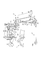
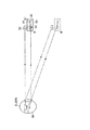
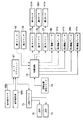
以下、本発明の第1の実施の形態を図1乃至図9を参照して説明する。図1は手術時に患者の術部Pの拡大観察画像を表示する本実施の形態の画像観察装置を示すものである。図1中で、参照符号1は術部Pの観察画像を撮像する撮像装置である。この撮像装置1には撮像カメラ2と、この撮像カメラ2を自由に移動調整可能に支持する支持装置、例えば多関節アーム3とが設けられている。撮像カメラ2には術部Pの観察像を電子画像として拡大3次元画像を撮像する左右一対のCCD44L,44R(図3参照)を備えた観察光学系が内蔵されている。
The first embodiment of the present invention will be described below with reference to FIGS. FIG. 1 shows an image observation apparatus of the present embodiment that displays an enlarged observation image of a patient's surgical part P during surgery. In FIG. 1,
また、術部Pの近傍位置には撮像装置1とは異なる場所に術部Pの観察画像を表示する表示パネル(表示手段)4が配設されている。この表示パネル4は、例えばフレネル凹面鏡パネルで構成され、支持架台(架台部)5によって3次元的に移動可能に支持されている。
In addition, a display panel (display unit) 4 that displays an observation image of the surgical site P at a location different from the
支持架台5には、架台ベース6と、この架台ベース6上に上向に突設された支柱7と、この支柱7の上端部に取付けられた操作アーム(表示手段支持部)8とが設けられている。支柱7は、軸受部9を介して、架台ベース6に対して鉛直方向の軸O1回りに回動可能に取り付けられる。この軸受部9には、第1電磁ブレーキ(固定部)9bが内蔵されている。そして、この第1電磁ブレーキ9bによって支柱7が回転停止状態で固定されるようになっている。
The support frame 5 is provided with a
操作アーム8には、3つ(第1,第2,第3の)の平行四辺形リンク10,11,12が設けられている。第1の平行四辺形リンク10には、2つの横アーム13,14と、2つの縦アーム15,16とが設けられている。2つの横アーム13,14は水平方向に向けて上下に平行に配置されている。2つの縦アーム15,16は2つの横アーム13,14間に左右に平行に配置されている。これら4つのアーム13〜16は4つの軸受部17〜20を介してそれぞれ回動自在に連結されて第1の平行四辺形リンク10が構成されている。
The
縦アーム15の略中間部には、軸受部21が設けられている。この軸受部21は、支柱7に対して、水平方向の軸O2回りに回動可能に支持される。この軸受部21には、第2電磁ブレーキ(固定部)21bが内蔵されている。そして、第2電磁ブレーキ21bによって縦アーム15が支柱7に対して回転停止状態で固定されるようになっている。さらに、横アーム14の終端には、カウンターウエイト22が設けられる。このカウンターウエイト22によって軸O2回りの重量物の重量を相殺するようになっている。
A bearing
第2の平行四辺形リンク11には、2つの横アーム23,24と、2つの縦アーム25,26とが設けられている。2つの横アーム23,24は水平方向に向けて上下に平行に配置されている。2つの縦アーム25,26は2つの横アーム23,24間に左右に平行に配置されている。これら4つのアーム23〜26は4つの軸受部27〜30を介してそれぞれ回動自在に連結されて第2の平行四辺形リンク11が構成されている。
The
さらに、横アーム24には、横アーム13の一端が軸受部31を介して水平方向の中心軸O3回りに回動自在に取り付けられる。この軸受部31には、第3電磁ブレーキ(固定部)31bと第1モータ31mとが内蔵されている。そして、第1モータ31mによって横アーム24が横アーム13に対して軸O3回りに回動駆動され、第3電磁ブレーキ31bによって回転停止状態で固定されるようになっている。さらに、縦アーム25の下端部には、カウンターウエイト32が設けられる。このカウンターウエイト32によって軸O3回りの重量物(表示パネル4および第2,第3の平行四辺形リンク11,12などの重量)の重量を相殺するようになっている。
Furthermore, one end of the
第3の平行四辺形リンク12には、2つの横アーム33,34と、2つの縦アーム35,36とが設けられている。2つの横アーム33,34は水平方向に向けて上下に平行に配置されている。2つの縦アーム35,36は2つの横アーム33,34間に左右に平行に配置されている。これら4つのアーム33〜36は4つの軸受部37〜40を介してそれぞれ回動自在に連結されて第3の平行四辺形リンク12が構成されている。ここで、下側の横アーム34は、第2の平行四辺形リンク11の上側の横アーム23と一体化された共通の単一アームによって形成されている。同様に、図1中で右側の縦アーム36は、第2の平行四辺形リンク11の左側の縦アーム25と一体化された共通の単一アームによって形成されている。さらに、第3の平行四辺形リンク12の軸受部40は、第2の平行四辺形リンク11の軸受部27と共通の軸受部によって形成されている。
The
また、軸受部38には、第4電磁ブレーキ(固定部)38bと第2モータ38mとが内蔵されている。そして、第2モータ38mによって上側の横アーム33が縦アーム36に対して水平方向の軸O4回りに回動駆動され、第4電磁ブレーキ38bによって回転停止状態で固定されるようになっている。
The bearing
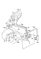
さらに、第3の平行四辺形リンク12の図1中で左側の縦アーム35の下端部には軸受部41を介して表示パネル支持アーム42が取り付けられる。軸受部41には、第5電磁ブレーキ(固定部)41bと第3モータ41mとが内蔵されている。そして、第3モータ41mによって表示パネル支持アーム42が縦アーム35に対して中心軸O5回りに回動駆動され、第5電磁ブレーキ41bによって回転停止状態で固定されるようになっている。
Further, a display
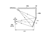
表示パネル支持アーム42は、図2に示すようにL字状に屈曲され、横アーム42aと縦アーム42bとを有するL字状アームによって形成されている。そして、表示パネル支持アーム42の横アーム42aが縦アーム35の下端部に取り付けられている。
As shown in FIG. 2, the display
表示パネル支持アーム42の縦アーム42bの下端部にはパネルホルダ42cが固定されている。このパネルホルダ42cには、表示パネル4が取付けられている。さらに、表示パネル支持アーム42の横アーム42aには、画像投影手段を構成する左右一対のプロジェクター43L、43Rが取付けられている。
A
また、縦アーム42bには略L字状のグリップアーム42dの一端部が連結されている。このグリップアーム42dの他端部には表示パネル4の横方向に配置されるグリップ部42eが連結されている。このグリップ部42eには2つの操作ボタン42f、42gが上下に並設されている。上側の操作ボタン42fは後述する第1のスイッチ48、下側の操作ボタン42gは後述する初期位置設定スイッチ58をそれぞれオンオフ操作するものである。
Further, one end of a substantially L-shaped
また、図3に示すように撮像カメラ2に内蔵された左右一対のCCD44L,44Rは、カメラコントローラ45に内蔵された左右一対のCCU(カメラコントロールユニット)45L,45Rにそれぞれ接続されている。さらに、左用のCCU45Lからの出力信号は左用のプロジェクター43Lに、右用のCCU45Rのからの出力信号は右用のプロジェクター43Rにそれぞれ入力される。
Also, as shown in FIG. 3, the pair of left and
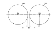
また、図2に示すように左右のプロジェクター43L、43Rは、それぞれの射出光軸PLおよびPRが表示パネル4上の中心軸O3と交わる点S上で一致するように、所定の角度αを有して取り付け配置される。これにより、プロジェクター43L、43Rから光軸PL,PRで表示パネル4に観察像が投影されると、左右の観察像が一致して表示パネル4上に投影される。また、図示しない左プロジェクター43Lが内蔵する投影光学系の射出瞳と、同じく図示しない右プロジェクター43Rが内蔵する投影光学系の射出瞳は表示パネル4のフレネル凹面鏡のレンズ作用と、拡散板の光拡散作用により、図5に示すように表示パネル4上のS点から所定の距離LS1の位置P1近傍に拡大された状態で投影され、前記左右の投影光学系の射出瞳は図6のOPL、OPRのごとく左右に分離された状態でそれぞれ所定の深度d1で形成される。左右の瞳OPL、OPRは、深度d1が30mm程度、中心点OL、ORからの半径r1が30mm程度、左右の瞳OPL、OPR間の距離d2が5mm程度にそれぞれ設定されている。これにより瞳OPL、OPR内に観察者(術者)Dの左右の眼EL、ERを一致させることにより、表示パネル4を見ている観察者(術者)Dの左眼ELには、入射光軸WLで観察像が導かれ、右眼ERには入射光軸WRで観察像が導かれる。その結果、プロジェクター43L、43Rから表示パネル4に投影される観察像が観察者Dによって3D(立体)観察される。
Further, as shown in FIG. 2, the left and
図4は、支持架台5の操作アーム8の動作を制御する、例えばワークステーションなどの制御部46の接続状態を示す。この制御部46には、第1電磁ブレーキ9b、第2電磁ブレーキ21b、第3電磁ブレーキ31b、第4電磁ブレーキ38b、第5電磁ブレーキ41b、第1モータ31m、第2モータ38m、第3モータ41mがそれぞれ接続されているとともに、支持架台5の操作用の第1のスイッチ48が接続されている。
FIG. 4 shows a connection state of a
第1のスイッチ48は、第1電磁ブレーキ9b、第2電磁ブレーキ21b、第3電磁ブレーキ31b、第4電磁ブレーキ38b、第5電磁ブレーキ41bをオンオフ操作するものである。第1のスイッチ48のオン操作時には上記各電磁ブレーキ9b,21b,31b,38b,41bによる操作アーム8の各軸受部9,21,31,38,41のロックが解除され、操作アーム8が3次元的に自由に移動可能に切替え操作される。さらに、第1のスイッチ48のオフ操作時には上記各電磁ブレーキ9b,21b,31b,38b,41bによって操作アーム8の各軸受部9,21,31,38,41がロックされ、操作アーム8が固定状態に切替え操作される。
The
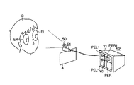
また、表示パネル4の上端部には、パネルホルダ42cに表示パネル4に対する観察者(術者)Dの位置を検出する位置検出手段49が設けられている。この位置検出手段49には、赤外線光源(光照射部)50と、赤外線カメラ51と、瞳検出部52とが設けられている。
Further, at the upper end portion of the
赤外線光源50は、観察者Dの眼ER、ELの方向に向けて検査光を照射する状態で配置されている。図7に示すように赤外線カメラ51には、カメラケーシング53内にそれぞれ2つの撮像光学系54と、受光素子55とが設けられている。ここで、赤外線カメラ51の撮像光学系54の光軸L1に近い位置に赤外線光源50が配置されている。これにより、赤外線光源50から赤外光の検査光が出射された際に、観察者Dの眼ER、ELの網膜56で反射された反射光(眼底反射光)が赤外線カメラ51の撮像光学系54を経て受光素子55に撮像されるようになっている。このとき、赤外線カメラ51に対する観察者Dの眼ER、ELの位置が相対的に変化しても、例えば赤外線カメラ51と観察者Dとの相対的な位置関係が図7中に実線で示す正面位置Aから、同図中に点線で示す斜め位置Bに変わっても、赤外線光源50から出射された赤外光の眼底反射光は赤外線カメラ51によって撮像可能である。
The infrared
また、赤外線カメラ51の受光素子55は、瞳検出部52に接続されている。図8に示すように瞳検出部52は赤外線カメラ51によって撮像される眼底反射光の中心点PRO,PLO間の中心位置Yを検出し、この中心位置Yの検出値Y1が後述する初期位置設定位置Y0からずれているズレ量αを検出することで、観察者Dの眼ER、ELの瞳孔PER,PELの位置を検出するようになっている。
The
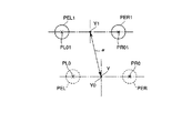
図9は観察者Dの左右の眼ER、ELの眼底反射光(瞳孔)の検出の原理を説明する説明図である。図9中で、参照符号PEL,PERは、赤外線カメラ51で撮像された観察者Dの左右の眼EL、ERの眼底反射光(瞳孔)の像を示す。さらに、図9中で、PLO,PROは左右の眼EL、ERの眼底反射光の中心点を示す。これらの中心点PRO,PLO間を結ぶ直線の中心位置Yが位置制御の基準位置である。そして、後述する初期位置設定スイッチ58をオン操作した場合にはそのスイッチ58の操作時点で検出される観察者Dの左右の眼ER、ELの中心点PRO,PLO間の中心位置Yが初期位置Y0として設定される。
FIG. 9 is an explanatory diagram for explaining the principle of detection of the fundus reflection light (pupil) of the left and right eyes ER and EL of the observer D. In FIG. 9, reference symbols PEL and PER indicate images of fundus reflection light (pupil) of the left and right eyes EL and ER of the observer D captured by the
また、表示パネル4の位置制御の開始時には観察者Dの左右の眼EL、ERの動きに合わせて表示パネル4の位置を移動させる制御が行なわれる。この表示パネル4の位置制御時には図8に示すように赤外線カメラ51で撮像された観察者Dの左右の眼EL、ERの眼底反射光の中心点PLO1,PRO1間の中心位置Y1が初期位置Y0からずれるズレ量αを検出することで、観察者Dの眼EL、ERの瞳孔PEL,PERの位置を検出するようになっている。
At the start of position control of the
また、瞳検出部52には、制御部46と第2のスイッチ57とが接続されている。ここで、制御部46には観察者Dの左右の眼EL、ERの動きに合わせて支持架台5の操作アーム8を動かして表示パネル4の位置を変更する表示パネル位置制御部(位置変更手段)47が設けられている。この表示パネル位置制御部47は、瞳検出部52による検出結果に応じて、支持架台5の操作アーム8の動作を制御するものである。第2のスイッチ57は、制御部46の表示パネル位置制御部47の動作をオンオフ操作するものである。第2のスイッチ57のオン操作時には上記表示パネル位置制御部47が駆動される。この第2のスイッチ57は、例えばフットスイッチFSWによって形成されている。
The
そして、表示パネル位置制御部47の駆動時には第3電磁ブレーキ31b、第4電磁ブレーキ38b、第5電磁ブレーキ41bによる操作アーム8の各軸受部31,38,41のロックが解除される。これにより、操作アーム8が中心軸O3、軸O4、軸O5の軸回り方向にそれぞれ回動自在な状態に切替えられる。この状態で、瞳検出部52による検出結果に応じて、第1モータ31mと、第2モータ38mと、第3モータ41mが駆動される。その結果、操作アーム8が中心軸O3、軸O4、軸O5回りの軸回り方向にそれぞれ回動され、表示パネル4が観察者Dの眼ER、ELの位置に向けられる状態で3次元的に移動される。このとき、表示パネル4は、S点位置は固定状態で保持され、このS点を中心に3次元的に移動される、いわゆるポイントロック状態で駆動される。そして、表示パネル位置制御部47によって表示パネル4と、この表示パネル4に表示される画像を観察する観察者Dの相対位置関係を一定に保つ状態、すなわち表示パネル4の中心と、観察者Dの左右の目EL,ERとの間の距離を一定に保つ状態で位置制御されるようになっている。
When the display
また、第2のスイッチ57のオフ操作時には表示パネル位置制御部47の駆動が停止される。そのため、第1モータ31mと、第2モータ38mと、第3モータ41mの駆動が停止され、第3電磁ブレーキ31b、第4電磁ブレーキ38b、第5電磁ブレーキ41bによって操作アーム8の各軸受部31,38,41がロックされる状態に切替え操作される。
Further, when the
さらに、制御部46には、表示パネル位置制御部47による表示パネル位置制御を開始する初期位置を設定する初期位置設定スイッチ58が接続されている。この初期位置設定スイッチ58は、グリップ部42eの下側の操作ボタン42gによってオンオフ操作される。
Further, an initial
そして、表示パネル位置制御部47による表示パネル位置制御時には開始前に予め表示パネル位置制御を開始する初期位置を設定する初期位置設定作業が行なわれる。この初期位置設定作業時には初期位置設定スイッチ58をオン操作することにより、その時点の観察者Dの左右の眼ER、ELの中心点PRO,PLO間の中心位置Yが初期位置Y0として制御部46に内蔵されているメモリに記憶され、表示パネル位置制御を開始する初期位置が設定されるようになっている。
Then, during the display panel position control by the display panel
次に、上記構成の本実施の形態の作用について説明する。術部Pの観察時には、術者などの観察者Dは、先ず、多関節アーム3を操作して撮像カメラ2の位置を術部Pに対して位置決め、固定する。その後、表示パネル4を任意の手術開始位置に配置固定する作業が行なわれる。
Next, the operation of the present embodiment having the above configuration will be described. When observing the surgical part P, an observer D such as an operator first operates the articulated arm 3 to position and fix the position of the
この作業時には表示パネル支持アーム42のグリップ部42eの上側の操作ボタン42fを押し込み操作して第1のスイッチ48をオン操作する。このとき、第1電磁ブレーキ9b、第2電磁ブレーキ21b、第3電磁ブレーキ31b、第4電磁ブレーキ38b、第5電磁ブレーキ41bによる操作アーム8の各軸受部9,21,31,38,41のロックが解除される。そのため、操作アーム8が3次元的に自由に移動可能な状態に切替え操作される。この状態で、支持架台5の操作アーム8を動かして表示パネル4を手術開始時の所望の位置に配置固定する。この際、表示パネル4を含む重量物は、カウンターウエイト32、22によって各回動軸回りに対して相殺されているため、術者は無重力感覚で表示パネル4の位置を変更することができる。なお、表示パネル4を手術開始位置に配置固定された状態では、表示パネル4のフレネル凹面鏡パネルで反射された後、結像位置P1に結像される左右の光学瞳OPL,OPRの位置に観察者(術者)Dの左右の目EL,ERを一致させることにより、プロジェクター43L、43Rから表示パネル4に投影される観察像が観察者Dによって3D(立体)観察される。
At this time, the
また、表示パネル4を任意の手術開始位置に移動したのち、操作ボタン42fの操作が解除されて第1のスイッチ48がオフ操作される。これにより、第1電磁ブレーキ9b、第2電磁ブレーキ21b、第3電磁ブレーキ31b、第4電磁ブレーキ38b、第5電磁ブレーキ41bが作動して操作アーム8の各軸受部9,21,31,38,41がロックされ、操作アーム8が固定状態に切替え操作される。そのため、表示パネル4が手術開始位置で固定された状態にセットされる。この状態で、手術が開始される。
Further, after the
この手術の開始時には、撮像カメラ2によって術部Pの観察が行なわれる。このとき、撮像カメラ2による観察像は左右のCCD44L,44Rに結像されて電気信号に変換され、カメラコントローラ45に出力される。カメラコントローラ45内ではこの電気信号に基づいて左右一対のCCU45L,45Rによって、左右一対の観察画像が生成される。さらに、左用のCCU45Lからの出力信号は左用のプロジェクター43Lに、右用のCCU45Rのからの出力信号は右用のプロジェクター43Rにそれぞれ入力される。そして、左右一対の観察画像のうち、右観察画像は、左側プロジェクター43L内の画像表示素子上に表示され、画像投影光学系によって表示パネル4上に右眼用表示画像として投影される。この右眼用の投影画像は、表示パネル4によって、観察者Dに向かって反射され、光学瞳OPRの結像位置P1に結像される。
At the start of this operation, the surgical site P is observed by the
同様に、術部Pの左観察画像は、右用のプロジェクター43R内の画像表示素子上に表示され、プロジェクター43Rの画像投影光学系によって表示パネル4に左眼用表示画像として投影される。この左眼用の投影画像は、表示パネル4によって、観察者Dに向かって反射され、光学瞳OPLの結像位置P1に結像される。そのため、表示パネル4のフレネル凹面鏡パネルで反射された後、結像位置P1に結像される左右の光学瞳OPL,OPRの位置に観察者(術者)Dの左右の目EL,ERを一致させることにより、プロジェクター43L、43Rから表示パネル4に投影される左右視差を持った画像を左右眼独立して観察することで、術部Pの立体観察が行われる。
Similarly, the left observation image of the surgical part P is displayed on an image display element in the
また、手術中に、観察者Dの眼ER、ELの位置に向けて表示パネル4を自動的に動かす表示パネル4の位置制御を行う場合にはその位置制御の開始前に予め初期位置設定作業が行なわれる。この初期位置設定作業時には、まず、グリップ部42eの下側の操作ボタン42gを押し込み操作して初期位置設定スイッチ58をオン操作する。
In addition, when performing position control of the
この操作時には位置検出手段49が駆動される。そして、赤外線光源50から赤外光の検査光が出射される。このとき、観察者Dの眼ER、ELの網膜56で反射された反射光(眼底反射光)が赤外線カメラ51の撮像光学系54を経て受光素子55に撮像される。これにより、赤外線カメラ51によって撮像される眼底反射光の中心点PRO,PLO間の中心位置Yの位置データが初期位置Y0として制御部46に内蔵されているメモリに記憶され、表示パネル位置制御を開始する初期位置Y0が設定される。
During this operation, the position detecting means 49 is driven. Then, infrared inspection light is emitted from the infrared
また、フットスイッチFSWが操作されると第2のスイッチ57がオン操作される。この第2のスイッチ57のオン操作時には、瞳検出部52が駆動される。この瞳検出部52の駆動時には、瞳検出部52からの制御信号によって赤外線光源50および赤外線カメラ51が駆動されるとともに、制御部46の表示パネル位置制御部47が駆動される。
When the foot switch FSW is operated, the
そして、初期位置設定作業時と同様に赤外線光源50から観察者Dに向けて赤外光の検査光が出射される。このとき、赤外線光源50から出射された赤外光の検査光は、観察者Dの眼ER、ELの網膜56で反射され、その反射光(眼底反射光)が赤外線カメラ51の撮像光学系54を経て受光素子55に撮像される。赤外線カメラ51の受光素子55に撮像された撮像信号は、瞳検出部52に入力される。この瞳検出部52では赤外線カメラ51によって撮像される眼底反射光の中心点PR1,PL1間の中心位置Yの測定値Y1が初期位置Y0からずれているズレ量αを検出することで、観察者Dの眼ER、ELの瞳孔の位置を検出する。これにより、表示パネル4に対する観察者Dの位置が検出される。
As in the initial position setting operation, infrared inspection light is emitted from the infrared
この瞳検出部52による検出結果に応じて、制御部46の表示パネル位置制御部47が駆動される。この表示パネル位置制御部47の駆動時には第3電磁ブレーキ31b、第4電磁ブレーキ38b、第5電磁ブレーキ41bによる操作アーム8の各軸受部31,38,41のロックが解除される。これにより、操作アーム8が中心軸O3、軸O4、軸O5の軸回り方向にそれぞれ回動自在な状態に切替えられる。この状態で、瞳検出部52による検出結果に応じて、第1モータ31mと、第2モータ38mと、第3モータ41mが駆動される。その結果、操作アーム8が中心軸O3、軸O4、軸O5回りの軸回り方向にそれぞれ回動され、表示パネル4が観察者Dの眼ER、ELの位置に向けられる状態で、3次元的に移動される。このとき、表示パネル位置制御部47によって表示パネル4と、この表示パネル4に表示される画像を観察する観察者Dの相対位置関係を一定に保つ状態で位置制御される。これにより、表示パネル4の向きが観察者Dの位置変化に追従する状態で、3次元的に移動される。
The display panel
また、第2のスイッチ57のオフ操作時には表示パネル位置制御部47の駆動が停止される。そのため、第1モータ31mと、第2モータ38mと、第3モータ41mの駆動が停止され、第3電磁ブレーキ31b、第4電磁ブレーキ38b、第5電磁ブレーキ41bによって操作アーム8の各軸受部31,38,41がロックされる状態に切替え操作される。
Further, when the
そこで、上記構成のものにあっては次の効果を奏する。すなわち、本実施の形態では瞳検出部52の駆動時には、瞳検出部52からの制御信号によって赤外線光源50および赤外線カメラ51が駆動されるとともに、制御部46の表示パネル位置制御部47が駆動される。このとき、表示パネル位置制御部47によって表示パネル4と、この表示パネル4に表示される画像を観察する観察者Dの相対位置関係を一定に保つ状態で位置制御する。これにより、観察者Dの位置変化に追従する状態で、支持架台5の操作アーム8を動かして表示パネル4の位置を変更することにより、観察画像を表示する表示パネル4を、手術の進行に対応して適切な位置に配置させることができる。そのため、術者などの観察者Dが自由に姿勢変更しても、常に、術部Pの拡大画像観察が可能である。このとき、観察者Dの姿勢変更に合わせて手動で表示パネル4の向きを変更する面倒な操作を行なう必要がないので、手術中の術者などの観察者Dの疲労軽減を図ることができる。さらに、FMDのような重量物を観察者Dの頭部につけることないので、疲労軽減効果を高めることができる。そのため、手術全体の作業効率の向上を図ることができる。
Therefore, the above configuration has the following effects. That is, in the present embodiment, when the
なお、上記実施の形態では、支持架台5の操作アーム8における等価運動機構として平行四辺形リンク10,11,12を用いて構成した場合で説明したが、これに限ることなく、その他、例えばタイミングベルトやギヤを用いて構成することも可能で、略同様の効果が期待される。また、このタイミングベルトやギヤを用いて等価運動機構を構成した場合には、上記平行四辺形リンクを用いて構成した場合に比してアームの細径化等を図ることが可能となる。上記平行四辺形リンク以外でも手動の操作に配慮したバランス機構であり、かつ観察者Dの左右の眼ER、ELの瞳の移動に追従して動作することができる構成であればよい。
In the above embodiment, the case where the parallel movement links 10, 11, and 12 are used as the equivalent motion mechanism in the
また、図10および図11は本発明の第2の実施の形態を示すものである。図10は、本実施の形態の画像観察装置を示すものである。本実施の形態は第1の実施の形態(図1乃至図9参照)の画像観察装置の構成を次の通り変更したものである。なお、この変更部分以外は第1の実施の形態の画像観察装置と同一構成になっている。そのため、第1の実施の形態の画像観察装置と同一部分には同一の符号を付してここではその説明を省略する。 10 and 11 show a second embodiment of the present invention. FIG. 10 shows an image observation apparatus according to the present embodiment. In the present embodiment, the configuration of the image observation apparatus of the first embodiment (see FIGS. 1 to 9) is changed as follows. Except for this changed portion, the configuration is the same as that of the image observation apparatus of the first embodiment. Therefore, the same parts as those in the image observation apparatus according to the first embodiment are denoted by the same reference numerals, and the description thereof is omitted here.
すなわち、本実施の形態では表示パネル4の支持架台5として手術室の天井部分61に吊り下げるシーリングマウント型の架台ベース62が設けられている。この架台ベース62に下向に吊り下げられた支柱63の下端部に第1の実施の形態と略同様の構成の操作アーム(表示手段支持部)64が取付けられている。
That is, in the present embodiment, a ceiling mount
この操作アーム64には第1の実施の形態と同様に3つ(第1,第2,第3の)の平行四辺形リンク10,11,12が設けられている。そして、第1の平行四辺形リンク10の縦アーム15の略中間部が支柱63の下端部に軸受部21を介して水平方向の軸O2回りに回動可能に支持されている。
The
なお、本実施の形態では2つの横アーム13,14は第1の実施の形態とは上下が逆に配置されている。そして、上側に配置された横アーム14の終端にカウンターウエイト22が設けられている。これ以外の第2,第3の平行四辺形リンク11,12の構成は第1の実施の形態と略同様である。
In the present embodiment, the two
また、本実施の形態では第1の実施の形態の位置検出手段49とは別の構成の位置検出手段が設けられている。本実施の形態の位置検出手段は、所謂ナビゲーション装置65によって構成されている。このナビゲーション装置65にはセンサアーム66と、ワークステーション67とが設けられている。センサアーム66には2つの赤外線カメラ68a,68bが内蔵されている。
In the present embodiment, a position detection unit having a configuration different from that of the
また、観察者Dの頭部には第1のナビゲーションセンサアーム69が取付けられている。このナビゲーションセンサアーム69には複数個の第1の発光ダイオード70が取付けられている。このナビゲーションセンサアーム69は、HMDに比べて重量が非常に軽いものである。そのため、観察者Dの頭部にナビゲーションセンサアーム69を取付けてもHMDのような不快感はない。
A first
さらに、表示パネル支持アーム42には第2のナビゲーションセンサアーム71が取付けられている。このナビゲーションセンサアーム71には複数個の第2の発光ダイオード72が取付けられている。図8に示すように各発光ダイオード70,72はLEDドライバ73を介してワークステーション67に接続されている。
Further, a second navigation sensor arm 71 is attached to the display
また、ワークステーション67には制御回路74が接続されている。この制御回路74は第1の実施の形態の制御部46と同様に構成されている。そして、この制御回路74には第1ドライバ75を介して第1モータ31m、第2ドライバ76を介して第2モータ38m、第3ドライバ77を介して第3モータ41mがそれぞれ接続されているとともに、第1の実施の形態の制御部46と同様に第1電磁ブレーキ9b、第2電磁ブレーキ21b、第3電磁ブレーキ31b、第4電磁ブレーキ38b、第1のスイッチ48、第2のスイッチ78、初期位置設定スイッチ79がそれぞれ接続されている。第2のスイッチ78は、ナビゲーション装置65の動作をオンオフ操作するものである。第2のスイッチ78のオン操作時には上記ナビゲーション装置65が駆動される。
A
本実施の形態では第1のスイッチ48は第1の実施の形態と同様にグリップアーム42dの上側の操作ボタン42fによってオンオフ操作されるようになっている。また、フットスイッチFSWには第2のスイッチ78および初期位置設定スイッチ79がそれぞれ設けられている。そして、初期位置設定スイッチ79によってそのスイッチ79の操作時点で検出される表示パネル4の位置と、観察者Dの頭部位置との相対的な位置関係が初期位置として設定される。
In the present embodiment, the
次に、上記構成の本実施の形態の作用について説明する。本実施の形態の画像観察装置の作用は大部分が第1の実施の形態と同様である。そして、ナビゲーション装置65の動作時には観察者Dの頭部の第1のナビゲーションセンサアーム69の第1の発光ダイオード70が点灯されるとともに、ナビゲーションセンサアーム71の第2の発光ダイオード72が点灯される。このとき、センサアーム66の赤外線カメラ68a,68bによって各発光ダイオード70,72からの赤外光が受光される。そして、赤外線カメラ68a,68bから出力される受光信号はワークステーション67に送信される。これにより、表示パネル4に対する観察者Dの相対的な位置が検出される。
Next, the operation of the present embodiment having the above configuration will be described. The operation of the image observation apparatus of the present embodiment is mostly the same as that of the first embodiment. During the operation of the
このワークステーション67による検出結果に応じて、制御回路74の表示パネル位置制御部47(図4参照)が駆動される。この表示パネル位置制御部47の駆動時には第3電磁ブレーキ31b、第4電磁ブレーキ38b、第5電磁ブレーキ41bによる操作アーム8の各軸受部31,38,41のロックが解除される。これにより、操作アーム8が中心軸O3、軸O4、軸O5の軸回り方向にそれぞれ回動自在な状態に切替えられる。この状態で、ナビゲーション装置65による検出結果に応じて、第1モータ31mと、第2モータ38mと、第3モータ41mが駆動される。その結果、操作アーム8が中心軸O3、軸O4、軸O5回りの軸回り方向にそれぞれ回動され、表示パネル4が観察者Dの眼ER、ELの位置に向けられる状態で、3次元的に移動される。このとき、表示パネル位置制御部47によって表示パネル4と、この表示パネル4に表示される画像を観察する観察者Dの頭部との相対位置関係を一定に保つ状態で位置制御される。これにより、表示パネル4の向きが観察者Dの頭部の位置変化に追従する状態で、3次元的に移動される。
The display panel position controller 47 (see FIG. 4) of the
なお、ナビゲーション装置65からの入力信号に応じて、表示パネル4および投影プロジェクター43L、43Rを懸垂する表示パネル支持アーム42の角度、位置を変更するアーム位置変更手段(エンコーダ、モーター)を設けてもよい。
It should be noted that arm position changing means (encoder, motor) for changing the angle and position of the display
そこで、上記構成のものにあっては次の効果を奏する。すなわち、本実施の形態でも術者などの観察者Dの頭部の位置に追従して、常に術者の瞳位置と表示パネル4による投影画像の射出瞳位置が一致するように、表示パネル4の位置が変更される。そのため、本実施の形態でも術者などの観察者Dが表示パネル4によって投影される射出瞳径以上移動しても、画像がケラレることがない。
Therefore, the above configuration has the following effects. That is, in this embodiment, the
さらに、術者などの観察者Dが顔だけを移動させた場合でも、表示パネル4が追従する。そのため、術者などの観察者Dが術部Pに対して自由に移動しても、常に術部Pの拡大画像を観察できる。
Further, the
さらに、本発明は上記実施の形態に限定されるものではなく、本発明の要旨を逸脱しない範囲で種々変形実施できることは勿論である。
次に、本出願の他の特徴的な技術事項を下記の通り付記する。
記
(付記項1) 電子画像を表示する画像表示手段と、それを観察する観察者の眼の相対位置関係を常に一定に保つ、相対位置固定手段を具備したことを特徴とする画像観察装置。
Furthermore, the present invention is not limited to the above-described embodiment, and various modifications can be made without departing from the scope of the present invention.
Next, other characteristic technical matters of the present application are appended as follows.
Record
(Additional Item 1) An image observation apparatus comprising: an image display unit that displays an electronic image; and a relative position fixing unit that constantly maintains a relative positional relationship between eyes of an observer who observes the electronic image.
(付記項2) 術部の拡大観察画像を表示する表示手段と、該表示手段を3次元的に自由な位置に配置固定する架台部とを有する画像観察装置において、前記表示手段と、該表示手段に表示される画像を観察する観察者の相対位置関係を一定に保つ、相対位置固定手段を有したことを特徴とする画像観察装置。 (Additional Item 2) In an image observation apparatus having display means for displaying an enlarged observation image of an operation part and a gantry for fixing the display means at a three-dimensional free position, the display means, and the display An image observing apparatus comprising a relative position fixing unit that keeps a relative positional relationship of an observer who observes an image displayed on the unit constant.
(付記項3) 前記相対位置固定手段が、前記表示手段に対する観察者の位置を検出する位置検出手段と、該位置検出手段による検出結果に応じて、前記表示手段の位置を変更する位置変更手段からなることを特徴とする付記項1または2に記載の画像観察装置。
(Additional Item 3) The relative position fixing unit detects a position of the observer with respect to the display unit, and a position changing unit that changes the position of the display unit according to a detection result by the position detection unit. Item 3. The image observation apparatus according to
(付記項1〜3が解決しようとする課題) 特許文献1に示すような手術用顕微鏡鏡体部にCCDを設け、その撮像画像を表示する表示手段(LCD)鏡体部に取り付けた場合、顕微鏡鏡体部にCCDを内蔵するスペースが必要となるばかりでなく、LCDを発光させるためのバックライト等を内蔵する必要があり、顕微鏡自体が大型化される。すなわち、術者が術部を処置する作業空間が犠牲になり、強いては手術効率の低下を招いていた。
(Problems to be solved by
さらに、特許文献2のように鏡体部内部にCCDのみ設け、表示手段と切り離した場合(別アームでの支持:特許文献1の第1図)や表示手段としてヘッドマウントディスプレー(以下HMD)を用いた場合(特許文献2の第4図)、前者では特許文献1に対して手術の処置作業空間は拡大されるが、術者の観察姿勢に応じて、接眼レンズを保持しているアームを配置し、さらに接眼レンズを覗き込むといった作業が必要となるため、結果、術者は術部の拡大観察時、常に顔を接眼レンズに対して顔を固定しておくといったことが必要となり、手術用顕微鏡の観察に対する疲労軽減は達成できない。また、後者のHMDの場合、常に、その表示手段は術者の眼に追従されるため、無理な観察姿勢を強いる必要はなくなる。しかしながら、術者はHMDといった、ある程度の重量を有する表示手段を顔に装着しておく必要があり、非常な疲労感や苦痛を強いることとなる。実際の手術においては術者は術部を直接観察する所謂直視と顕微鏡による拡大視察を繰り返したり、また、手術をアシストするアシスタントと連携を取りながら、手術の進行を行うが、HMDの場合、術者の眼に入る画像は常に、前述の拡大観察画像であるため、実際にそのようなことは行えず、結果、手術効率の低下を招いていた。
Further, as in
(付記項1〜3の目的) HMDのような重量物を装着するといった煩わしさを伴なうことなく、術者が自由に姿勢変更しても、常に、術部の拡大画像観察が可能な画像観察装置を提供する。
(Purpose of
本発明は、特に脳神経外科、眼科、整形外科等で使用される術部の拡大観察画像を表示する画像観察装置を使用する技術分野で有効である。 The present invention is particularly effective in the technical field using an image observation apparatus that displays an enlarged observation image of an operation part used in neurosurgery, ophthalmology, orthopedic surgery, and the like.
2…撮像カメラ、4…表示パネル(表示手段)、5…支持架台(架台部)、8…操作アーム(表示手段支持部)、9b…第1電磁ブレーキ(固定部)、21b…第2電磁ブレーキ(固定部)、31b…第3電磁ブレーキ(固定部)、38b…第4電磁ブレーキ(固定部)、41b…第5電磁ブレーキ(固定部)、47…表示パネル位置制御部(位置変更手段)、49…位置検出手段。
DESCRIPTION OF
Claims (5)
前記表示手段を3次元的に移動可能に支持する表示手段支持部と前記表示手段を自由な位置に配置した状態で係脱可能に固定する固定部とを有する架台部と、
前記表示手段に対する観察者の位置を検出する位置検出手段と、
前記位置検出手段による検出結果に応じて、前記架台部を動かして前記表示手段の位置を変更する位置変更手段とを具備することを特徴とする画像観察装置。 Display means for displaying an observation image of the surgical site;
A pedestal unit having a display unit support unit that supports the display unit movably in three dimensions and a fixing unit that removably fixes the display unit in a state where the display unit is disposed at a free position;
Position detecting means for detecting the position of an observer with respect to the display means;
An image observation apparatus comprising: a position changing unit that moves the gantry unit to change the position of the display unit according to a detection result by the position detection unit.
前記相対位置固定手段は、前記瞳検出部の検出結果に基いて前記観察者の位置変化に応じて前記観察者との相対位置関係を一定に保つ状態で前記位置変更手段を駆動する駆動手段を具備することを特徴とする請求項2に記載の画像観察装置。 The position detecting means detects a light irradiation unit that irradiates inspection light toward the observer's eye and reflected light that is reflected by the retina of the observer's eye from the light irradiation unit. A pupil detection unit that
The relative position fixing means is a driving means for driving the position changing means in a state where the relative positional relationship with the observer is kept constant according to a change in the position of the observer based on a detection result of the pupil detection unit. The image observation apparatus according to claim 2, further comprising:
前記表示手段に対する観察者の位置を検出する位置検出工程と、
前記位置検出工程による検出結果に応じて、前記表示手段支持部を動かして前記表示手段の位置を変更する位置変更工程と
を具備することを特徴とする画像観察位置の調整方法。 An initial setting step of three-dimensionally moving the display means for displaying the observation image of the surgical part by the display means support part and setting the display means at an arbitrary initial position;
A position detecting step for detecting the position of the observer with respect to the display means;
And a position changing step of changing the position of the display means by moving the display means support portion in accordance with the detection result of the position detection step.
Priority Applications (1)
| Application Number | Priority Date | Filing Date | Title |
|---|---|---|---|
| JP2004107250A JP2005292452A (en) | 2004-03-31 | 2004-03-31 | Image observing device and adjusting method of image observing position |
Applications Claiming Priority (1)
| Application Number | Priority Date | Filing Date | Title |
|---|---|---|---|
| JP2004107250A JP2005292452A (en) | 2004-03-31 | 2004-03-31 | Image observing device and adjusting method of image observing position |
Publications (1)
| Publication Number | Publication Date |
|---|---|
| JP2005292452A true JP2005292452A (en) | 2005-10-20 |
Family
ID=35325441
Family Applications (1)
| Application Number | Title | Priority Date | Filing Date |
|---|---|---|---|
| JP2004107250A Pending JP2005292452A (en) | 2004-03-31 | 2004-03-31 | Image observing device and adjusting method of image observing position |
Country Status (1)
| Country | Link |
|---|---|
| JP (1) | JP2005292452A (en) |
Cited By (6)
| Publication number | Priority date | Publication date | Assignee | Title |
|---|---|---|---|---|
| WO2012117922A1 (en) * | 2011-03-03 | 2012-09-07 | オリンパスメディカルシステムズ株式会社 | Medical holding device |
| JP2014523301A (en) * | 2011-06-27 | 2014-09-11 | ウェイブライト ゲーエムベーハー | Apparatus and method for eye surgery |
| WO2016017532A1 (en) * | 2014-08-01 | 2016-02-04 | ソニー・オリンパスメディカルソリューションズ株式会社 | Medical observation device |
| EP3412240A1 (en) * | 2017-06-08 | 2018-12-12 | Medicaroid Corporation | Remote control apparatus for medical equipment |
| JP2018202134A (en) * | 2018-01-25 | 2018-12-27 | 株式会社メディカロイド | Remote control device for medical instruments |
| JP2020151512A (en) * | 2018-01-25 | 2020-09-24 | 株式会社メディカロイド | Remote control device |
Citations (4)
| Publication number | Priority date | Publication date | Assignee | Title |
|---|---|---|---|---|
| JPH11239583A (en) * | 1998-02-25 | 1999-09-07 | Olympus Optical Co Ltd | Medical system |
| JP3209543B2 (en) * | 1990-07-13 | 2001-09-17 | オリンパス光学工業株式会社 | Surgical microscope |
| JP2003233143A (en) * | 2002-02-12 | 2003-08-22 | Olympus Optical Co Ltd | Viewing apparatus |
| JP2003329972A (en) * | 2002-05-17 | 2003-11-19 | Olympus Optical Co Ltd | Stereoscopic observation apparatus |
-
2004
- 2004-03-31 JP JP2004107250A patent/JP2005292452A/en active Pending
Patent Citations (4)
| Publication number | Priority date | Publication date | Assignee | Title |
|---|---|---|---|---|
| JP3209543B2 (en) * | 1990-07-13 | 2001-09-17 | オリンパス光学工業株式会社 | Surgical microscope |
| JPH11239583A (en) * | 1998-02-25 | 1999-09-07 | Olympus Optical Co Ltd | Medical system |
| JP2003233143A (en) * | 2002-02-12 | 2003-08-22 | Olympus Optical Co Ltd | Viewing apparatus |
| JP2003329972A (en) * | 2002-05-17 | 2003-11-19 | Olympus Optical Co Ltd | Stereoscopic observation apparatus |
Cited By (14)
| Publication number | Priority date | Publication date | Assignee | Title |
|---|---|---|---|---|
| JPWO2012117922A1 (en) * | 2011-03-03 | 2014-07-07 | オリンパスメディカルシステムズ株式会社 | Medical holding device |
| US8910913B2 (en) | 2011-03-03 | 2014-12-16 | Olympus Medical Systems Corp. | Supporting apparatus used medical treatment |
| WO2012117922A1 (en) * | 2011-03-03 | 2012-09-07 | オリンパスメディカルシステムズ株式会社 | Medical holding device |
| JP2014523301A (en) * | 2011-06-27 | 2014-09-11 | ウェイブライト ゲーエムベーハー | Apparatus and method for eye surgery |
| US10782501B2 (en) | 2014-08-01 | 2020-09-22 | Sony Olympus Medical Solutions Inc. | Medical observation device |
| WO2016017532A1 (en) * | 2014-08-01 | 2016-02-04 | ソニー・オリンパスメディカルソリューションズ株式会社 | Medical observation device |
| JPWO2016017532A1 (en) * | 2014-08-01 | 2017-05-25 | ソニー・オリンパスメディカルソリューションズ株式会社 | Medical observation device |
| US11287599B2 (en) | 2014-08-01 | 2022-03-29 | Sony Olympus Medical Solutions Inc. | Medical observation device |
| EP3412240A1 (en) * | 2017-06-08 | 2018-12-12 | Medicaroid Corporation | Remote control apparatus for medical equipment |
| US10653486B2 (en) | 2017-06-08 | 2020-05-19 | Medicaroid Corporation | Remote control apparatus for medical equipment |
| US10980604B2 (en) | 2017-06-08 | 2021-04-20 | Medicaroid Corporation | Remote control apparatus for medical equipment |
| JP2018202032A (en) * | 2017-06-08 | 2018-12-27 | 株式会社メディカロイド | Remote control apparatus for medical equipment |
| JP2018202134A (en) * | 2018-01-25 | 2018-12-27 | 株式会社メディカロイド | Remote control device for medical instruments |
| JP2020151512A (en) * | 2018-01-25 | 2020-09-24 | 株式会社メディカロイド | Remote control device |
Similar Documents
| Publication | Publication Date | Title |
|---|---|---|
| JP3905393B2 (en) | Surgical device | |
| KR102084276B1 (en) | Head-mounted display with tilt sensor for medical use | |
| US7633676B2 (en) | Stereomicroscope with coupling unit to swivel objective upon sensing movement of eyepiece | |
| JP2003233031A5 (en) | ||
| JP5054813B2 (en) | Optical observation device for observing eyes | |
| JP2019516138A (en) | Surgical 3D visualization system with head-mounted movable display | |
| US20200030054A1 (en) | Observation system for dental and medical treatment | |
| JP5870162B2 (en) | Imaging system | |
| JP3625906B2 (en) | Surgical microscope equipment | |
| US11432899B2 (en) | Medical observation device and medical observation system | |
| JP2016032485A (en) | Endoscopic surgery support system and image control method | |
| JP2008093433A (en) | Ophthalmic surgical microscope system | |
| WO2010079817A1 (en) | Stereo-endoscope | |
| JP4721981B2 (en) | Stereo microscope | |
| EP1524540A1 (en) | Image observation apparatus | |
| WO2019065700A1 (en) | Dental observation device and display method of dental image | |
| JP4383188B2 (en) | Stereoscopic observation system | |
| JP2004337247A (en) | Three-dimensional observation system | |
| JP4455419B2 (en) | Stereoscopic image observation device for surgery | |
| JP2005292452A (en) | Image observing device and adjusting method of image observing position | |
| JP6793623B2 (en) | Observation equipment, observation equipment, observation unit and medical care unit | |
| JP4002621B2 (en) | Surgical observation device | |
| JP4674094B2 (en) | Stereoscopic observation device | |
| JP4217650B2 (en) | Surgical microscope | |
| US11953669B2 (en) | Optical observation instrument and method for creating a stereo image of an object field |
Legal Events
| Date | Code | Title | Description |
|---|---|---|---|
| A621 | Written request for application examination |
Free format text: JAPANESE INTERMEDIATE CODE: A621 Effective date: 20070206 |
|
| A977 | Report on retrieval |
Free format text: JAPANESE INTERMEDIATE CODE: A971007 Effective date: 20100728 |
|
| A131 | Notification of reasons for refusal |
Free format text: JAPANESE INTERMEDIATE CODE: A131 Effective date: 20100810 |
|
| A02 | Decision of refusal |
Free format text: JAPANESE INTERMEDIATE CODE: A02 Effective date: 20101207 |