JP2005292450A - Projecting optical system and projecting exposure device - Google Patents
Projecting optical system and projecting exposure device Download PDFInfo
- Publication number
- JP2005292450A JP2005292450A JP2004107232A JP2004107232A JP2005292450A JP 2005292450 A JP2005292450 A JP 2005292450A JP 2004107232 A JP2004107232 A JP 2004107232A JP 2004107232 A JP2004107232 A JP 2004107232A JP 2005292450 A JP2005292450 A JP 2005292450A
- Authority
- JP
- Japan
- Prior art keywords
- optical system
- light transmission
- transmission plate
- light
- projection
- Prior art date
- Legal status (The legal status is an assumption and is not a legal conclusion. Google has not performed a legal analysis and makes no representation as to the accuracy of the status listed.)
- Granted
Links
- 230000003287 optical effect Effects 0.000 title claims abstract description 296
- 230000005540 biological transmission Effects 0.000 claims abstract description 221
- 239000000758 substrate Substances 0.000 claims abstract description 24
- 230000001678 irradiating effect Effects 0.000 claims abstract description 9
- 238000003384 imaging method Methods 0.000 claims description 16
- 238000009434 installation Methods 0.000 claims description 10
- 230000008859 change Effects 0.000 claims description 9
- VYPSYNLAJGMNEJ-UHFFFAOYSA-N Silicium dioxide Chemical compound O=[Si]=O VYPSYNLAJGMNEJ-UHFFFAOYSA-N 0.000 claims description 7
- 238000007789 sealing Methods 0.000 claims description 4
- 230000006866 deterioration Effects 0.000 abstract 1
- 230000007246 mechanism Effects 0.000 description 15
- 230000008602 contraction Effects 0.000 description 13
- 238000004364 calculation method Methods 0.000 description 11
- 238000005452 bending Methods 0.000 description 9
- 238000006243 chemical reaction Methods 0.000 description 6
- 238000010586 diagram Methods 0.000 description 6
- 230000000694 effects Effects 0.000 description 6
- 238000003860 storage Methods 0.000 description 6
- 239000011521 glass Substances 0.000 description 5
- 230000009467 reduction Effects 0.000 description 5
- 238000004519 manufacturing process Methods 0.000 description 4
- 239000000463 material Substances 0.000 description 4
- 230000004075 alteration Effects 0.000 description 3
- 230000014509 gene expression Effects 0.000 description 3
- 230000005484 gravity Effects 0.000 description 3
- XUIMIQQOPSSXEZ-UHFFFAOYSA-N Silicon Chemical compound [Si] XUIMIQQOPSSXEZ-UHFFFAOYSA-N 0.000 description 2
- 239000013256 coordination polymer Substances 0.000 description 2
- 239000004973 liquid crystal related substance Substances 0.000 description 2
- 238000000034 method Methods 0.000 description 2
- 229910052710 silicon Inorganic materials 0.000 description 2
- 239000010703 silicon Substances 0.000 description 2
- RYGMFSIKBFXOCR-UHFFFAOYSA-N Copper Chemical compound [Cu] RYGMFSIKBFXOCR-UHFFFAOYSA-N 0.000 description 1
- 238000007792 addition Methods 0.000 description 1
- 230000015572 biosynthetic process Effects 0.000 description 1
- 239000011889 copper foil Substances 0.000 description 1
- 230000003247 decreasing effect Effects 0.000 description 1
- 238000009826 distribution Methods 0.000 description 1
- 238000005516 engineering process Methods 0.000 description 1
- 239000003822 epoxy resin Substances 0.000 description 1
- 230000002349 favourable effect Effects 0.000 description 1
- 230000006872 improvement Effects 0.000 description 1
- 238000001459 lithography Methods 0.000 description 1
- 230000002093 peripheral effect Effects 0.000 description 1
- 229920002120 photoresistant polymer Polymers 0.000 description 1
- 229920000647 polyepoxide Polymers 0.000 description 1
- 230000007261 regionalization Effects 0.000 description 1
- 239000004065 semiconductor Substances 0.000 description 1
Images


Landscapes
- Exposure Of Semiconductors, Excluding Electron Or Ion Beam Exposure (AREA)
- Lenses (AREA)
- Exposure And Positioning Against Photoresist Photosensitive Materials (AREA)
Abstract
Description
本発明は、プリント配線板、LCD基板などの被処理基板に、マスクを介して紫外線を含む光を照射して所定パターンを露光して形成するときに使用される投影光学系および投影露光装置に関するものである。 The present invention relates to a projection optical system and a projection exposure apparatus used when a predetermined pattern is exposed by irradiating a substrate to be processed such as a printed wiring board or an LCD substrate with light including ultraviolet rays through a mask. Is.
一般的に、プリント配線基板、液晶パネル、液晶用のカラーフィルタなどの被処理基板の露光製造方法としては、所定のパターンを描画したマスクと、フォトレジストなどの感光材料を塗布した被処理基板とを密着した状態で、光源からの光を照射して露光作業を行なうフォトリソグラフィ法が採用されている。 In general, as an exposure manufacturing method for a substrate to be processed such as a printed wiring board, a liquid crystal panel, or a color filter for liquid crystal, a mask on which a predetermined pattern is drawn, and a substrate to be processed coated with a photosensitive material such as a photoresist, A photolithographic method is employed in which an exposure operation is performed by irradiating light from a light source in a state of being in close contact with each other.
ところが、近年の被処理基板は、製品に対応して軽薄、短小、高密度化に伴う多層化が進み、多層化したときの総合位置合わせ精度(オーバーレイヤー精度)が極めて高いレベルで要求されている。オーバーレイヤー精度が極めて高いレベルで要求される理由は、被処理基板が使用される各種の製品において多機能が求められ、その結果、軽薄、短小になったスペースに形成パターンが高密度化されることになり、各レイヤー(各層)での位置合わせ精度が製品の機能に与える影響が今まで以上に大きくなっていることによる。また、被処理基板は、素材の性質上(例えば、エポキシ樹脂と銅箔を使用)伸縮が生じやすいため、要求される精度の状態において、当該被処理基板の伸縮が各レイヤーの位置合わせ精度に対して無視できないものになってきている。 However, in recent years, substrates to be processed have become more and more thin, short, and multi-layered due to high density, and the total alignment accuracy (overlayer accuracy) when multi-layered is required at a very high level. Yes. The reason why the overlayer accuracy is required at a very high level is that a variety of products that use the substrate to be processed are required to have multiple functions. As a result, the formation pattern is densified in a thin, thin space. This is because the effect of the alignment accuracy on each layer (each layer) on the function of the product is greater than ever. In addition, because the substrate to be processed easily expands and contracts due to the nature of the material (for example, using epoxy resin and copper foil), the expansion and contraction of the substrate to be processed can increase the alignment accuracy of each layer in the required accuracy state. On the other hand, it is becoming something that cannot be ignored.
そのため、高密度化などの要望を満たすために半導体製造装置で実績のある投影露光装置が、プリント配線基板などの被処理基板用に対応して設計されて使用され、従来において、様々なものが提案されている。また、投影露光装置は、被処理基板の縦横の伸縮が一様であるときに、投影倍率を可変させることが比較的簡便にでき、そのため投影露光装置で用いられる投影光学系あるいは反射屈折投影光学系、さらに、マスクのパターンにおける投影像の倍率を補正する補正倍率光学系についても様々なものが提案されている。 Therefore, in order to satisfy the demand for higher density, projection exposure apparatuses that have a proven record in semiconductor manufacturing equipment are designed and used for substrates to be processed such as printed wiring boards. Proposed. In addition, the projection exposure apparatus can relatively easily change the projection magnification when the vertical and horizontal expansion and contraction of the substrate to be processed is uniform. Therefore, the projection optical system or the catadioptric projection optics used in the projection exposure apparatus can be used. Various correction magnification optical systems have also been proposed for correcting the magnification of the projection image in the mask pattern.
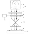
ここで従来の投影露光装置の一例について図8を参照して説明する。図8は、従来の投影露光装置の構成を模式的に示す模式図である。図8に示すように、従来の投影露光装置100は、紫外線を含む光を照射するための光源部101と、この光源部101から照射された光の光路中に配置されたマスクMと、このマスクMの直下に配置された補正倍率光学系104と、この補正倍率光学系104に隣り合う位置に配置され、照射される光に対して直交する平面において補正倍率光学系104を回転方向であるθ方向に移動させる回転機構105と、補正倍率光学系104の直下に配置された投影光学レンズ106と、この投影光学レンズ106の直下に配置される被処理基板であるワークWを載置する載置テーブル107と、を備えている。
Here, an example of a conventional projection exposure apparatus will be described with reference to FIG. FIG. 8 is a schematic diagram schematically showing a configuration of a conventional projection exposure apparatus. As shown in FIG. 8, a conventional
そして、投影露光装置100の補正倍率光学系104は、平行平面板102または一対の平行平面板102,103を対面させて備えており(図8では対面させた状態を示す)、平行平面板102を2次曲線形状に撓ませることで円筒面を形成した状態で配置されるか、あるいは、それぞれの平行平面板102,103を2次曲線形状に撓ませることで円筒面を形成し、それぞれの円筒面が互いに直交した状態で配置させている。なお、この補正倍率光学系104で使用される平行平面板102または平行平面板102,103は、シリンドリカルレンズに置き換えて配置した構成であってもよいものである(例えば、特許文献1参照)。
The correction magnification
なお、この投影露光装置100は、全体方向に同一の補正倍率を変化させる方式の装置と異なり、縦横の伸縮率が一様でないワークに対して特に有効となるものである。
しかし、従来の投影光学系あるいは投影露光装置では、さらに改良する余地があり、以下で示す問題を解決する必要があった。 However, the conventional projection optical system or projection exposure apparatus has room for further improvement, and it has been necessary to solve the following problems.
(1)従来の投影光学系は、光学的な配置関係を考えた場合に、光の入射される側にのみ補正倍率光学系が配置された状態であるため、補正倍率光学系の製作精度が大きく投影結像性能に影響を与えることになってしまった。そのため、補正倍率光学系の高精度加工、高精度の組立方法が必要となってしまった。また、このような構成の投影光学系では、光学的な配置関係上、対称性を持たない光学エレメントを変形させることでパターン形成を行なうことになるが、光学エレメントが対称となっていないため、パターン形状の伝達性にも影響を及ぼし、補正できる伸縮の幅が制限されることになってしまった。なお、投影光学系の補正倍率光学系にシリンドリカルレンズを用いることは、現状の技術レベルを考慮すると、必要とする精度を満足することが困難であり、現実的には適用が不可能である。 (1) Since the conventional projection optical system is in a state where the correction magnification optical system is disposed only on the light incident side when considering the optical arrangement relationship, the production accuracy of the correction magnification optical system is low. This greatly affects the projection imaging performance. Therefore, high-precision processing and a high-precision assembly method for the correction magnification optical system have become necessary. Further, in the projection optical system having such a configuration, on the optical arrangement relationship, pattern formation is performed by deforming an optical element having no symmetry, but the optical element is not symmetric, This also has an effect on the transmission of the pattern shape, which limits the range of expansion and contraction that can be corrected. Note that it is difficult to use the cylindrical lens for the correction magnification optical system of the projection optical system, considering the current technical level, and it is impossible to apply in practice.
(2)従来の投影光学系は、平行平面板を2次曲線状に湾曲させた状態で使用するため、平行平面板を装置の設置面に対して平行に配置する場合、あるいは、平行平面板を装置の設置面に対して直交して(垂直に)配置する場合のいずれであっても、当該平行平面板の自重または重力により変形状態を安定して維持することが困難であった。 (2) Since the conventional projection optical system is used in a state in which the parallel plane plate is curved in a quadratic curve, the parallel plane plate is arranged parallel to the installation surface of the apparatus, or the parallel plane plate It is difficult to stably maintain the deformation state due to the weight or gravity of the parallel flat plate in any case where the device is disposed perpendicularly (perpendicularly) to the installation surface of the apparatus.
(3)従来の投影露光装置は、用いられる投影光学系において、使用する補正倍率光学系が平行平面板を湾曲させた状態で配置し、光軸に直交する方向に回転させることで、倍率補正を行なっている構成であるため、補正倍率を変化させる場合には平行平面板を取り替える作業を行なう必要があり、作業効率が著しく悪い状態であった。また、投影露光装置において、シリンドリカルレンズを用いる補正倍率光学系のレンズ間の幅を調整することで、倍率補正を行なうものについては、前記したように、必要とする精度を満足する補正ができなかった。 (3) In the conventional projection exposure apparatus, in the projection optical system to be used, the correction magnification optical system to be used is arranged in a state where the parallel plane plate is curved, and rotated in a direction orthogonal to the optical axis, thereby correcting the magnification. Therefore, when changing the correction magnification, it is necessary to replace the plane-parallel plate, and the work efficiency is extremely poor. Further, in the projection exposure apparatus, as described above, correction that satisfies the required accuracy cannot be performed for those that perform magnification correction by adjusting the width between lenses of the correction magnification optical system using a cylindrical lens. It was.
本発明は、前記の問題点に鑑み創案されたものであり、補正倍率調整が容易で、補正倍率調整を行なうときに結像性能を劣化させることなく、また、補正できる幅が広く、さらに、補正倍率調整を安定した構成を維持して行なうことができる投影光学系、および、補正倍率調整などの作業効率に優れた投影露光装置を提供することを目的とする。 The present invention was devised in view of the above-mentioned problems, the correction magnification adjustment is easy, the image forming performance is not deteriorated when performing the correction magnification adjustment, and the width that can be corrected is wide. It is an object of the present invention to provide a projection optical system capable of performing correction magnification adjustment while maintaining a stable configuration, and a projection exposure apparatus excellent in work efficiency such as correction magnification adjustment.
本発明に係る投影光学系は、前記の問題を解決するため、つぎのように構成した。すなわち、投影光学系は、光源から照射された紫外線を含む光を、露光するパターンが描画されたマスクを透過させて投影光として、被処理基板の露光領域に対して照射する場合に用いられる投影光学系において、前記投影光の方向を変える第1反射面および第2反射面を所定角度に設けた反射体と、この反射体に対峙して配置され、前記第1反射面で反射した投影光を前記第2反射面に反射させる反射補正光学系と、この反射補正光学系の中心軸に対して対称となる一方の位置で、かつ、当該光学系が設置される設置面に対して垂直に配置され、前記第1反射面に前記投影光を透過して送る位置に設けた入射側凸レンズと、前記反射補正光学系の中心軸に対して対称となる他方の位置で、かつ、当該光学系が設置される設置面に対して垂直に配置され、前記第2反射面からの前記投影光を透過する位置に設けた出射側凸レンズと、前記投影光の前記入射側凸レンズに対面して設けられた第1光透過板を擬似円筒面状態に変形されることで、前記パターンの投影像の倍率補正を行なう第1補正倍率光学系と、前記投影光の前記出射側凸レンズに対面して設けられた第2光透過板を擬似円筒面状態に変形されることで、前記パターンの投影像の倍率補正を行なう第2補正倍率光学系と、を備え、前記入射側凸レンズの入射面側に第1光透過板が配置されたときに、前記出射側凸レンズの出射面側に第2光透過板が配置されるか、または、前記入射側凸レンズの出射面側に第1光透過板が配置されたときに、前記出射側凸レンズの入射面側に第2光透過板が配置される構成とした(請求項1)。 The projection optical system according to the present invention is configured as follows to solve the above problems. That is, the projection optical system is a projection used when light including ultraviolet rays emitted from a light source is transmitted as a projection light through a mask on which an exposure pattern is drawn and is irradiated onto an exposure area of the substrate to be processed. In the optical system, a reflector having a first reflection surface and a second reflection surface that change the direction of the projection light at a predetermined angle, and the projection light that is disposed opposite to the reflector and reflected by the first reflection surface. Is reflected on the second reflecting surface, and at one position that is symmetric with respect to the central axis of the reflecting correction optical system and perpendicular to the installation surface on which the optical system is installed An incident-side convex lens disposed at a position where the projection light is transmitted to the first reflecting surface and sent to the first reflecting surface; and the other position that is symmetric with respect to the central axis of the reflection correcting optical system, and the optical system Perpendicular to the installation surface An exit-side convex lens that is disposed and provided at a position that transmits the projection light from the second reflecting surface, and a first light transmission plate that faces the incident-side convex lens of the projection light is in a pseudo-cylindrical surface state The first correction magnification optical system for correcting the magnification of the projection image of the pattern and the second light transmission plate provided facing the exit-side convex lens for the projection light are transformed into a pseudo-cylindrical surface state. And a second correction magnification optical system that performs magnification correction of the projected image of the pattern, and when the first light transmission plate is disposed on the incident surface side of the incident-side convex lens, When the second light transmission plate is disposed on the exit surface side of the exit side convex lens, or when the first light transmission plate is disposed on the exit surface side of the entrance side convex lens, the entrance surface side of the exit side convex lens The second light transmission plate is disposed in the 1).
このように構成されることにより、投影光学系は、第1補正倍率光学系および入射側凸レンズを透過した投影光が、反射体の第1反射面により光路を水平方向から垂直方向に変更され反射補正光学系を介して再び反射体の第2反射面に反射される。そして、投影光学系は、投影光が、反射体の第2反射面により光路を垂直方向から水平方向に変えて反射され、出射側凸レンズおよび第2補正倍率光学系を透過してワークに向かって出射される。このとき、第1補正倍率光学系と第2補正倍率光学系とは、光学的な対称位置に配置されるととになり、光学的収差を打ち消す状態に配置されることになる。また、投影光学系は、マスクにおけるパターンの投影像について補正倍率を変更する場合には、光学的な対称性を有する位置に配置されたいずれか一方の光透過板を変形(擬似円筒面状態)させることで、当該パターンの投影像の縦あるいは横に対する倍率を変更している。 With this configuration, the projection optical system reflects the projection light transmitted through the first correction magnification optical system and the incident-side convex lens by changing the optical path from the horizontal direction to the vertical direction by the first reflecting surface of the reflector. The light is again reflected by the second reflecting surface of the reflector through the correction optical system. In the projection optical system, the projection light is reflected by the second reflecting surface of the reflector while changing the optical path from the vertical direction to the horizontal direction, and is transmitted through the exit-side convex lens and the second correction magnification optical system toward the workpiece. Emitted. At this time, the first correction magnification optical system and the second correction magnification optical system are arranged at optically symmetric positions, and are arranged so as to cancel the optical aberration. Further, when changing the correction magnification for the projected image of the pattern on the mask, the projection optical system deforms one of the light transmission plates arranged at a position having optical symmetry (pseudo cylindrical surface state). By doing so, the magnification with respect to the vertical or horizontal direction of the projected image of the pattern is changed.
また、本発明に係る投影光学系において、前記入射側凸レンズに対面して配置された前記第1光透過板と、この第1光透過板を、シール枠体を介して保持する第1保持手段とを備え、前記第2補正倍率光学系は、前記出射側凸レンズに対面して配置された前記第2光透過板と、この第2光透過板を、シール枠体を介して保持する第2保持手段とを備え、前記第1保持手段、前記シール枠体、第1光透過板ならびに前記入射側凸レンズで囲繞される密閉空間、または、前記第2保持手段、前記シール枠体、第2光透過板ならびに前記出射側凸レンズで囲繞される密閉空間のそれぞれの気圧を調整して前記第1光透過板または前記第2光透過板を、前記シール枠体のそれぞれを介して平板状態から擬似円筒面状態に変形させる変形手段を備える構成とした(請求項2)。なお、変形手段は、それぞれの密閉空間の気圧をおのおの調整する第1変形手段および第2変形手段の構成としても構わない(請求項3)。 Further, in the projection optical system according to the present invention, the first light transmission plate disposed to face the incident-side convex lens, and first holding means for holding the first light transmission plate via a seal frame. The second correction magnification optical system includes a second light transmission plate disposed to face the exit-side convex lens and a second light transmission plate that holds the second light transmission plate via a seal frame. Holding means, a sealed space surrounded by the first holding means, the seal frame, the first light transmission plate and the incident side convex lens, or the second holding means, the seal frame, and the second light The first light transmissive plate or the second light transmissive plate is adjusted from the flat plate state through the seal frame body by adjusting the air pressure in the sealed space surrounded by the transmissive plate and the exit-side convex lens. A structure provided with a deformation means for deforming to a surface state And the (claim 2). The deforming means may be configured as first deforming means and second deforming means for adjusting the air pressure in each sealed space, respectively (claim 3).
このように構成されることにより、投影光学系は、変形手段(第1変形手段)により密閉空間の気圧を調整することで、第1保持手段に保持されている第1光透過板の全面が気圧で押されシール枠体を介して平板状態から擬似円筒面状態に変形して補正レンズの構成となり、マスクにおけるパターンの投影像に対する倍率が補正される。同様に、投影光学系は変形手段(第2変形手段)により密閉空間の気圧を調整することで、第2保持手段に保持されている第2光透過板の全面が気圧で押され、シール枠体を介して平板状態から擬似円筒面状態に変形して補正レンズの構成となり、マスクにおけるパターンの投影像に対する倍率が補正される。投影光学系は、例えば、パターンの投影像の横方向における倍率を縮小補正するときに、第1光透過板を平板状態から擬似円筒面状態に変形させることで対応でき、また、第2光透過板を平板状態から擬似円筒面状態に変形させることで、パターンの投影像の横方向においける倍率を拡大補正できるようにしている。なお、密閉空間の気圧を増圧にすること、あるいは気圧を負圧にすることにより、各光透過板を擬似円筒面状態に変形している。 With this configuration, the projection optical system adjusts the air pressure in the sealed space by the deformation means (first deformation means), so that the entire surface of the first light transmission plate held by the first holding means is It is pushed by atmospheric pressure and deformed from a flat plate state to a pseudo-cylindrical surface state via a seal frame to form a correction lens, and the magnification of the pattern with respect to the projected image on the mask is corrected. Similarly, the projection optical system adjusts the air pressure in the sealed space by the deformation means (second deformation means), so that the entire surface of the second light transmission plate held by the second holding means is pushed by the air pressure, and the seal frame The flat lens state is changed to the pseudo cylindrical surface state via the body to form a correction lens, and the magnification of the pattern on the mask with respect to the projected image is corrected. For example, the projection optical system can cope with the reduction of the magnification in the horizontal direction of the projected image of the pattern by changing the first light transmission plate from the flat plate state to the pseudo-cylindrical surface state. By deforming the plate from the flat plate state to the pseudo cylindrical surface state, the magnification in the horizontal direction of the projected image of the pattern can be enlarged and corrected. Note that each light transmission plate is deformed into a quasi-cylindrical surface state by increasing the pressure of the sealed space or by setting the pressure to a negative pressure.
さらに、本発明に係る投影光学系において、前記第1保持手段は、前記投影光を通過させる開口窓を有し前記入射側凸レンズに沿って配置される枠本体と、この枠本体の開口窓に沿って設置され前記第1光透過板を設ける前記シール枠体と、このシール枠体および前記第1光透過板を挟持すると共に、前記第1光透過板に対応して開口を有する挟持枠体と、前記第1光透過板を擬似円筒面状態に湾曲させる方向にガイドし、前記光透過板の湾曲頂部に対して対称となる位置で前記挟持枠体と前記光透過板の間に設けられたガイドバーと、を備え、前記第2保持手段は、前記投影光を通過させる開口窓を有し、前記出射側凸レンズに沿って配置される枠本体と、この枠本体の開口窓に沿って設置され前記第2光透過板を設ける前記シール枠体と、このシール枠体および前記第2光透過板を挟持すると共に、前記第2光透過板に対応して開口を有する挟持枠体と、前記第2光透過板を擬似円筒面状態に湾曲させる方向にガイドし、前記光透過板の湾曲頂部に対して対称となる位置で前記挟持枠体と前記光透過板の間に設けられたガイドバーと、を備える構成とした(請求項4)。 Further, in the projection optical system according to the present invention, the first holding unit includes a frame body having an opening window that allows the projection light to pass therethrough and disposed along the incident-side convex lens, and an opening window of the frame body. The seal frame body provided along with the first light transmission plate and the sandwiching frame body sandwiching the seal frame body and the first light transmission plate and having an opening corresponding to the first light transmission plate And a guide provided between the sandwiching frame body and the light transmission plate at a position symmetrical with respect to the curved top of the light transmission plate. The second holding means has an opening window that allows the projection light to pass therethrough, and is disposed along the opening window of the frame body, the frame body being disposed along the exit-side convex lens. The seal frame provided with the second light transmission plate; While sandwiching the seal frame and the second light transmission plate, the holding frame body having an opening corresponding to the second light transmission plate and the second light transmission plate in a direction to bend into a pseudo cylindrical surface state. The guide is configured to include a guide bar provided between the sandwiching frame body and the light transmission plate at a position that is symmetrical with respect to the curved top portion of the light transmission plate.
このように構成されることにより、投影光学系は、第1補正倍率光学系を作動させる場合、第1光透過板側の密閉空間の気圧を調整して高めることで、その第1光透過板の全面を押圧して、平板状態から擬似円筒面状態に変形させる。変形する際に第1光透過板は、湾曲頂部に対して対称となる位置のガイドバーが、枠本体および挟持枠体により挟持されることで、そのガイドバーが接触した状態となる。そのため、第1光透過板の左右となる対称の位置では平板状態の部分がガイドバーによって保とうとし、また、ガイドバーがない第1光透過板の上下の辺では、湾曲しようとする圧力が直接働き、第1光透過板を擬似円筒面状態に湾曲させている。なお、第1光透過板のガイドバーがない位置では、シール枠体が第1光透過板の変形に追随するため、密閉空間の気密性は保たれることになる。また、各光透過板を擬似円筒面状態に変形させるために、ガイドバーが各光透過板の擬似凸円筒面状態および擬似凹円筒面状態の両方をガイドする位置に配置されても構わない。 With this configuration, when the first correction magnification optical system is operated, the projection optical system adjusts and raises the pressure of the sealed space on the first light transmission plate side, thereby increasing the first light transmission plate. The whole surface is pressed to deform from a flat plate state to a pseudo cylindrical surface state. When the first light transmission plate is deformed, the guide bar at a position that is symmetrical with respect to the curved top is sandwiched between the frame body and the sandwiching frame so that the guide bar comes into contact. For this reason, at the symmetrical positions on the left and right sides of the first light transmission plate, the flat portion is intended to be held by the guide bar, and at the upper and lower sides of the first light transmission plate without the guide bar, the pressure to be bent is directly applied. The first light transmission plate is bent into a pseudo cylindrical surface state. Note that, in the position where the guide bar of the first light transmission plate is not provided, the seal frame follows the deformation of the first light transmission plate, so that the airtightness of the sealed space is maintained. Further, in order to deform each light transmission plate into a pseudo cylindrical surface state, the guide bar may be arranged at a position for guiding both the pseudo convex cylindrical surface state and the pseudo concave cylindrical surface state of each light transmission plate.
また、本発明に係る投影光学系において、前記第1光透過板の擬似円筒面状態と、前記第2光透過板の擬似円筒面状態とが互いに直交するように配置する構成とした(請求項5)。
このように構成されることにより、投影光学系は、第1光透過板または第2光透過板のいずれか一方を擬似円筒面状態に湾曲させることで、例えば、マスクにおけるパターンの投影像について横方向の倍率補正を行い、他方を擬似円筒面状態に湾曲させることで、マスクにおけるパターンの投影像について縦方向の倍率補正を行なっている。
In the projection optical system according to the present invention, the pseudo-cylindrical surface state of the first light transmission plate and the pseudo-cylindrical surface state of the second light transmission plate are arranged so as to be orthogonal to each other (claims). 5).
By being configured in this way, the projection optical system can, for example, laterally project a pattern projection image on the mask by curving either the first light transmission plate or the second light transmission plate into a pseudo cylindrical surface state. The magnification correction in the direction is performed, and the other is curved in a quasi-cylindrical surface state, whereby the magnification correction in the vertical direction is performed on the projected image of the pattern on the mask.
さらに、本発明に係る投影光学系において、前記第1光透過板および前記第2光透過板は、曲率無限大の合成石英ガラス板が用いられ、前記合成石英ガラス板の長辺をDとし、その中心厚みをdとし、かつ、当該投影光学系における最大の主光線傾角をωとしたとき、つぎの式(1)である1<{(d/D)×100}<10…式(1)と、つぎの式(2)である0.01<(ω2×d)<2.5…式(2)の条件を満足する構成とした(請求項6)。 Furthermore, in the projection optical system according to the present invention, the first light transmission plate and the second light transmission plate are synthetic quartz glass plates having infinite curvature, and the long side of the synthetic quartz glass plate is D, When the center thickness is d and the maximum chief ray tilt angle in the projection optical system is ω, the following equation (1) 1 <{(d / D) × 100} <10 (1) ) And 0.01 <(ω 2 × d) <2.5, which is the following expression (2): (2).
このように構成されることにより、投影光学系は、ガラス板の機械的な特性を、そのガラス板の長辺と厚み、特に中心厚みとの関係を規定することで、ガラス板を擬似円筒面状態に湾曲するときの湾曲のし易さと破損との関係を好ましい範囲に設定している。それと同時に、投影光学系は、主光線傾角ωとガラス板の中心厚みdとの関係を規定することで、ガラス板の湾曲したときの補正能力および歪曲との関係を好ましい範囲に設定している。 By being configured in this way, the projection optical system defines the mechanical properties of the glass plate by defining the relationship between the long side of the glass plate and the thickness, particularly the center thickness, thereby making the glass plate a pseudo-cylindrical surface. The relationship between the ease of bending and the breakage when bending to a state is set in a preferable range. At the same time, the projection optical system defines the relationship between the chief ray tilt angle ω and the center thickness d of the glass plate, thereby setting the relationship between the correction capability and distortion when the glass plate is curved within a preferable range. .
そして、本発明に係る投影光学系において、前記第1光透過板または前記第2光透過板は、前記シール枠体との関係において、EGを第1または第2光透過板のヤング率とし、ESをシール枠体のヤング率とし、TGを第1または第2光透過板の板厚とし、TSをシール枠体の厚みとし、νGを第1または第2光透過板のポアソン比とし、νSをシール枠体のポアソン比としたとき、つぎの式(3)で示す条件、
このように構成されることにより、投影光学系は、曲げの剛性式を基本として各光透過板の擬似円筒面状態をより理想に近づけるためにシール枠体の厚みとシール枠体の物質的な特性とを好ましい範囲に設定している。 By being configured in this way, the projection optical system is based on the bending stiffness formula, and the thickness of the seal frame and the material of the seal frame are made closer to the ideal quasi-cylindrical surface state of each light transmission plate. The characteristics are set in a preferable range.
また、本発明に係る投影光学系において前記入射側凸レンズおよび前記出射側凸レンズは、前記密閉空間の気圧を調整して、それぞれの光透過板が擬似円筒面状態であるときに、それぞれの凸レンズの変形比率が0.2%以下であるような厚みを備える構成とした(請求項8)。
このように構成されることにより、投影光学系は、第1光透過板および第2光透過板のそれぞれが、密閉空間の気圧を調整されて平板状態から擬似円筒面状態に湾曲したときに、入射側凸レンズおよび出射側凸レンズに対しての圧力による変形が、圧力の変化する前と比較して、光学性能上無視できる状態の範囲で、かつ、好適な補正効果を期待できるものとなる。
Further, in the projection optical system according to the present invention, the incident-side convex lens and the exit-side convex lens adjust the atmospheric pressure of the sealed space, and when each light transmitting plate is in a pseudo-cylindrical surface state, The thickness is such that the deformation ratio is 0.2% or less (claim 8).
By being configured in this manner, the projection optical system is configured such that each of the first light transmission plate and the second light transmission plate is curved from the flat plate state to the pseudo-cylindrical surface state by adjusting the air pressure in the sealed space. The deformation due to the pressure on the incident-side convex lens and the outgoing-side convex lens is in a state where it can be ignored in terms of optical performance as compared with before the pressure changes, and a favorable correction effect can be expected.
さらに、本発明に係る投影光学系において、前記第1光透過板および前記第2光透過板における前記投影光の光路に対する有効透過設定範囲は、擬似円筒面状態としたときに、当該第1光透過板および当該第2光透過板の周縁から内側に向かってあらかじめ設定される位置に設けられた構成とした(請求項9)。
このように構成されることにより、投影光学系は、擬似円筒面状態とした際、マスクの倍率を補正する場合に有効となる第1光透過板あるいは第2光透過板のより好ましい範囲に投影光の光路を設定できるようになる。
Furthermore, in the projection optical system according to the present invention, when the effective transmission setting range with respect to the optical path of the projection light in the first light transmission plate and the second light transmission plate is a pseudo cylindrical surface state, the first light It was set as the structure provided in the position preset beforehand toward the inner side from the periphery of the permeation | transmission board and the said 2nd light permeation | transmission board (Claim 9).
With this configuration, when the projection optical system is in the quasi-cylindrical surface state, the projection optical system projects in a more preferable range of the first light transmission plate or the second light transmission plate that is effective when correcting the magnification of the mask. The light path can be set.
そして、本発明に係る投影露光装置は、光源から照射された紫外線を含む光を、露光するパターンが描画されたマスクを透過させて投影光として、前記パターンを形成する被処理基板の露光領域に対して照射する投影露光装置において、前記被処理基板と前記マスクにあらかじめ形成されているそれぞれの整合マークを撮像する撮像手段と、前記ワークと前記マスクの間に設けられた投影光学系と、この投影光学系の入射側および出射側にそれぞれ設置された、前記マスクにおけるパターンの投影像の倍率を補正する第1補正倍率光学系および第2補正倍率光学系と、前記撮像手段により撮像した前記各マークの映像情報に基づいて、前記補正倍率光学系を制御する制御手段と、を備える構成とした(請求項10)。なお、前記第1補正倍率光学系は、前記投影光学系の入射側凸レンズに対面して密閉空間を介して設けた第1光透過板を備え、前記第2補正倍率光学系は、前記投影光学系の出射側凸レンズに対面して密閉空間を介して設けた第2光透過板を備え、前記密閉空間のそれぞれの気圧を調整して、前記第1光透過板または前記第2光透過板を平板状態から擬似円筒状態に変形させる変形手段を備え、前記制御手段は、前記映像情報に基づいて、前記変形手段を制御する構成としても構わない(請求項11)。 In the projection exposure apparatus according to the present invention, light including ultraviolet rays emitted from a light source is transmitted as a projection light through a mask on which a pattern to be exposed is drawn, and is applied to an exposure region of a substrate to be processed on which the pattern is formed. In the projection exposure apparatus that irradiates the image, an imaging means for imaging the alignment marks formed in advance on the substrate to be processed and the mask, a projection optical system provided between the workpiece and the mask, and A first correction magnification optical system and a second correction magnification optical system, which are installed on the incident side and the emission side of the projection optical system, respectively, for correcting the magnification of the projected image of the pattern on the mask; And a control means for controlling the correction magnification optical system based on the image information of the mark. The first correction magnification optical system includes a first light transmission plate provided through a sealed space facing the incident side convex lens of the projection optical system, and the second correction magnification optical system includes the projection optical system. A second light transmission plate provided through a sealed space facing the output side convex lens of the system, and adjusting each atmospheric pressure of the sealed space, the first light transmission plate or the second light transmission plate A deformation means for deforming from a flat plate state to a pseudo-cylindrical state may be provided, and the control means may be configured to control the deformation means based on the video information.
このように構成されることにより、投影露光装置では、はじめに撮像手段により両マークを撮像した映像情報により被処理基板の伸縮状態を制御手段が認識するとともに、第1補正倍率光学系または第2補正倍率光学系のいずれかを制御してパターンの投影像の倍率を補正している。このときの、両補正倍率光学系は、投影光学系に対して光学的に対称な位置に配置された状態で、倍率補正を行なっている。また、両補正倍率光学系の密閉空間を制御手段からの制御により変形手段が調整する、つまり、密閉空間の気圧を増減することにより、第1光透過板または第2光透過板を平板状態から擬似円筒面状態に湾曲させて変化させることで、光学的な対称性を維持した状態で倍率補正を行なっている。 With this configuration, in the projection exposure apparatus, the control means recognizes the expansion / contraction state of the substrate to be processed based on the video information obtained by first imaging both marks by the imaging means, and the first correction magnification optical system or the second correction. The magnification of the projected image of the pattern is corrected by controlling any one of the magnification optical systems. At this time, both correction magnification optical systems perform magnification correction in a state where they are arranged at optically symmetrical positions with respect to the projection optical system. Further, the deformation means adjusts the sealed space of both correction magnification optical systems by control from the control means, that is, the first light transmission plate or the second light transmission plate is moved from the flat state by increasing or decreasing the pressure of the sealed space. By changing the curve to a pseudo-cylindrical surface state, magnification correction is performed while maintaining optical symmetry.
なお、投影光学系を、第1反射面および第2反射面を所定角度に設けた反射体と、この反射体に対峙して配置した反射補正光学系と、反射補正光学系の中心軸に対して対称となる一方と他方に、設置面に対して垂直に配置される入射側凸レンズおよび出射側凸レンズとを備える反射屈性投影光学系としても構わない。そのため、露光装置では、光源からの光が、照射されて反射鏡およびフライアイレンズなどを介してマスクを通過し、投影光として第1補正光学系および入射側凸レンズから投影光学系に入射する。そして、投影露光装置では、投影光学系において一旦、反射体の第1反射面により投影光の向きを水平方向から垂直方向に変えて反射し、再び投影光を垂直方向から水平方向に補正反射光学系により反射し、反射体の第2反射面により投影光を垂直方向から水平方向に変える。さらに、投影露光装置では、反射体の第2反射面から反射された投影光を、出射側凸レンズおよび第2補正倍率光学系を介して基板保持テーブルに垂直に保持されている被処理基板に対して照射する。 Note that the projection optical system includes a reflector having the first reflecting surface and the second reflecting surface provided at a predetermined angle, a reflection correcting optical system disposed opposite to the reflector, and a central axis of the reflection correcting optical system. The reflection-reflective projection optical system may be provided with an incident side convex lens and an output side convex lens arranged perpendicular to the installation surface on one side and the other side that are symmetrical to each other. Therefore, in the exposure apparatus, the light from the light source is irradiated and passes through the mask via the reflecting mirror and the fly-eye lens, and enters the projection optical system as projection light from the first correction optical system and the incident-side convex lens. In the projection exposure apparatus, the projection optical system temporarily reflects the projection light by changing the direction of the projection light from the horizontal direction to the vertical direction by the first reflecting surface of the reflector, and again corrects the projection light from the vertical direction to the horizontal direction. The light is reflected by the system, and the projection light is changed from the vertical direction to the horizontal direction by the second reflecting surface of the reflector. Further, in the projection exposure apparatus, the projection light reflected from the second reflecting surface of the reflector is applied to the substrate to be processed that is vertically held on the substrate holding table via the exit-side convex lens and the second correction magnification optical system. Irradiate.
また、投影露光装置は、マスクにおけるパターンの投影像の倍率を補正するとき、例えば、マスクにおける投影像の横方向のスケールを縮小するときには、入射側凸レンズに対面する第1補正倍率光学系を作動させ密閉空間の気圧を調整することで第1光透過板を平板状態から擬似円筒面状態に湾曲させる。また、マスクにおける投影像の横方向のスケールを拡大するときには、出射側凸レンズに対面する第2補正倍率光学系を作動させ、密閉空間の気圧を調整することで、第2光透過板を平板状態から湾曲状態に湾曲させるものである。なお、投影露光装置では、投影光学系がマスクおよび被処理基板の間において対称に各エレメントを配置していることにより、入射側での歪曲を出射側において吸収することができる関係となっている。 The projection exposure apparatus operates the first correction magnification optical system facing the incident side convex lens when correcting the magnification of the projected image of the pattern on the mask, for example, when reducing the horizontal scale of the projected image on the mask. The first light transmission plate is bent from the flat plate state to the pseudo-cylindrical surface state by adjusting the air pressure in the sealed space. Further, when the scale in the horizontal direction of the projected image on the mask is enlarged, the second light transmission plate is in a flat state by operating the second correction magnification optical system facing the exit-side convex lens and adjusting the air pressure in the sealed space. To bend into a curved state. In the projection exposure apparatus, since the projection optical system arranges each element symmetrically between the mask and the substrate to be processed, the distortion on the incident side can be absorbed on the emission side. .
本発明に係る投影光学系および投影露光装置では、以下に示すように優れた効果を奏するものである。
(1)投影光学系は、反射体および反射補正光学系を中央として対称となる位置に入射側凸レンズおよび出射側凸レンズが配置され、第1補正倍率光学系および第2補正倍率光学系についても光学的な対称となる位置に配置されているため、一方の補正倍率光学系の光透過板を擬似円筒面状態にすることで例えばマスクにおける投影像の横方向のスケールを縮小(拡大)させる方向に補正でき、また、他方の補正倍率光学系の光透過板を擬似円筒面状態にすることで、パターンの投影像の横方向のスケールを拡大(縮小)させる方向に補正できる。また、投影光学系の両補正倍率光学系は、設置面に対して垂直に配置されているため、自重や重力の影響が最小限となり補正精度を維持した状態で動作することができる。なお、投影光学系では、両補正倍率光学系が、光学的に対称に配置されているため、補正倍率光学系を動作させるときに、光学的収差を打ち消すように補正が行なわれることになる。また、投影光学系は、補正の幅が、従来のものと比較して広く調整することが可能となる。もちろん、投影光学系は、光学的な非対称の配置と比較して高精度な加工や組立ては必要としない。
The projection optical system and the projection exposure apparatus according to the present invention have excellent effects as described below.
(1) In the projection optical system, the incident-side convex lens and the exit-side convex lens are arranged at positions symmetrical with respect to the reflector and the reflection correction optical system, and the first correction magnification optical system and the second correction magnification optical system are also optical. Since the light transmission plate of one of the correction magnification optical systems is in a quasi-cylindrical surface state, for example, in the direction of reducing (enlarging) the horizontal scale of the projected image on the mask. In addition, by making the light transmission plate of the other correction magnification optical system in a pseudo-cylindrical surface state, correction can be made in the direction in which the horizontal scale of the projected image of the pattern is enlarged (reduced). In addition, since both correction magnification optical systems of the projection optical system are arranged perpendicular to the installation surface, the influence of the weight and gravity can be minimized and the correction accuracy can be maintained. In the projection optical system, since both correction magnification optical systems are optically symmetrically arranged, correction is performed so as to cancel the optical aberration when the correction magnification optical system is operated. In addition, the projection optical system can be adjusted with a wider correction range than the conventional one. Of course, the projection optical system does not require high-precision processing and assembly as compared with the optically asymmetric arrangement.
(2)投影光学系は、密閉空間の気圧の調整により第1光透過板または第2光透過板を、平板状態から擬似円筒面状態にシール枠体を介して湾曲させてレンズの働きもたせるようにしてパターンの投影像の倍率を補正しているため、各光透過板を変形させる調整が容易であると共に、変形させるときの各光透過板に対する機械的な付加を分散することで光透過板に対する付加を最小限とし、各補正倍率光学系の精度を維持して補正倍率の調整を可能にしている。
(3)投影光学系は、両光透過板を平板状態から擬似円筒面状態に湾曲させるときに、ガイドバーを介して密閉空間の気圧を調整することで行なっているため、理想に近い円筒面を形成でき、補正倍率光学系の繰り返し動作を行なっても補正精度を維持して補正精度の一層の向上を可能とする。さらに、投影光学系は、擬似円筒面を互いに直交するように配置することで、パターンの投影像に対する縦と横の倍率が個々に補正できる。また、投影光学系は、均等変倍をするための機構が不要となる。
(2) In the projection optical system, the first light transmission plate or the second light transmission plate is bent from the flat plate state to the pseudo-cylindrical surface state via the seal frame body by adjusting the atmospheric pressure of the sealed space so that the lens functions as well. Since the magnification of the projected image of the pattern is corrected, the adjustment for deforming each light transmission plate is easy, and the light transmission plate is dispersed by dispersing mechanical additions to each light transmission plate at the time of deformation. The correction magnification can be adjusted while maintaining the accuracy of each correction magnification optical system.
(3) Since the projection optical system is configured by adjusting the air pressure in the sealed space via the guide bar when the two light transmission plates are bent from the flat plate state to the pseudo cylindrical surface state, the cylindrical surface is close to ideal. The correction accuracy can be maintained and the correction accuracy can be further improved even if the correction magnification optical system is repeatedly operated. Furthermore, the projection optical system can individually correct the vertical and horizontal magnifications with respect to the projected image of the pattern by arranging the pseudo cylindrical surfaces so as to be orthogonal to each other. Further, the projection optical system does not require a mechanism for performing uniform magnification.
(4)投影光学系は、機械変形の特性を、光透過板の板厚みと長辺との関係で規定すると共に、補正能力および歪曲の特性を、主光線傾角と板厚みとの関係で規定しているため、より調整し易く、かつ、補正倍率精度の優れた補正倍率光学系を提供することが可能となる。
(5)投影光学系は、各光透過板およびシール枠体の材質と厚みの関係を所定の値とすることで規定しているため、密閉空間の気圧の調整でより適切となる擬似円筒面状態を形成することが可能となり、理想に近い円筒面を提供でき補正倍率の調整を行なうときに有利となる。
(4) The projection optical system defines the mechanical deformation characteristics by the relationship between the plate thickness and the long side of the light transmission plate, and the correction capability and distortion characteristics by the relationship between the chief ray tilt angle and the plate thickness. Therefore, it is possible to provide a correction magnification optical system that is easier to adjust and has excellent correction magnification accuracy.
(5) Since the projection optical system defines the relationship between the material and thickness of each light transmission plate and seal frame to a predetermined value, a pseudo cylindrical surface that is more suitable for adjusting the atmospheric pressure of the sealed space It is possible to form a state, and it is possible to provide a nearly ideal cylindrical surface, which is advantageous when adjusting the correction magnification.
(6)投影光学系は、各凸レンズと各光透過板との厚さの関係を規定することで、各凸レンズに対する気圧の影響を最小限にでき、各凸レンズの変形が光学的性能上において無視できる状態となり、密閉空間の気圧を調整して各光透過板の形状を変形させる動作を行っても他の光学エレメントに与える影響を最小限とすることができる。
(7)投影光学系は、各光透過板を平板状態から擬似円筒面状態として湾曲させたとき、投影光の光路をあらかじめ設定された有効透過設定範囲としているため、倍率補正を行なうときに有効に使用できる補正レンズとしての円筒曲面部分を利用することができ、補正精度をより向上させることが可能となる。
(6) By defining the thickness relationship between each convex lens and each light transmission plate, the projection optical system can minimize the effect of atmospheric pressure on each convex lens, and the deformation of each convex lens is ignored in terms of optical performance. Even if the operation of changing the shape of each light transmission plate by adjusting the air pressure in the sealed space is performed, the influence on other optical elements can be minimized.
(7) When the projection optical system is curved from the flat plate state to the quasi-cylindrical surface state, the projection optical system sets the optical path of the projection light within the preset effective transmission setting range, and is therefore effective when performing magnification correction. A cylindrical curved surface portion as a correction lens that can be used for the correction can be used, and the correction accuracy can be further improved.
(8)投影露光装置は、各補正倍率光学系が光学的な対称となる位置に配置されているため、一方の補正倍率光学系を調整することで例えばパターンにおける投影像の横方向のスケールを縮小させる方向に補正でき、また、他方の補正倍率光学系を調整することで、例えば、パターンにおける投影像の横方向のスケールを拡大させる方向に補正できる。また、投影光学系の両補正倍率光学系は、両マークの映像情報に基づいて制御手段により制御されるため、ワークの伸縮に適切でかつ速やかに対応することができ、従来の構成と比較して作業性に優れている。 (8) Since the projection exposure apparatus is arranged at a position where each correction magnification optical system is optically symmetric, by adjusting one correction magnification optical system, for example, the horizontal scale of the projected image in the pattern can be adjusted. Correction can be made in the direction of reduction, and by adjusting the other correction magnification optical system, for example, correction can be made in the direction of enlarging the horizontal scale of the projected image in the pattern. In addition, since both the correction magnification optical systems of the projection optical system are controlled by the control means based on the image information of both marks, it is possible to respond appropriately and quickly to the expansion and contraction of the workpiece, compared with the conventional configuration. Excellent workability.
また、投影露光装置は、その両補正倍率光学系が、密閉空間を調整することで光透過板を平板状態から擬似円筒面状態に湾曲させるように動作させて倍率補正を行なっており、自重や重力の影響が最小限となり補正精度を維持した状態で動作することができる。なお、投影露光装置の投影光学系では、両補正倍率光学系が、光学的に対称に配置されているため、補正倍率光学系を動作させるときに、光学的収差を打ち消すように補正が行なわれることになる。さらに、投影露光装置では、それぞれの光透過板の擬似円筒面状態を、撮像手段による映像情報に基づいて制御手段からの制御により、変形手段が密閉空間の気圧の調整により行っているため、補正倍率についても固定されることなく調整できる。 Further, the projection exposure apparatus performs magnification correction by operating both the correction magnification optical systems so as to bend the light transmission plate from the flat plate state to the pseudo cylindrical surface state by adjusting the sealed space. It is possible to operate in a state where the influence of gravity is minimized and the correction accuracy is maintained. In the projection optical system of the projection exposure apparatus, since both correction magnification optical systems are optically symmetrically arranged, correction is performed so as to cancel the optical aberration when the correction magnification optical system is operated. It will be. Further, in the projection exposure apparatus, the pseudo cylindrical surface state of each light transmission plate is controlled by the control means based on the image information by the imaging means, and the deformation means is adjusted by adjusting the atmospheric pressure in the sealed space. The magnification can also be adjusted without being fixed.
以下、本発明を実施するための最良の形態を、図面を参照して説明する。
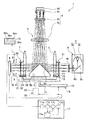
図1は投影露光装置の各エレメントの配置を模式的に示す模式図、図2は投影光学系の分解斜視図、図3(a)は投影光学系の第1光透過板、シール枠体、入射側凸レンズの厚みの関係を模式的に示す断面図、(b)は第1光透過板の長辺の長さおよび擬似円筒面状態のときの円筒頂部を模式的に示す模式図、図4は投影光学系の投影光に対する有効光路面積を説明する正面図である。なお、ここでは、はじめに投影光学系Aについて説明し、その後、投影露光装置1について説明することとする。
The best mode for carrying out the present invention will be described below with reference to the drawings.
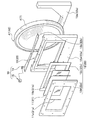
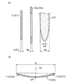
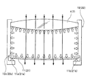
FIG. 1 is a schematic view schematically showing the arrangement of each element of the projection exposure apparatus, FIG. 2 is an exploded perspective view of the projection optical system, and FIG. 3A is a first light transmission plate, a seal frame of the projection optical system, FIG. 4B is a cross-sectional view schematically showing the relationship between the thicknesses of the incident-side convex lenses, FIG. 4B is a schematic view schematically showing the length of the long side of the first light transmission plate and the top of the cylinder in the pseudo-cylindrical surface state. FIG. 5 is a front view for explaining an effective optical path area with respect to projection light of the projection optical system. Here, the projection optical system A will be described first, and then the
図1に示すように、投影露光装置1の投影光学系Aは、マスクMとワークWの間に各光学エレメントが対称となるように設置されている。この投影光学系Aは、中央に配置される反射体5の上方に対峙して反射補正光学系6を図示しないフレームに支持させて配置して備えると共に、その反射補正光学系6の中心軸に対して対称となる位置に入射側凸レンズ4および出射側凸レンズ7を備え、かつ、入射側凸レンズ4に対面して第1補正倍率光学系A1と、出射側凸レンズ7に対面して第2補正倍率光学系A2と、を備えている。なお、光学エレメントとは、ここでは投影光を透過、反射するものをいう。
As shown in FIG. 1, the projection optical system A of the
入射側凸レンズ4および出射側凸レンズ7は、反射体5を中央として共軸に配置されており、それぞれが単レンズとして配置され、両面凸レンズが用いられている。入射側凸レンズ4および出射側凸レンズ7は、同一の屈折率となるようにここでは構成されている。
そして、入射側凸レンズ4は、反射体5の第1反射面5aに投影光を透過して送る位置に配置されている。なお、入射側凸レンズ4は、ここではレンズ中央から下方のみが投影光に対して有効な光路となるように設定されている。
また、出射側凸レンズ7は、ここでは両面凸レンズが用いられ、反射体5の第2反射面5bから反射される投影光を透過させる位置に配置されている。この出射側凸レンズ7は、入射側凸レンズ4と同様に中央から下方のみが投影光に対して有効な光路となるように設定されている。
The incident-side
The incident-side
The exit-side
反射体5は、光路の向きを変えるものであり、入射側凸レンズ4から透過されてきた投影光を、水平方向から垂直方向に反射して変えるように所定角度で形成された第1反射面5aと、この第1反射面5aに隣接して、反射補正光学系6から送られて来た投影光を、垂直方向から水平方向に反射してその向きを変えるように所定角度で形成された第2反射面5bとを備えている。なお、この反射体4は、入射側凸レンズ4から出射側凸レンズ7まで投影光の光路を確保できる状態であれば、その形状および製造方法について特に限定されるものではない。
The
反射補正光学系6は、補正光学系である第1凸レンズ6a、平凸レンズ6bと、凹レンズ6cとを共軸に備えると共に、その凹レンズ6cに対面した位置に凹面反射ミラー6dを配置して備えている。この反射補正光学系6は、凹面反射ミラー6dが、設置される入射側凸レンズ4、反射体5、補正光学系(6a、6b、6c)などの配置により、設置高さ、焦点距離が設定されるものであり、ここでは、入射側凸レンズ4および出射側凸レンズ7の焦点距離faとしたときに、凹面反射ミラー6dの焦点距離fbとの比率関係が絶対値において、1.2<fa/fb<5.5の関係を満足する位置関係となるように配置されることが好ましい。凹面反射ミラー6dは、1.2<fa/fb<5.5の範囲に設置されると、テレセントリック性(主光軸の平行性)が維持できる状態を容易に確保でき都合がよい。なお、補正光学系である各レンズ6a,6b,6cは、それぞれ単レンズで構成されている。また、反射補正光学系6は、全体として補正光学系(6a、6b、6c)が正の屈折力をもつものであればよい。
The reflection correction
図1および図2に示すように、第1補正倍率光学系A1と、第2補正倍率光学系A2とは、それぞれ同一の光学エレメントを用いて光学的に対称となる位置に配置されている。第1補正倍率光学系A1は、ここでは合成石英ガラス板で形成した第1光透過板11と、この第1光透過板11を平板状態から擬似円筒面状態に変形自在にシール枠体12cを介して保持する第1保持手段12と、この第1保持手段12、第1光透過板11および入射側凸レンズ4とで囲繞される密閉空間13とを備えている。そして、この第1補正倍率光学系A1の密閉空間13は、接続管14を介して設けられた調整手段15を有する変形手段16により気圧の調整が行なわれるものである。
As shown in FIGS. 1 and 2, the first correction magnification optical system A1 and the second correction magnification optical system A2 are arranged at optically symmetrical positions using the same optical elements. Here, the first correction magnification optical system A1 includes a first
同様に、第2補正倍率光学系A2は、ここでは合成石英ガラス板で形成した第2光透過板21と、この第2光透過板21を平板状態から擬似円筒面状態に変形自在にシール枠体22cを介して保持する第2保持手段22と、この第1保持手段22、第2光透過板21および出射側凸レンズ7とで囲繞される密閉空間23とを備えており、密閉空間23の気圧が、接続管14を介して設けた調整手段15を備える変形手段16により調整されるものである。なお、ここは、前記した調整手段15を第1補正倍率光学系A1と共有している構成として説明する。もちろん調整手段15は、それぞれの補正倍率光学系A1,A2が各々備える構成としても構わない。
Similarly, the second correction magnification optical system A2 includes a second
第1光透過板11は、合成石英ガラス板など露光作業に必要な所定波長の紫外線を透過させることができる光透過部材であればよい。この第1光透過板11は、入射側凸レンズ4との関係では、密閉空間13の気圧の調整を行なったときに、入射側凸レンズ4に対する変形比率が0.2%以下である板厚の関係であることが望ましい。すなわち、入射側凸レンズ4では、密閉空間13の気圧の調整を行ったときに、入射側凸レンズ4の変形比率が0.2%を超えない範囲であると、投影光の屈折の変化量が無視できる範囲となるからである。つまり、入射側凸レンズが圧力により変形しても、光学性能上無視できる状態の範囲であり、かつ、他の光学エレメントと併せて好適な補正効果を期待できるものを維持できる状態である。ちなみに、第1光透過板11と、入射側凸レンズ4との厚みの関係は、一例として、第1光透過板11が5mmであったときに、入射側凸レンズ4が最大肉厚部40mm、最小肉厚部25mmとしている。この場合、密閉空間13の気圧の調整を行なって6.5kPaの付加を与え、第1光透過板11を擬似円筒面状態に湾曲させても、入射側凸レンズ4が変形前と変形後ではその変形比率は、0.2%以下となる。
The first
また、この第1光透過板11は、投影光の光軸に直交する透過面積(LD×LT、図4参照)より広い面積となる長方形(正方形を含む四角形あるいは矩形)に形成され、図3(a),(b)に示すように、所定の板厚(中心厚)dとしたときに、長辺Dとの関係が、式(1)示す1<{(d/D)×100}<10となるように設定され、かつ、投影光の主光線傾角ωと板厚d(中心厚)との関係が式(2)で示す0.01<(ω2×d)<2.5の条件を満たすように設定されることが好ましい。
1<{(d/D)×100}<10 式(1)
0.01<(ω2×d)<2.5 式(2)
Further, the first
1 <{(d / D) × 100} <10 Formula (1)
0.01 <(ω 2 × d) <2.5 Formula (2)
第1光透過板11は、長辺Dと板厚dとの関係で式(1)において比率が「1」を越えるようにならないと、機械的な強度が保つことが困難になりやすく、また、平板状態から擬似円筒面状態に湾曲させる場合に密閉空間を制御することが困難になりやすい状態となる。また、第1光透過板11は、式(1)において比率が「10」以下であると機械的な強度を保った状態で変形するときに特に制御することが容易となる。したがって、長辺Dと板厚dとの関係が式(1)を満たすことが特に好ましい。
If the ratio does not exceed “1” in the formula (1) due to the relationship between the long side D and the plate thickness d, the first
第1光透過板11は、さらに、式(2)において(ω2×d)が「0.01」を越えると、主光線傾角ωを非常に小さくする必要がなくなり、設計上好ましい状態となる。また、第1光透過板11は、式(2)において(ω2×d)が「2.5」未満であると、歪曲が0.002%を越える場合がほとんどなく、歪曲が小さい状態が維持でき、リソグラフィー技術に適用するには最適な範囲となる。そのため、第1光透過板11は、式(1)、式(2)の条件を満足することが好ましい。
なお、第2光透過板21の板厚、その他の構成、および、出射側凸レンズ7との関係は、すでに説明した第1光透過板11と同じであるため、その説明を省略する。
Further, when (ω 2 × d) in Formula (2) exceeds “0.01”, the first
Note that the thickness of the second
図2に示すように、第1保持手段12は、ここでは入射側凸レンズ4を擬似円筒面状態に変形可能に保持すると共に第1光透過板11を保持するように構成されており、入射側凸レンズ4に沿って配置され開口窓を有する枠本体12aと、この枠本体12aの開口窓に沿って取り付けられるシール枠体12cと、このシール枠体12cを介して設けられる第1光透過板11と、この第1光透過板11の光路となる位置に開口を有する挟持枠体12dと、第1光透過板11の左右端(擬似円筒面状態としたときの円筒頂部に対して対称)となる位置に配置されたガイドバー11a,11bと、を備えている。なお、この第1保持手段12は、入射側凸レンズ4を枠本体12aとで挟持するレンズ挟持枠体12eも、ここでは備えている。そして、この第1保持手段12は、枠本体12aの上端に補助フレーム12bが取付けられるように構成されており、この補助フレーム12bが入射側凸レンズ4の凸曲面に沿って当接してシールするように構成されている。なお、補助フレーム12bは、枠本体12aと一体に形成される構成としても構わない。
As shown in FIG. 2, the 1st holding means 12 is comprised so that the incident side
ここで使用されるシール枠体12cと第1光透過板11との関係は、曲げ剛性比であるつぎの式(3)に示す条件、つまり、
シール枠体12cは、式(3)において、左辺の値を超えないと存在しないことになり、また、右辺の値未満であると、第1光透過板11が目的とする擬似円筒面状態に湾曲することが容易となるため、式(3)の条件を満足することが望ましい。ちなみに、ここでは、一例として、シール枠体12cと第1光透過板11との曲げ剛性比を、1対50000に設定しており、この場合では、第1光透過板11が5mmであり、シール枠体12cをシリコンシートで形成したときに、そのシリコンシートの厚みを3mm程度まで許容できるようになるものである。
The
ガイドバー11a,11b(21a,21b)は、第1光透過板11の一端から他端に亘って当接する長さを備えており、ここでは断面円形に形成されている。このガイドバー11a,11bは、同じ長さ、同じ断面形状となるように形成されており、図3(b)に示すように、第1光透過板11の湾曲頂部CPに対して対称となる位置に配置されている。なお、このガイドバー11a,11bの断面形状は、三角形、四角形、楕円形など各光透過板11,21に当接して擬似円筒面状態にガイドできる形状であれば、円形に限定あれるものではない。また、ガイドバー11a,11bの長さについても同様で、第1光透過板11の一端から他端に亘って当接する長さでなくても、第1光透過板11が適切に擬似円筒面状態になれば良い。
また、このガイドバー11a、11b(21a,21b)は、第1光透過板11の一方側にのみ配置した構成として説明したが、その第1光透過板11の両側で対面する配置されていても構わない。
The guide bars 11a and 11b (21a and 21b) have a length that abuts from one end to the other end of the first
The guide bars 11 a and 11 b (21 a and 21 b) have been described as being configured only on one side of the first
なお、第2補正倍率光学系A2側の構成、すなわち、第2光透過板21および第2保持手段22などは、すでに説明したものと同じ構成であるため、符号の十の位を2として付して(図2参照)、構成の説明は省略する。
The configuration on the second correction magnification optical system A2 side, that is, the second
そして、図2および図5に示すように、第1補正倍率光学系A1は、第1光透過板11、第1保持手段12および入射側凸レンズ4により囲繞される密閉空間13が形成され、この密閉空間13の気圧を変形手段16により調整することで、第1光透過板11を平板状態から擬似円筒面状態、あるいは、擬似円筒面状態から平板状態に変形させて、パターンの投影像のスケールを倍率補正している。なお、図1に示すように、第1補正倍率光学系A1および第2補正倍率光学系A2のそれぞれの密閉空間13,23は、ここでは変形手段16により気圧の調整をそれぞれ行なうように構成されている。もちろん、各密閉空間13,23を別々の図示しない変形手段(第1変形手段、第2変形手段)により調整する構成としても構わない。
2 and 5, the first correction magnification optical system A1 is formed with a sealed
変形手段16は、各密閉空間13,23に一端が接続される接続管14と、この接続管14の他端に接続されるコンプレッサあるいは真空ポンプなどの調整手段15とを備えており、図示していないが、必要な位置に、切換弁、リーク弁などを備えている。
The deformation means 16 includes a connecting
なお、図1に示すように、この変形手段16では、第1光透過板11および第2光透過板21が、例えば、板厚dが5mmであったときに、密閉空間13,23に1〜6.5kPaの気圧をさらに負荷することで、第1光透過板11または第2光透過板21を平板状態から擬似円筒面状態に湾曲させることができるものである。なお、密閉空間13,23に負圧、つまりマイナス1〜6.5kPaの気圧を減圧することで凸面を凹面とする擬似円筒面状態に湾曲させることも可能である。
As shown in FIG. 1, in this deformation means 16, when the first
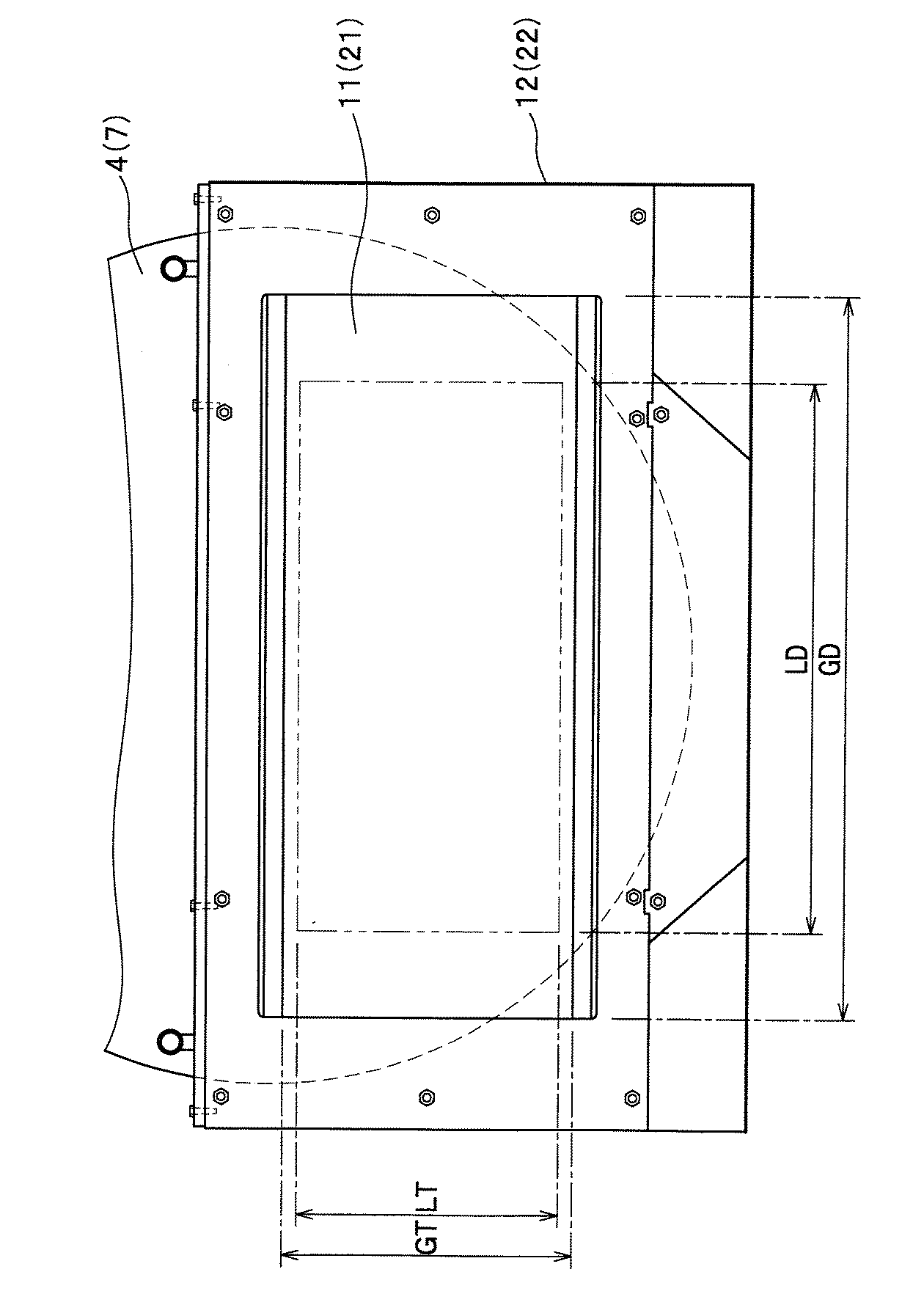
また、図4に示すように、投影光の光路は、第1光透過板11および第2光透過板21において、有効透過設定範囲となるようにあらかじめ設定されていることが好ましい。すなわち、両光透過板11,21は、平板状態から擬似円筒面状態に湾曲してマスクM(図1参照)のパターンの投影像についての倍率補正を行なっているため、理想円筒面をできるだけ有効に使用することが望ましく、第1光透過板11および第2光透過板21の周縁であるGT,GDから内側にシフトした領域LT,LDに有効透過設定範囲を設定している。なお、有効透過設定範囲は、必要な条件を加味して計算した範囲で設定することや、また、実際に投影光をワークW(図1参照)の露光領域に照射して設定することや、その両者により設定しても構わない。
Further, as shown in FIG. 4, it is preferable that the optical path of the projection light is preset in the first
また、図1に示すように、両凸レンズ4,7および両補正倍率光学系A1,A2は、支持移動機構30に支持されて、入射側凸レンズ4および出射側凸レンズ7を、所定間隔を維持した状態で、光軸方向に対して平行に移動するように構成されていても構わない。この支持移動機構30は、両凸レンズ4,7および両補正倍率光学系A1,A2を支持する支持手段31と、この支持手段31を移動するための案内レール32と、この案内レール32に沿って前記支持手段31を移動させるための駆動手段33とを備えており、両凸レンズ4,7および両補正倍率光学系A1,A2を光軸方向に沿って平行に移動できる構成(例えば、送りねじ機構、スライド機構など)であれば特に限定されるものではない。
Further, as shown in FIG. 1, the
つぎに、投影光学系Aの作用を説明する。
図1に示すように、投影光学系Aに対して投影光が送られてくると、その投影光は、はじめに第1補正倍率光学系A1の第1光透過板11を透過して入射側凸レンズ4を透過して反射体5の第1反射面5aに到達する。このとき、第1補正光学系A1では、第1光透過板11を平板状態としており、倍率補正を行なっていない状態である。そして、投影光は、反射体5の第1反射面5aにより水平方向から垂直方向に反射される。
Next, the operation of the projection optical system A will be described.
As shown in FIG. 1, when projection light is sent to the projection optical system A, the projection light first passes through the first
反射体5の第1反射面5aにより反射された投影光は、補正光学系(6a,6b,6c)および凹面反射ミラー6dを介して、反射体5の第2反射面5bに送られる。このとき、補正光学系(6a,6b,6c)は、正の屈曲力を持つように配置され、また、凹面反射ミラー6dの焦点距離および入射側凸レンズ2(出射側凸レンズ3)の焦点距離との比の関係において、所定の条件を満足していることから、テレセントリック性(主光線の平行性)を保った状態を維持することができる。
The projection light reflected by the first reflecting
そして、反射補正光学系6を介して送られて来た投影光は、反射体5の第2反射面5bにより、垂直方向から水平方向に向きを変えられた状態で反射して、出射側凸レンズ7および第2補正倍率光学系A2の第2光透過板21を透過して出射する。このとき、第2補正光学系A2では、第2光透過板21を平板状態としており、倍率補正を行なっていない状態である。そのため、投影光は、マスクMのパターンにおける投影像を1対1の状態でワークWに照射して露光できる状態となる。
Then, the projection light transmitted via the reflection correction
つぎに、第1補正倍率光学系A1を作動させたときの作用を説明する。なお、ここで示す投影光学系Aでは、第1補正倍率光学系A1を作動させると、設置されているマスクMのパターンにおける投影像について横方向の倍率が縮小するように設定されている。
マスクMとワークWとの位置合わせを行うときに、それぞれのワークマークWm,マスクマークMm(整合マーク(図1参照))をアライメントする際、ワークWの伸縮状態が判断されて、ワークWの伸縮状態に対応させて倍率補正を行なうことになる。例えば、設置されたワークWの横方向の寸法が0.01%縮小されていた場合には、その縮小率に関する情報が変形手段16側に制御手段17を介して伝達され、その縮小率に合わせて変形手段16の調整手段15が密閉空間13の気圧を調整する。
Next, an operation when the first correction magnification optical system A1 is operated will be described. In the projection optical system A shown here, when the first correction magnification optical system A1 is operated, the lateral magnification of the projection image in the pattern of the mask M that is installed is set to be reduced.
When aligning the mask M and the workpiece W, when the workpiece mark Wm and the mask mark Mm (alignment mark (see FIG. 1)) are aligned, the expansion / contraction state of the workpiece W is determined, and the workpiece W The magnification correction is performed corresponding to the expansion / contraction state. For example, when the horizontal dimension of the installed work W has been reduced by 0.01%, information on the reduction ratio is transmitted to the deformation means 16 side via the control means 17 and matched with the reduction ratio. Thus, the adjusting means 15 of the deforming means 16 adjusts the air pressure in the sealed
第1光透過板11は、密閉空間13の気圧が調整されて増加したときには、図5(a)に示す状態から、図5(b)に示す状態となるように、平板状態から擬似円筒面状態に湾曲する。なお、一例として、第1光透過板11が5mmであったときには、密閉空間13の気圧を1〜6.5kPa増加させることにより、第1光透過板11の中心位置CLにおいて形成される円筒頂部CP(図3(b)参照)において平面から最大1.6mm程度の湾曲状態とする擬似円筒面状態に湾曲することができる。なお、一例として、第1光透過板11が1mm撓んだ状態の擬似円筒面を形成すると、20μm〜30μmの倍率の調整を行なうことが可能となる。また、このとき湾曲する際には、左右のガイドバー11a,11bにより円筒面になるように案内されていることと、投影光の有効光路設定範囲が第1光透過板11の周縁から内側にシフトして設定されていることにより、より理想となる第1光透過板11の円筒面部分が使用されることになる。ちなみに、一例として、第1光透過板11が横390mm、縦170mmであったときに、有効光路設定範囲は、横200mm、縦100mmとしている。なお、第1光透過板11は、ガイドバー11a,11bと直交する上下となる2辺側が、シール枠体12cに取り付けられているため、ガイドバー11a,11b沿って湾曲したときに、上下となる2辺が円筒面に近い擬似円筒面の状態に追随して湾曲することができる。
When the air pressure in the sealed
そして、図6に示すように、密閉空間13の気圧が調整されて増加した気圧が第1光透過板11に負荷されると、同様に入射側凸レンズ4に対しても増加した気圧が負荷されることになる。このとき、入射側凸レンズ4では、図3に示すように、第1光透過板11の板厚dに対して十分な厚みLW,Lwを備えているため、変形比率が0.2%以下となり、光学性能上無視できるものとなる。
Then, as shown in FIG. 6, when the atmospheric pressure increased by adjusting the atmospheric pressure of the sealed
そのため、投影光が第1補正倍率光学系A1の第1光透過板11を介して入射側凸レンズ4、反射体5の第1反射面5a、反射補正光学系6、反射体5の第2反射面5b、出射側凸レンズ7および第2補正倍率光学系A2の第2光透過板21からワークW側に出射されると、マスクMのパターンにおける投影像が横方向において0.01%縮小した状態でワークWに照射されることになる。
Therefore, the projection light passes through the first
また、ワークWの横幅方向が0.01%伸張した場合には、第1補正倍率光学系A1の第1光透過板11は、平板状態のままとし、前記したときと同様に、ワークWの縮小率に関する情報が制御手段17を介して変形手段16に伝達され、第2補正倍率光学系A2を作動させ、第2光透過板21を平板状態から擬似円筒面状態に湾曲させる動作を行なった後に投影光を照射している。そうすると、投影光は、第1補正倍率光学系A1の第1光透過板11、入射側凸レンズ4、反射体5の第1反射面5a、反射補正光学系6、反射体5の第2反射面5b、出射側凸レンズ7までは倍率変化しない状態であり、第2補正倍率光学系A2の第2光透過板21を透過するときに、倍率補正されてワークW側の照射されることになる。なお、第2補正倍率光学系A2の動作は、すでに説明した第1補正倍率光学系A1の第1光透過板11で説明した動作と同じであるため、その説明を省略する。
When the lateral width direction of the workpiece W is extended by 0.01%, the first
以上説明したように、投影光学系Aでは、第1補正倍率光学系A1および第2補正倍率光学系A2のいずれかを動作させることで、ワークWの伸縮に対応してマスクMのパターンにおける投影像を照射して露光作業を行なうことが可能となる。なお、この投影光学系Aでは、両補正倍率光学系A1,A2が光学的に対称であるため、歪曲を相殺する関係となっている。 As described above, in the projection optical system A, the projection on the pattern of the mask M corresponding to the expansion and contraction of the workpiece W is performed by operating either the first correction magnification optical system A1 or the second correction magnification optical system A2. An exposure operation can be performed by irradiating an image. In this projection optical system A, the correction magnification optical systems A1 and A2 are optically symmetrical, and therefore have a relationship of canceling out distortion.
また、この投影光学系Aの両補正倍率光学系A1,A2および両凸レンズ4,7を支持している支持移動機構30を動作させることで、パターン全体の投影像を縮小あるいは拡大することができ、支持移動機構30の動作とあわせて、両補正倍率光学系A1,A2を動作させるようにしてもよい。
Further, by operating the
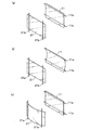
さらに、図7に示すように、第1光透過板11と第2光透過板21とを互いに直交させる方向に擬似円筒面を形成できるように配置しても構わない。そのため、図7(a)の状態から図7(b)の状態となるように、第1光透過板11を平板状態から擬似円筒面状態に湾曲させることで、例えば、パターンの投影像の縦方向のスケールを縮小(拡大)させる補正ができ、また、図7(b)の状態から図7(c)の状態となるように、第2光透過板21を平板状態から擬似円筒面状態に湾曲させることで、パターンの投影像の横方向のスケールを拡大(縮小)させることができるように設定できるものとなる。このとき、ガイドバー11a、11bおよびガイドバー21a,21bにそれぞれ各光透過板11,21を隔てて対面する位置に図示しないガイドバーを設定することで、擬似円筒面状態が凹面と凸面に変形することができるようになる。各光透過板11,21の両面位置にガイドバーを設置する場合には、シール枠体12c(22c)(図5参照)は、各光透過板11,21の板厚を両側から挟みこむように設けられると都合がよいものとなる。
Further, as shown in FIG. 7, the first
なお、両補正倍率光学系A1,A2は、それぞれ入射側凸レンズ4の入射面と、出射側凸レンズ7の出射面に各光透過板11,21を、密閉空間13,23を介して対面して配置する構成として説明したが、入射側凸レンズ4の出射面と、出射側凸レンズ7の入射面に対面して密閉空間13,23を介して各光透過板11,21を配置する構成としても構わない。
The correction magnification optical systems A1 and A2 face the
つぎに、投影露光装置1について説明する。なお、投影光学系Aに関する構成はすでに説明したので、その他の部分につて説明する。
図1に示すように、投影露光装置1は、光源3と、投影光学系Aと、ワークWを保持するワーク保持手段8と、マスクMとワークWのそれぞれのマークWm,Mmを撮像するCCDなどの撮像手段9と、この撮像手段9により撮像した両マークWm,Mmの位置情報から両マークWm,Mmのズレ量および、ワークWの伸縮量を演算して制御する制御手段17と、両マークWm,Mmを作業者が目視できるように表示するモニタ10とを主に備えている。
Next, the
As shown in FIG. 1, the
光源3は、所定波長の紫外線を含む光を照射するランプ2aと、このランプ2aから照射される光を集光して反射する楕円反射鏡2bとを有する光源部2と、この光源部2から照射された光を垂直方向から水平方向に反射する平面反射鏡2cと、この平面反射鏡2cから反射されてきた光の照度分布を均一化するためのフライアイレンズ2dとを備えている。
The light source 3 includes a
撮像手段9は、マスクMのマスクマークMmと、ワークWのワークマークWmとをハーフミラーなどを介して認識し、その認識した映像情報をモニタ10に出力すると共に、制御装置17に出力している。なお、この撮像手段9は、露光時には光路から退避して露光作業を行なうように図示しない移動手段に設けられている。
The imaging means 9 recognizes the mask mark Mm of the mask M and the work mark Wm of the workpiece W through a half mirror or the like, and outputs the recognized video information to the
制御手段17は、撮像手段9からの情報により、ワークWの伸縮状態を反映させて、両補正倍率光学系A1,A2のそれぞれの光透過板11,21の状態を変形させる密閉空間13,23の調整をしている変形手段16を制御すると共に、支持移動機構30の動作も制御し、かつ、ワーク保持テーブルの整合作業の動作についての制御を行なうものである。
The control means 17 reflects the expansion / contraction state of the workpiece W based on the information from the imaging means 9, and changes the state of the
この制御手段17は、撮像手段9から送られてきた映像情報をデジタル情報に変換する変換部17a、この変換部17aで変換されたデジタル情報を演算する演算部17bと、この演算部17bで演算された結果を比較する比較部17cと、この比較部17cの比較した結果に基づいて密閉空間の気圧の調整量と、支持移動機構30の移動量およびワーク保持手段8の整合移動量を決定する決定部17dと、各情報を記憶する記憶手段17eとを備えている。
The
変換部17aは、撮像手段9から送られてきた両マークWm,Mmの映像情報を多値化してデジタル情報に変換するものである。この変換部17aは、アナログ信号をデジタル信号に変化することができるものであれば、その構成を限定されるものではない。
また、演算部17bは、変換部17aで変換されたデジタル情報をあらかじめ設定された演算則に基づいて演算するものであり、各ワークマークWm(ここでは4箇所)の位置を示す位置情報を演算すると共に、各マスクマークMm(ここでは4箇所)の位置を示す位置情報とを演算している。この演算部17bは演算した結果を記憶手段17eに出力して記憶させている。
The
The
比較部17cは、記憶手段17eに記憶されているワークマークWmあるいはマスクマークMmの位置情報(あらかじめ記憶されている基準位置情報であっても良い)と、演算部17bにより演算されたそれぞれのマークWm,Mmの位置情報とを比較して、ワークマークWm間の距離およびマスクマークMmとワークマークMmとのズレ量を算出している。なお、ここでは、ワークマークWm間の距離が算出されることにより、ワークWの伸縮量も算出されることになる。
The
決定部17dは、比較部17cにより算出されたワークマークWm間の距離から、マスクMのパターンにおける投影像の補正倍率を、あらかじめ設定された演算式あるいはあらかじめ記憶手段17eに記憶させた演算テーブルに基づいて決定すると共に、密閉空間13,23の気圧の調整量を決定し、かつ、マスクマークMmとワークマークMmとのズレ量からワーク保持手段の整合量を決定するものである。さらに、この決定部17dは、算出されたワークマークWm間の距離から、支持移動機構30の移動量も決定するものである。
記憶手段17eは、各情報を記憶するためのものであり、ハードディスク、光ディスクなどの一般的にデータを記憶することができるものであれば、限定されるものではない。
Based on the distance between the work marks Wm calculated by the
The
ワーク保持手段8は、ワークWを設置面に対して垂直に保持する共に、ワークWのワークマークWmと、マスクMのマスクマークMmとの位置合わせ作業をする整合機構(図示せず)を備えている。
つぎに、投影露光装置1の作用を説明する。
投影露光装置1は、すでにマスクMが設定され、図示しないハンドラなどによりワークWがワーク保持手段8に保持されると、はじめに、撮像手段9によりマスクMのマスクマークMmと、ワークWのワークマークWmとを撮像位置まで移動して撮像する。撮像手段9により撮像された映像情報は、モニタ10に表示されると共に、制御手段17に出力される。
The workpiece holding means 8 includes an alignment mechanism (not shown) that holds the workpiece W perpendicular to the installation surface and performs an alignment operation between the workpiece mark Wm of the workpiece W and the mask mark Mm of the mask M. ing.
Next, the operation of the
In the
制御手段17では、変換部17a、演算部17b、比較分17cおよび決定部17dによりマスクMのマスクマークMmとワークWのワークマークWmとのズレ量から算出されたワークWのワーク保持手段8における整合移動量が決定され、ワーク保持手段8にその情報が出力されると共に、ワークWの伸縮量から両補正倍率光学系A1,A2の密閉空間13,23の気圧を調整する調整量が決定されその情報が変形手段16に出力される。そのため、ワーク保持手段8では、ワークWとマスクMの整合作業(アライメント作業)が行なわれ、再度、撮像手段9により撮像作業が行なわれ、両マークWm,Mmが許容範囲内であれば、整合作業は終了する。
In the control means 17, in the workpiece holding means 8 for the workpiece W calculated from the shift amount between the mask mark Mm of the mask M and the workpiece mark Wm of the workpiece W by the
また、変形手段16は、制御手段17からの制御により第1補正倍率光学系A1あるいは第2補正倍率光学系A2の密閉空間13,23のいずれかの気圧を調整して第1光透過板11あるいは第2光透過板21のいずれか一方を平板状態から擬似円筒面状態に湾曲させる。そして、光源3から紫外線を含む光を照射してマスクMを介して投影光として、投影光学系Aにより、ワークWに照射して露光作業を行なう。なお、ワークWの伸縮がなかった場合には、制御手段17は、変形手段16に密閉空間13,23の調整を行なわない信号を出すか、あるいは、あらかじめ決められた時間において、制御手段17からの命令がない場合には、密閉空間13,23の調整を行なわないように構成されている。
投影露光装置1では、露光作業が終了すると、図示しないハンドラなどによりワークWが搬出され、新たなワークがワーク保持手段に保持され、再び、整合作業からはじめられ、順次ワークWが露光される。
Further, the deforming means 16 adjusts the atmospheric pressure of the sealed
In the
なお、投影光学系Aの全体の倍率変更を行なうときには、制御手段17から移動量が支持移動機構30に出力されることにより支持移動機構30が制御され、両凸レンズ4,7を光軸方向に平行に移動させることで行なっている。そして、併せて両補正倍率光学系A1,A2の倍率補正を行なうことにより、マスクMのパターンにおける投影像の横方向(縦方向)におけるスケールの倍率補正についても適正に行なうことが可能となる。なお、投影光学系Aは、各光学エレメントが光学的に対称な配置になっているため、光軸方向に平行に移動させることにより、光路全体ではピントが合った状態で、かつ、全体の倍率を縮小拡大させる状態の投影光を提供することができるものである。したがって、投影露光装置1は、支持移動機構30により両凸レンズ4,7を移動させても光学的なバランスを保った状態で全体倍率の調整をすることができ、両凸レンズ4,7の移動に伴う歪曲の発生を極小に抑えられる。
When changing the overall magnification of the projection optical system A, the movement amount is output from the control means 17 to the
また、投影露光装置1における投影光学系Aは、入射側凸レンズから出射側凸レンズの光路に使用される各レンズを単レンズとしているため、接合レンズと異なり接合面の微妙な変化を一切考慮する必要がなく、投影光に対して高い精度を常に維持することが可能となる。
In addition, since the projection optical system A in the
さらに、投影光学系Aの両補正倍率光学系A1,A2では、密閉空間13,23に気圧を付加することで、擬似円筒面状態を形成するものについて説明したが、密閉空間13,23を負圧にすることで、擬似円筒面状態を形成するものとしてもよい。すなわち、ガイドバー11a,11b(21a,21b)に対面する位置に、さらに、図示しないガイドバーをそれぞれ配置(このとき枠本体12a,22aはガイドバーを支持する突片を形成したことになる)し、シール枠体12c(22c)の上部あるいはシール枠体12c(22c)から外れた位置において第1光透過板11(第2光透過板21)をガイドする構成としている。したがって、密閉空間13,23を加圧すると、第1または第2光透過板11,21を凸状な擬似円筒面状態に湾曲させ、また、密閉空間13,23を負圧にすることで、第1または第2光透過板11,21を凹状な擬似円筒面状態に湾曲させることができるものとなる。なお、ガイドバーがない構成であっても、シール枠体12c,22cのみで、密閉空間13,23の気圧を加圧あるいは負圧にすることで、両光透過板11,21を擬似円筒面状態に湾曲して使用するものであっても構わない。
Furthermore, in the two correction magnification optical systems A1 and A2 of the projection optical system A, a description has been given of forming a pseudo-cylindrical surface state by applying atmospheric pressure to the sealed
また、ここでは、両凸レンズ4,7の中央から下方に渡って各光透過板11,21を対面した状態として説明したが、両凸レンズ4,7の全面に渡って対面するように各光透過板11,21およびその他の構成を設定しても構わないものである。
さらに、両光透過板11,21を擬似円筒面状態に湾曲し易くするために、ガイドバー11a,11b(21a,21b)を用いた構成として説明したが、このガイドバー11a,11b(21a,21b)の構成に限定されるものではなく、例えば、シール枠体12c(22c)の垂直部分と水平部分の伸び率が異なる構成とするものを用いるなど、両光透過板11,21が擬似円筒面状態に湾曲しやすい構成となるものであれば構わない。
In addition, here, the description has been made assuming that the
Furthermore, in order to make it easy to bend both the
A 投影光学系
A1 第1補正倍率光学系
A2 第2補正倍率光学系
1 投影露光装置
2 光源部
2a ランプ
2b 楕円反射鏡
2c 平面反射鏡
2d フライアイレンズ
3 光源
4 入射側凸レンズ
4a 第1反射面
4b 第2反射面
5 反射体
6 反射補正光学系
6a 凸レンズ
6b 平凸レンズ
6c 凹レンズ
6d 反射ミラー
7 出射側凸レンズ
8 基板保持手段
9 撮像手段
11 第1光透過板
11a ガイドバー
11b ガイドバー
12 第1保持手段
12a,22a 枠本体
12b,22b 補助フレーム
12c,22c シール枠体
12d,22d 挟持枠体
12e,22e レンズ挟持枠体
13,23 密閉空間
14 接続管
15 調整手段
16 変形手段(第1変形手段、第2変形手段)
21 第2光透過板
22 第2保持手段
A projection optical system A1 first correction magnification optical system A2 second correction magnification
21 Second
Claims (11)
前記投影光の方向を変える第1反射面および第2反射面を所定角度に設けた反射体と、
この反射体に対峙して配置され、前記第1反射面で反射した投影光を前記第2反射面に反射させる反射補正光学系と、
この反射補正光学系の中心軸に対して対称となる一方の位置で、かつ、当該光学系が設置される設置面に対して垂直に配置され、前記第1反射面に前記投影光を透過して送る位置に設けた入射側凸レンズと、
前記反射補正光学系の中心軸に対して対称となる他方の位置で、かつ、当該光学系が設置される設置面に対して垂直に配置され、前記第2反射面からの前記投影光を透過する位置に設けた出射側凸レンズと、
前記投影光の前記入射側凸レンズに対面して設けられた第1光透過板を擬似円筒面状態に変形されることで、前記パターンの投影像の倍率補正を行なう第1補正倍率光学系と、
前記投影光の前記出射側凸レンズに対面して設けられた第2光透過板を擬似円筒面状態に変形されることで、前記パターンの投影像の倍率補正を行なう第2補正倍率光学系と、を備えることを特徴とする投影光学系。 In a projection optical system used when light including ultraviolet rays emitted from a light source passes through a mask on which an exposure pattern is drawn and is projected as projection light onto an exposure area of a substrate to be processed.
A reflector having a first reflecting surface and a second reflecting surface that change the direction of the projection light at a predetermined angle;
A reflection correcting optical system that is arranged opposite to the reflector and reflects the projection light reflected by the first reflecting surface to the second reflecting surface;
One of the positions that is symmetrical with respect to the central axis of the reflection correction optical system, and is disposed perpendicular to the installation surface on which the optical system is installed, and transmits the projection light to the first reflection surface. The incident side convex lens provided at the position
The other position that is symmetric with respect to the central axis of the reflection correction optical system and is perpendicular to the installation surface on which the optical system is installed, and transmits the projection light from the second reflection surface An exit-side convex lens provided at a position to
A first correction magnification optical system that performs magnification correction of the projected image of the pattern by deforming a first light transmission plate provided facing the incident-side convex lens of the projection light into a pseudo-cylindrical surface state;
A second correction magnification optical system for correcting the magnification of the projected image of the pattern by deforming the second light transmission plate provided facing the exit-side convex lens of the projection light into a pseudo-cylindrical surface state; A projection optical system comprising:
前記第2補正倍率光学系は、前記出射側凸レンズに対面して配置された前記第2光透過板と、この第2光透過板を、シール枠体を介して保持する第2保持手段とを備え、
前記第1保持手段、前記シール枠体、第1光透過板ならびに前記入射側凸レンズで囲繞される密閉空間、または、前記第2保持手段、前記シール枠体、第2光透過板ならびに前記出射側凸レンズで囲繞される密閉空間のそれぞれの気圧を調整して前記第1光透過板または前記第2光透過板を、前記シール枠体のそれぞれを介して平板状態から擬似円筒面状態に変形させる変形手段を備えることを特徴とする請求項1に記載の投影光学系。 The first correction magnification optical system includes the first light transmission plate disposed to face the incident-side convex lens, and first holding means for holding the first light transmission plate via a seal frame. Prepared,
The second correction magnification optical system includes the second light transmission plate disposed to face the exit-side convex lens, and second holding means for holding the second light transmission plate via a seal frame. Prepared,
The first holding means, the seal frame, the first light transmission plate and the sealed space surrounded by the incident side convex lens, or the second holding means, the seal frame, the second light transmission plate, and the emission side Deformation in which the first light transmission plate or the second light transmission plate is deformed from a flat plate state to a quasi-cylindrical surface state through each of the seal frames by adjusting the pressure of each sealed space surrounded by the convex lens. The projection optical system according to claim 1, further comprising means.
前記第1保持手段、前記シール枠体、前記第1光透過板ならびに前記入射側凸レンズで囲繞される密閉空間の気圧を調整して前記第1光透過板を、前記シール枠体を介して平板状態から擬似円筒面状態に変形させる第1変形手段とを備え、
前記第2補正倍率光学系は、前記出射側凸レンズに対面して配置された前記第2光透過板と、この第2光透過板を、シール枠体を介して保持する第2保持手段とを備え、
前記第2保持手段、前記シール枠体、前記第2光透過板ならびに前記出射側凸レンズで囲繞される密閉空間の気圧を調整して前記第2光透過板を、前記シール枠体を介して平板状態から擬似円筒面状態に変形させる第2変形手段と、を備えることを特徴とする請求項1に記載の投影光学系。 The first correction magnification optical system includes the first light transmission plate disposed to face the incident-side convex lens, and first holding means for holding the first light transmission plate via a seal frame. Prepared,
The first light transmitting plate is adjusted to a flat plate through the seal frame by adjusting the air pressure in the sealed space surrounded by the first holding means, the seal frame, the first light transmitting plate, and the incident side convex lens. First deformation means for deforming from a state to a pseudo-cylindrical surface state,
The second correction magnification optical system includes the second light transmission plate disposed to face the exit-side convex lens, and second holding means for holding the second light transmission plate via a seal frame. Prepared,
The second light transmitting plate is adjusted to a flat plate through the seal frame by adjusting the air pressure in the sealed space surrounded by the second holding means, the seal frame, the second light transmitting plate, and the exit convex lens. The projection optical system according to claim 1, further comprising: a second deforming unit configured to deform from a state to a pseudo cylindrical surface state.
前記第2保持手段は、前記投影光を通過させる開口窓を有し、前記出射側凸レンズに沿って配置される枠本体と、この枠本体の開口窓に沿って設置され前記第2光透過板を設ける前記シール枠体と、このシール枠体および前記第2光透過板を挟持すると共に、前記第2光透過板に対応して開口を有する挟持枠体と、前記第2光透過板を擬似円筒面状態に湾曲させる方向にガイドし、前記光透過板の湾曲頂部に対して対称となる位置で前記挟持枠体と前記光透過板の間に設けられたガイドバーと、を備えることを特徴とする請求項2または請求項3に記載の投影光学系。 The first holding means includes an opening window that allows the projection light to pass therethrough, a frame main body disposed along the incident-side convex lens, and the first light transmitting plate installed along the opening window of the frame main body. The seal frame body, the sandwiching frame body sandwiching the seal frame body and the first light transmission plate and having an opening corresponding to the first light transmission plate, and the first light transmission plate being simulated. A guide bar provided between the sandwiching frame body and the light transmission plate at a position that is symmetrical with respect to the curved top portion of the light transmission plate, guiding in a direction to be curved into a cylindrical surface state,
The second holding means includes an opening window that allows the projection light to pass therethrough, a frame main body disposed along the exit-side convex lens, and the second light transmitting plate that is installed along the opening window of the frame main body. The seal frame body, the sandwiching frame body sandwiching the seal frame body and the second light transmission plate and having an opening corresponding to the second light transmission plate, and the second light transmission plate being simulated. A guide bar provided between the sandwiching frame body and the light transmission plate at a position that is symmetric with respect to the curved top portion of the light transmission plate, and is guided in a direction to be curved in a cylindrical surface state. The projection optical system according to claim 2 or claim 3.
1<{(d/D)×100}<10 式(1)
0.01<(ω2×d)<2.5 式(2)
を満足することを特徴とする請求項1から請求項4のいずれか一項に記載の投影光学系。 The first light transmission plate and the second light transmission plate are synthetic quartz glass plates with infinite curvature, the long side of the synthetic quartz glass plate is D, the center thickness is d, and the projection When the maximum chief ray tilt angle in the optical system is ω, the conditions shown by the following equations (1) and (2):
1 <{(d / D) × 100} <10 Formula (1)
0.01 <(ω 2 × d) <2.5 Formula (2)
The projection optical system according to any one of claims 1 to 4, wherein:
前記被処理基板と前記マスクにあらかじめ形成されているそれぞれの整合マークを撮像する撮像手段と、前記被処理基板と前記マスクの間に設けられた投影光学系と、この投影光学系の入射側および出射側にそれぞれ設置された、前記マスクにおけるパターンの投影像の倍率を補正する第1補正倍率光学系および第2補正倍率光学系と、前記撮像手段により撮像した前記各マークの映像情報に基づいて、前記補正倍率光学系のそれぞれについて前記パターンの投影像の倍率補正を行なうように制御する制御手段と、を備えることを特徴とする投影露光装置。 In a projection exposure apparatus for irradiating light including ultraviolet rays emitted from a light source through a mask on which an exposure pattern is drawn and projecting light onto an exposure region of a substrate to be processed that forms the pattern,
Imaging means for imaging respective alignment marks formed in advance on the substrate to be processed and the mask, a projection optical system provided between the substrate to be processed and the mask, an incident side of the projection optical system, and Based on the first correction magnification optical system and the second correction magnification optical system, which are respectively installed on the exit side, for correcting the magnification of the projected image of the pattern on the mask, and the image information of each mark imaged by the imaging means And a control means for controlling each of the correction magnification optical systems so as to perform magnification correction of the projected image of the pattern.
前記第2補正倍率光学系は、前記投影光学系の出射側凸レンズに対面して密閉空間を介して設けた第2光透過板を備え、
前記密閉空間のそれぞれの気圧を調整して、前記第1光透過板または前記第2光透過板を平板状態から擬似円筒面状態に変形させる変形手段を備え、
前記制御手段は、前記映像情報に基づいて、前記変形手段を制御することを特徴とする請求項10に記載の投影露光装置。 The first correction magnification optical system includes a first light transmission plate provided through a sealed space facing the incident side convex lens of the projection optical system,
The second correction magnification optical system includes a second light transmission plate that is provided through a sealed space so as to face the exit-side convex lens of the projection optical system,
Adjusting each atmospheric pressure of the sealed space, comprising a deformation means for deforming the first light transmission plate or the second light transmission plate from a flat plate state to a pseudo cylindrical surface state,
The projection exposure apparatus according to claim 10, wherein the control unit controls the deformation unit based on the video information.
Priority Applications (1)
| Application Number | Priority Date | Filing Date | Title |
|---|---|---|---|
| JP2004107232A JP4195674B2 (en) | 2004-03-31 | 2004-03-31 | Projection optical system and projection exposure apparatus |
Applications Claiming Priority (1)
| Application Number | Priority Date | Filing Date | Title |
|---|---|---|---|
| JP2004107232A JP4195674B2 (en) | 2004-03-31 | 2004-03-31 | Projection optical system and projection exposure apparatus |
Publications (3)
| Publication Number | Publication Date |
|---|---|
| JP2005292450A true JP2005292450A (en) | 2005-10-20 |
| JP2005292450A5 JP2005292450A5 (en) | 2006-02-09 |
| JP4195674B2 JP4195674B2 (en) | 2008-12-10 |
Family
ID=35325439
Family Applications (1)
| Application Number | Title | Priority Date | Filing Date |
|---|---|---|---|
| JP2004107232A Expired - Lifetime JP4195674B2 (en) | 2004-03-31 | 2004-03-31 | Projection optical system and projection exposure apparatus |
Country Status (1)
| Country | Link |
|---|---|
| JP (1) | JP4195674B2 (en) |
Cited By (4)
| Publication number | Priority date | Publication date | Assignee | Title |
|---|---|---|---|---|
| JP2009124139A (en) * | 2007-11-09 | 2009-06-04 | Asml Netherlands Bv | Device manufacturing method, lithographic apparatus, and computer program product |
| JP2011082311A (en) * | 2009-10-06 | 2011-04-21 | Canon Inc | Optical projection system, aligner, and method of manufacturing device |
| WO2012043130A1 (en) * | 2010-09-30 | 2012-04-05 | 株式会社ニコン | Projection optical assembly, projection optical assembly adjustment method, exposure device, exposure method, and device manufacturing method |
| JP2013511843A (en) * | 2009-11-20 | 2013-04-04 | コーニング インコーポレイテッド | Magnification control of lithographic imaging system |
Citations (6)
| Publication number | Priority date | Publication date | Assignee | Title |
|---|---|---|---|---|
| JPS59144127A (en) * | 1983-02-07 | 1984-08-18 | Canon Inc | Optical apparatus with adjustment of image |
| JPH0883744A (en) * | 1994-09-09 | 1996-03-26 | Nikon Corp | Scanning exposure device |
| JPH10509561A (en) * | 1994-10-28 | 1998-09-14 | ウルトラテック ステッパー, インコーポレイテッド | Beam splitter and optical variable magnification method and system in single-fold optical system |
| JPH11502941A (en) * | 1995-03-22 | 1999-03-09 | イーテック システムズ,インコーポレーテッド | Magnification correction for small field scanning |
| JPH11502942A (en) * | 1995-03-22 | 1999-03-09 | イーテック システムズ,インコーポレーテッド | Scanning lithography system with opposing movement |
| JPH11503529A (en) * | 1995-03-22 | 1999-03-26 | イーテック システムズ,インコーポレーテッド | Scanning lithography system with folded pass wine-dyson optics |
-
2004
- 2004-03-31 JP JP2004107232A patent/JP4195674B2/en not_active Expired - Lifetime
Patent Citations (6)
| Publication number | Priority date | Publication date | Assignee | Title |
|---|---|---|---|---|
| JPS59144127A (en) * | 1983-02-07 | 1984-08-18 | Canon Inc | Optical apparatus with adjustment of image |
| JPH0883744A (en) * | 1994-09-09 | 1996-03-26 | Nikon Corp | Scanning exposure device |
| JPH10509561A (en) * | 1994-10-28 | 1998-09-14 | ウルトラテック ステッパー, インコーポレイテッド | Beam splitter and optical variable magnification method and system in single-fold optical system |
| JPH11502941A (en) * | 1995-03-22 | 1999-03-09 | イーテック システムズ,インコーポレーテッド | Magnification correction for small field scanning |
| JPH11502942A (en) * | 1995-03-22 | 1999-03-09 | イーテック システムズ,インコーポレーテッド | Scanning lithography system with opposing movement |
| JPH11503529A (en) * | 1995-03-22 | 1999-03-26 | イーテック システムズ,インコーポレーテッド | Scanning lithography system with folded pass wine-dyson optics |
Cited By (7)
| Publication number | Priority date | Publication date | Assignee | Title |
|---|---|---|---|---|
| JP2009124139A (en) * | 2007-11-09 | 2009-06-04 | Asml Netherlands Bv | Device manufacturing method, lithographic apparatus, and computer program product |
| JP2011082311A (en) * | 2009-10-06 | 2011-04-21 | Canon Inc | Optical projection system, aligner, and method of manufacturing device |
| KR101476871B1 (en) * | 2009-10-06 | 2014-12-26 | 캐논 가부시끼가이샤 | Projection optical system, exposure apparatus and method of manufacturing a device |
| JP2013511843A (en) * | 2009-11-20 | 2013-04-04 | コーニング インコーポレイテッド | Magnification control of lithographic imaging system |
| US8922750B2 (en) | 2009-11-20 | 2014-12-30 | Corning Incorporated | Magnification control for lithographic imaging system |
| JP2015180945A (en) * | 2009-11-20 | 2015-10-15 | コーニング インコーポレイテッド | Magnification control for lithographic imaging system |
| WO2012043130A1 (en) * | 2010-09-30 | 2012-04-05 | 株式会社ニコン | Projection optical assembly, projection optical assembly adjustment method, exposure device, exposure method, and device manufacturing method |
Also Published As
| Publication number | Publication date |
|---|---|
| JP4195674B2 (en) | 2008-12-10 |
Similar Documents
| Publication | Publication Date | Title |
|---|---|---|
| US10067324B2 (en) | Projection device and projection system | |
| TW503466B (en) | Reflection/refraction optical system and projection exposure apparatus comprising the optical system, exposure method and manufacturing method of micro-device | |
| US7130018B2 (en) | Catoptric projection optical system, exposure apparatus and device fabrication method | |
| JP6326717B2 (en) | Projection optical system and image display device | |
| JP5071382B2 (en) | Scanning exposure apparatus and microdevice manufacturing method | |
| US20070296936A1 (en) | Exposure Apparatus, Exposure Method, and Producing Method of Microdevice | |
| KR102438345B1 (en) | Image-forming optical system, exposure apparatus, and device producing method | |
| TW201905535A (en) | Magnification compensation and/or beam steering in an optical system | |
| JPWO2001065296A1 (en) | Catadioptric optical system and projection exposure apparatus equipped with said optical system | |
| WO2001059502A1 (en) | Reflection/refraction optical system | |
| TW200305786A (en) | Projection system, exposure device and espousing method | |
| WO1999027570A1 (en) | Projection exposure system | |
| JP5595001B2 (en) | Projection optical system, exposure apparatus, and device manufacturing method | |
| JPWO2007091463A1 (en) | Catadioptric imaging optical system, exposure apparatus, and device manufacturing method | |
| KR100659245B1 (en) | Optical projection system | |
| WO2015041335A1 (en) | Projection optical system, method for adjusting projection optical system, exposure apparatus, exposure method, and device production method | |
| JP2005051147A (en) | Exposure method and exposure apparatus | |
| US9703085B2 (en) | Catadioptric imaging systems for digital scanner | |
| US9411246B2 (en) | Full-field maskless lithography projection optics | |
| US20090161087A1 (en) | Projection optical system, aligner, and method for fabricating device | |
| JP2005340605A (en) | Exposure apparatus and adjustment method thereof | |
| JP4195674B2 (en) | Projection optical system and projection exposure apparatus | |
| JP2005183736A (en) | Exposure method and apparatus, and device manufacturing method | |
| JP2006184709A (en) | Imaging optical system, exposure apparatus, and microdevice manufacturing method | |
| JP5360529B2 (en) | Projection optical system, exposure apparatus, and device manufacturing method |
Legal Events
| Date | Code | Title | Description |
|---|---|---|---|
| A521 | Request for written amendment filed |
Free format text: JAPANESE INTERMEDIATE CODE: A523 Effective date: 20051219 |
|
| A131 | Notification of reasons for refusal |
Free format text: JAPANESE INTERMEDIATE CODE: A131 Effective date: 20071017 |
|
| A521 | Request for written amendment filed |
Free format text: JAPANESE INTERMEDIATE CODE: A523 Effective date: 20071213 |
|
| A02 | Decision of refusal |
Free format text: JAPANESE INTERMEDIATE CODE: A02 Effective date: 20080415 |
|
| A521 | Request for written amendment filed |
Free format text: JAPANESE INTERMEDIATE CODE: A821 Effective date: 20080516 |
|
| A521 | Request for written amendment filed |
Free format text: JAPANESE INTERMEDIATE CODE: A523 Effective date: 20080616 |
|
| A521 | Request for written amendment filed |
Free format text: JAPANESE INTERMEDIATE CODE: A523 Effective date: 20080704 |
|
| A911 | Transfer to examiner for re-examination before appeal (zenchi) |
Free format text: JAPANESE INTERMEDIATE CODE: A911 Effective date: 20080806 |
|
| TRDD | Decision of grant or rejection written | ||
| A01 | Written decision to grant a patent or to grant a registration (utility model) |
Free format text: JAPANESE INTERMEDIATE CODE: A01 Effective date: 20080916 |
|
| A01 | Written decision to grant a patent or to grant a registration (utility model) |
Free format text: JAPANESE INTERMEDIATE CODE: A01 |
|
| A61 | First payment of annual fees (during grant procedure) |
Free format text: JAPANESE INTERMEDIATE CODE: A61 Effective date: 20080926 |
|
| R150 | Certificate of patent or registration of utility model |
Ref document number: 4195674 Country of ref document: JP Free format text: JAPANESE INTERMEDIATE CODE: R150 Free format text: JAPANESE INTERMEDIATE CODE: R150 |
|
| FPAY | Renewal fee payment (event date is renewal date of database) |
Free format text: PAYMENT UNTIL: 20111003 Year of fee payment: 3 |
|
| FPAY | Renewal fee payment (event date is renewal date of database) |
Free format text: PAYMENT UNTIL: 20111003 Year of fee payment: 3 |
|
| FPAY | Renewal fee payment (event date is renewal date of database) |
Free format text: PAYMENT UNTIL: 20111003 Year of fee payment: 3 |
|
| FPAY | Renewal fee payment (event date is renewal date of database) |
Free format text: PAYMENT UNTIL: 20111003 Year of fee payment: 3 |
|
| FPAY | Renewal fee payment (event date is renewal date of database) |
Free format text: PAYMENT UNTIL: 20121003 Year of fee payment: 4 |
|
| R250 | Receipt of annual fees |
Free format text: JAPANESE INTERMEDIATE CODE: R250 |
|
| FPAY | Renewal fee payment (event date is renewal date of database) |
Free format text: PAYMENT UNTIL: 20121003 Year of fee payment: 4 |
|
| FPAY | Renewal fee payment (event date is renewal date of database) |
Free format text: PAYMENT UNTIL: 20131003 Year of fee payment: 5 |
|
| R250 | Receipt of annual fees |
Free format text: JAPANESE INTERMEDIATE CODE: R250 |
|
| R250 | Receipt of annual fees |
Free format text: JAPANESE INTERMEDIATE CODE: R250 |
|
| R250 | Receipt of annual fees |
Free format text: JAPANESE INTERMEDIATE CODE: R250 |
|
| R250 | Receipt of annual fees |
Free format text: JAPANESE INTERMEDIATE CODE: R250 |
|
| R250 | Receipt of annual fees |
Free format text: JAPANESE INTERMEDIATE CODE: R250 |
|
| R250 | Receipt of annual fees |
Free format text: JAPANESE INTERMEDIATE CODE: R250 |
|
| R250 | Receipt of annual fees |
Free format text: JAPANESE INTERMEDIATE CODE: R250 |
|
| R250 | Receipt of annual fees |
Free format text: JAPANESE INTERMEDIATE CODE: R250 |
|
| R250 | Receipt of annual fees |
Free format text: JAPANESE INTERMEDIATE CODE: R250 |
|
| R250 | Receipt of annual fees |
Free format text: JAPANESE INTERMEDIATE CODE: R250 |
|
| R250 | Receipt of annual fees |
Free format text: JAPANESE INTERMEDIATE CODE: R250 |
|
| R250 | Receipt of annual fees |
Free format text: JAPANESE INTERMEDIATE CODE: R250 |
|
| EXPY | Cancellation because of completion of term |