JP2005292445A - Lens control system - Google Patents
Lens control system Download PDFInfo
- Publication number
- JP2005292445A JP2005292445A JP2004107177A JP2004107177A JP2005292445A JP 2005292445 A JP2005292445 A JP 2005292445A JP 2004107177 A JP2004107177 A JP 2004107177A JP 2004107177 A JP2004107177 A JP 2004107177A JP 2005292445 A JP2005292445 A JP 2005292445A
- Authority
- JP
- Japan
- Prior art keywords
- clutch
- zoom
- lens
- motor
- electric operation
- Prior art date
- Legal status (The legal status is an assumption and is not a legal conclusion. Google has not performed a legal analysis and makes no representation as to the accuracy of the status listed.)
- Pending
Links
- 238000000034 method Methods 0.000 description 12
- 238000006073 displacement reaction Methods 0.000 description 5
- 230000003287 optical effect Effects 0.000 description 3
- 238000010586 diagram Methods 0.000 description 2
- 210000003811 finger Anatomy 0.000 description 2
- 230000005540 biological transmission Effects 0.000 description 1
- 230000007935 neutral effect Effects 0.000 description 1
- 210000003813 thumb Anatomy 0.000 description 1
Images

Landscapes
- Lens Barrels (AREA)
- Studio Devices (AREA)
Abstract
Description
本発明はレンズ制御システムに係り、特に撮影レンズのレンズ操作を手動と電動に切り替えるクラッチを備えたレンズ制御システムに関する。 The present invention relates to a lens control system, and more particularly to a lens control system including a clutch that switches a lens operation of a photographing lens between manual and electric.
放送用テレビカメラなどで使用される撮影レンズにおいて、鏡胴にフォーカスリング、ズームリング、アイリスリング等の操作リングが回動可能に設けられ、それらの操作リングの回動操作によってフォーカス操作、ズーム操作、アイリス操作というようなレンズ操作を行うことができる携帯型のENGレンズが知られている。 In photographic lenses used in broadcast TV cameras, etc., operation rings such as a focus ring, zoom ring, and iris ring can be rotated on the lens barrel. A portable ENG lens capable of performing lens operation such as iris operation is known.
ENGレンズは、鏡胴側部に駆動ユニットが標準的に装着されており、その駆動ユニットには各操作リングを回動するモータが内蔵されている。モータはクラッチ機構(クラッチ)を介して操作リングに連結されるのが一般的で、クラッチをオン(連結)することによってモータと操作リングとの間が連結され、モータの動力によって操作リングが回動するようになっている。駆動ユニットを覆うケースには例えばズーム操作用のズームシーソーレバーが設けられており、そのズームシーソーレバーを操作すると、駆動ユニット内のモータが回動し、モータに連結されたズームリングが回動する。また、駆動ユニットには、外部のコントローラなどからの外部入力に従ってモータを駆動し、操作リングを電動で回動操作する機能を備えたものもある。 The ENG lens is equipped with a drive unit as standard on the side of the lens barrel, and the drive unit incorporates a motor that rotates each operation ring. The motor is generally connected to the operation ring via a clutch mechanism (clutch). When the clutch is turned on (connected), the motor and the operation ring are connected, and the operation ring is rotated by the power of the motor. It comes to move. The case that covers the drive unit is provided with a zoom seesaw lever for zoom operation, for example. When the zoom seesaw lever is operated, the motor in the drive unit rotates and the zoom ring connected to the motor rotates. . Some drive units have a function of driving a motor in accordance with an external input from an external controller or the like and electrically rotating an operation ring.
一方、クラッチをオフ(切断)するとモータと操作リングとの間の連結が切断され、操作リングが自由に回動する状態となるため、クラッチをオフすることによって操作リングを直接手動で回動操作することができるようになっている。 On the other hand, when the clutch is turned off (disconnected), the connection between the motor and the operation ring is disconnected, and the operation ring is freely rotated. Therefore, the operation ring is directly rotated manually by turning off the clutch. Can be done.
このような駆動ユニットにおいて、クラッチのオン/オフの切替操作を行うことなく、操作リングの回動操作を電動と手動のいずれでも行えるようにしたクラッチ自動切替機能を備えたものが提案されている(例えば、特許文献1参照)。これによれば、クラッチのオン/オフが電動で切り替わると共に、電動の操作を行っていない場合、即ち、モータを駆動するための制御信号が出力されていない場合にはクラッチがオフされ、操作リングを手動で回動操作することができ、電動の操作を行っている場合、即ち、モータを駆動する制御信号が出力されている場合にはクラッチがオンされ、操作リングを電動で回動操作することができるようになっている。
ところで、上述のようなクラッチ自動切替機能を備えた駆動ユニットにおいて、例えばズームシーソーレバーを操作すると、その操作量に応じた速度でズームリング(モータ)が回動する。このように電動の操作によってズームリングの速度制御が行われる場合には、電動の操作を停止すれば確実にクラッチがオフの状態に保持される。しかしながら、コントローラを駆動ユニットに接続し、そのコントローラでの電動の操作によりズームリングを位置制御しようとした場合には次のような問題があった。 By the way, in the drive unit having the clutch automatic switching function as described above, for example, when the zoom seesaw lever is operated, the zoom ring (motor) rotates at a speed corresponding to the operation amount. In this way, when the speed control of the zoom ring is performed by electric operation, the clutch is surely held in the off state by stopping the electric operation. However, when a controller is connected to the drive unit and position control of the zoom ring is performed by an electric operation with the controller, there are the following problems.
ズームリングを位置制御する場合、ズームリングの現在位置を位置センサで検出し、その現在位置を示す値(現在値)と、コントローラでの電動の操作によって指定される目標位置を示す目標値との差が0となるようにその差に応じた速度でズームリングが回動する。コントローラでの電動の操作を停止し、ズームリングが目標位置に到達すると、モータの駆動が停止する。従って、速度制御の場合と同様に位置制御の場合でも電動の操作を停止するとクラッチ自動切替機能によりクラッチが自動的にオフされる。しかしながら、このような状態であっても、位置制御の場合にはその制御系の特性や、位置センサの出力信号の変動(ノイズ等)によって目標位置とズームリングの現在位置とに差が生じるおそれがあり、モータを駆動する制御信号が断続的に出力される可能性がある。そのため、クラッチが連続的にオン/オフを繰り返し、クラッチの磨耗やクラッチを駆動するため消費電力の増加を招くというおそれがあった。 When controlling the position of the zoom ring, the current position of the zoom ring is detected by a position sensor, and a value indicating the current position (current value) and a target value indicating a target position specified by an electric operation by the controller The zoom ring rotates at a speed corresponding to the difference so that the difference becomes zero. When the electric operation at the controller is stopped and the zoom ring reaches the target position, the driving of the motor is stopped. Therefore, as in the case of speed control, even in the case of position control, when the electric operation is stopped, the clutch is automatically turned off by the clutch automatic switching function. However, even in such a state, in the case of position control, there may be a difference between the target position and the current position of the zoom ring due to the characteristics of the control system and fluctuation (noise, etc.) of the output signal of the position sensor. There is a possibility that a control signal for driving the motor is intermittently output. For this reason, the clutch is continuously turned on and off, and there is a possibility that the clutch wears out and the power consumption increases because the clutch is driven.
本発明はこのような事情に鑑みてなされたもので、クラッチ自動切替機能を有するレンズ制御システムにおいて、速度制御や位置制御などの制御方式の相違によってクラッチが不安定な動作となるのを未然に防止し、コントローラの種類やシステムに関係なく常に最適なレンズ制御を行うことができるレンズ制御システムを提供することを目的とする。 The present invention has been made in view of such circumstances, and in a lens control system having an automatic clutch switching function, it is possible to prevent the clutch from becoming unstable due to a difference in control methods such as speed control and position control. It is an object of the present invention to provide a lens control system capable of preventing and always performing optimum lens control regardless of the type or system of the controller.
前記目的を達成するために、請求項1に記載のレンズ制御システムは、撮影レンズの可動のレンズ群とモータとの間を連結又は切断するクラッチ機構と、前記レンズ群を電動により操作するための電動操作手段と、前記電動操作手段による電動の操作に従って前記モータを駆動するモータ制御手段と、手動の操作による手動力により前記レンズ群を駆動する手動操作手段と、前記電動操作手段により電動の操作が行われると、前記クラッチ機構をオンにして前記レンズ群と前記モータとの間を連結し、前記電動操作手段による電動の操作が停止すると前記クラッチ機構をオフして前記レンズ群と前記モータとの間を切断するクラッチ自動切替手段とを備えたレンズ制御システムにおいて、前記クラッチ自動切替手段による前記クラッチ機構のオン/オフの切替えを有効又は無効に切り替える切替手段を備えたことを特徴としている。本発明によれば、クラッチ自動切替機能を無効にすることができるため、クラッチが不安定な動作となる場合には未然にそれを防止することができ、クラッチの不要な磨耗や消費電力の増加を防止することができる。
In order to achieve the above object, a lens control system according to
請求項2に記載のレンズ制御システムは、請求項1に記載の発明において、クラッチ自動切替機能のオン/オフの選択を入力する入力手段を備え、前記切替手段は、前記入力手段により入力された選択に基づいて前記クラッチ自動切替手段による前記クラッチ機構のオン/オフの切替えを有効又は無効に切り替えることを特徴としている。本発明では、ユーザの判断によりクラッチ自動切替機能を有効とするか無効とするかを選択することができる。 According to a second aspect of the present invention, the lens control system according to the first aspect of the present invention includes input means for inputting selection of ON / OFF of the automatic clutch switching function, and the switching means is input by the input means. Based on the selection, on / off switching of the clutch mechanism by the automatic clutch switching means is switched between valid and invalid. In the present invention, it is possible to select whether to enable or disable the automatic clutch switching function according to the user's judgment.
請求項3に記載のレンズ制御システムは、請求項1に記載の発明において、前記切替手段は、前記電動操作手段による電動の操作が目標速度を指定する速度制御の操作の場合には前記クラッチ自動切替手段による前記クラッチ機構のオン/オフの切替えを有効にし、前記電動操作手段による電動の操作が目標位置を指定する位置制御の操作の場合には前記クラッチ自動切替手段による前記クラッチ機構のオン/オフの切替えを無効にすることを特徴としている。本発明は、クラッチ自動切替機能を自動的に有効又は無効に切り替えるようにしたもので、クラッチが不安定動作となる可能性がある位置制御の場合にクラッチ自動切替機能を無効にする。 According to a third aspect of the present invention, in the lens control system according to the first aspect, the switching unit may be configured to perform the automatic clutch operation when the electric operation by the electric operation unit is a speed control operation that specifies a target speed. When switching of the clutch mechanism by the switching means is made effective, and the electric operation by the electric operation means is a position control operation for designating a target position, the clutch mechanism is turned on / off by the clutch automatic switching means. It is characterized by invalidating off switching. According to the present invention, the automatic clutch switching function is automatically switched between valid and invalid, and the automatic clutch switching function is invalidated in the case of position control in which the clutch may become unstable.
本発明に係るレンズ制御システムによれば、速度制御や位置制御などの制御方式の相違によってクラッチ自動切替機能でのクラッチの動作が不安定になるのを未然に防止することができ、コントローラの種類やシステムに関係なく常に最適なレンズ制御を行うことができる。 According to the lens control system of the present invention, it is possible to prevent the operation of the clutch in the clutch automatic switching function from becoming unstable due to a difference in control methods such as speed control and position control. Optimal lens control can always be performed regardless of the system.
以下、添付図面に従って本発明に係るレンズ制御システムの好ましい実施の形態について詳説する。 Hereinafter, a preferred embodiment of a lens control system according to the present invention will be described in detail with reference to the accompanying drawings.
図1は、本発明が適用されるレンズ装置の外観を示した平面図である。同図に示すレンズ装置10は、テレビ放送用のENGカメラ等に交換可能に装着されるENGレンズであり、インナーフォーカス式ズームレンズである。尚、以下、レンズ装置10をENGレンズ10という。
FIG. 1 is a plan view showing the external appearance of a lens apparatus to which the present invention is applied. A
ENGレンズ10は、主に、レンズ鏡胴12とその内部の光学部品、及び、レンズ鏡胴12の側部に装着される駆動ユニット14とから構成されている。
The ENG
レンズ鏡胴12の後端にはマウントが設けられており、これによりカメラ本体に着脱可能に装着される。レンズ鏡胴12の周部にフォーカスリング16、ズームリング18、及び、アイリスリング20が回動可能に設けられている。レンズ鏡胴12の内部構成については図示されていないが、周知の如く、前方から順に、固定のフォーカスレンズ、可動のフォーカスレンズ(群)、ズームレンズ(群)、アイリス、及びリレーレンズ(群)等が配置されている。フォーカスリング16を回動操作した場合には、これに連動して可動のフォーカスレンズ(以下、単にフォーカスレンズという)が光軸方向に前後動し、ピントが合う被写体までの距離(被写体距離)が変化する。ズームリング18を回動操作した場合には、これに連動してズームレンズが光軸方向に前後動し、ズーム倍率(焦点距離)が変化する。アリイスリング20を回動操作した場合には、これに連動してアイリスが開閉動作し、像の明るさが変化する。
A mount is provided at the rear end of the
駆動ユニット14は、ケース24で覆われており、ケース24の内部に、駆動ユニット14を構成するモータ、センサ、メカ機構、回路部品等が配置されている。駆動ユニット14に配置されているモータにはフォーカスモータ、ズームモータ、アイリスモータがあり、これらのモータはそれぞれクラッチ機構を含む動力伝達機構を介してレンズ鏡胴12のフォーカスリング16、ズームリング18、アイリスリング20に連結されている。クラッチ機構がオン(連結)されている場合において、各モータが駆動されると、フォーカスリング16、ズームリング18、アイリスリング20が回動し、レンズ鏡胴12内のフォーカスレンズ、ズームレンズ、アイリスが駆動される。
The
駆動ユニット14の側面にはグリップバンド26が取り付けられており、カメラマンはこのグリップバンド26の中に右手(親指以外の4本の指)を挿入してケース24を把持することにより、ENGレンズ10全体を支えることができ、また、ケース24の各所に配置されたスイッチ等の各種操作部材を各指により操作することができるようになっている。
A
ケース24には、詳細を後述するようにズーム操作を電動で行うためのズームシーソーレバー28、ズーム操作をサーボ(電動)とマニュアル(手動)とで切り替えるサーボON/OFFスイッチ30、クラッチの自動切替を有効又は無効にするクラッチ自動切替機能ON/OFFスイッチ32が設けられている。また、説明は省略するがアイリスオート/マニュアルモード切替スイッチ34、アイリスモーメンタリースイッチ36、リターンスイッチ38、VTRスイッチ40等も設けられている。
The
以下においてズーム制御に関連する範囲に限定して説明すると、ズームシーソーレバー28は、無操作時において中立位置(基準位置)に復帰した状態にあり、その基準位置からズームシーソーレバー28の左右端部のいずれかを押し込むと、その押し込んだ端部に対応する方向(テレ側又はワイド側)に、押し込み量に応じた速さでズームリング18が電動で回動する。
The following description will be limited to the range related to zoom control. The
サーボON/OFFスイッチ30は、ズームシーソーレバー28等によってズームリング18を電動で回動操作するか、又は、直接ズームリング18を把持して手動力でズームリング18を回動操作するかを選択するスイッチである。サーボON/OFFスイッチ30をオンにするとズームモータとズームリング18との間のクラッチ機構がオン(連結)されて電動でズームリング18を回動操作することができ、サーボON/OFFスイッチ30をオフにするとそのクラッチ機構がオフ(切断)されて手動でズームリング18を回動操作することができるようになっている。
The servo ON /
クラッチ自動切替機能ON/OFFスイッチ32は、サーボON/OFFスイッチ30がオンの場合に、クラッチ自動切替機能を有効又は無効にするかを選択するスイッチである。クラッチ自動切替機能は、ズームシーソーレバー23等による電動の操作が行われている場合にはクラッチ機構をオンにし、電動の操作が行われていない場合にはクラッチ機構をオフにする機能である。この機能によれば、クラッチ機構のオン/オフの切替操作を行うことなく、電動の操作を行うとその操作に従って電動でズームリング18が回動し、電動の操作を行わない場合には手動でズームリング18を回動操作することができる。
The clutch automatic switching function ON /
尚、駆動ユニット14の所定の端子にコントローラなどの外部機器を接続することができ、その外部機器からの制御信号によって電動でズームリング18を回動させることもできるようになっている。
It should be noted that an external device such as a controller can be connected to a predetermined terminal of the
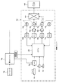
図2は、上記ENGレンズ10におけるズーム制御に関連する制御系の構成を示した図である。同図に示すように駆動ユニット14にはCPU50は内蔵されており、そのCPU50には、上記ズームシーソーレバー28の操作状態(変位量)に応じた電圧の制御信号がA/D変換器52を介してCPU50に与えられる。また、上記サーボON/OFFスイッチ30やクラッチ自動切替機能ON/OFFスイッチ32のオン/オフ状態を示す信号が与えられる。
FIG. 2 is a diagram showing a configuration of a control system related to zoom control in the
ズームシーソーレバー28から出力される制御信号の値は、ズームモータ58の回転速度、即ち、ズームモータ58と連動するズームリング18の回転速度又はズームレンズの移動速度(以下、ズームの速度という)の目標値を示しており、ズームシーソーレバー28が無操作のときの基準位置において0(V)となり、ズームシーソーレバー28が操作されると、その操作方向(ワイド側又はテレ側)と操作の大きさに応じて正負に大きさが変化するようになっている。尚、ズームシーソーレバー28の操作方向及び操作の大きさをズームシーソーレバー28の変位量という。また、CPU50では、その制御信号の値が0の場合に、ズームシーソーレバー28からの制御信号がないものと判断され、その場合にズームシーソーレバー28の操作が行われていないものと判断される。但し、ズームシーソーレバー28が無操作のときの基準位置において制御信号の値が0以外の値であってもよく、その場合、CPU50では、その値の制御信号が与えられている場合にズームシーソーレバー28の操作が行われていないものと判断する。
The value of the control signal output from the
CPU50は、サーボON/OFFスイッチ30がオンされている場合にはズームシーソーレバー28から与えられた制御信号の値、又は、それに応じた値の駆動信号をD/A変換器54を介してアンプ56に出力する。アンプ56からズームモータ58には、与えられた駆動信号の値に応じた電圧が印加され、ズームモータ58がその駆動信号の値に応じた方向及び速度で回転する。即ち、ズームシーソーレバー28の変位量に応じた速度(方向及び速さ(以下同じ))でズームモータ58が回転する。
When the servo ON /
ズームモータ58はクラッチ機構(以下、クラッチという)60を介して上記レンズ鏡胴12のズームリング18に連結されており、サーボON/OFFスイッチ30がオンで、少なくともズームシーソーレバー28が操作されているとき(制御信号が0以外のとき)には、後述のようにクラッチ60がオン(連結)されているため、ズームモータ58の動力がクラッチ60を介してズームリング18に伝達される。これによって、ズームリング18もサーボモータ58と同様にズームシーソーレバー28の変位量に応じた速度で回転し、更に、ズームリング18と連動するズームレンズがズームシーソーレバー28の変位量に応じた速度で移動する。このようにしてズームシーソーレバー28の操作に従ったズームの速度制御が行われる。
The
尚、ズームモータ58にはポテンショメータ62が連結されており、そのポテンショメータ62からはズームモータ58の回転位置、即ち、ズームモータ58と連動するズームリング18の回転位置又はズームレンズの位置(以下、ズームの位置という)に対応した電圧が出力される。その電圧値は現在のズームの位置を示す現在値としてA/D変換器64を介してCPU50に与えられている。
A
上記クラッチ60はクラッチモータ70によってオン(連結)とオフ(切断)が切り替えられるようになっており、CPU50から出力される駆動信号がD/A変換器66を介してアンプ68に与えられ、その駆動信号に従ってアンプ68からクラッチモータ70に印加される電圧によってクラッチモータ70が駆動されるようになっている。CPU50は、クラッチモータ70に連結されたポテンショメータ72の出力電圧をA/D変換器74を介して取得することによってクラッチモータ70の回転位置を検出しながらクラッチモータ70を制御し、クラッチ60のオン/オフを制御する。尚、クラッチ60のオン/オフ制御については後述する。また、クラッチ60の機構はどのような機構であってもよく、モータ以外によってクラッチのオン/オフが切り替えられる場合であってもよい。
The clutch 60 is turned on (connected) and turned off (disconnected) by a
また、同図には、コントローラ76によってリモート操作される雲台システム78の雲台に図示しないテレビカメラを搭載し、そのテレビカメラにおいて上記ENGレンズ10を使用した場合に、コントローラ76を雲台システム78を介してENGレンズ10の駆動ユニット14に接続した場合の構成が示されている。ここで、コントローラ76でのズームの操作が、例えばズームの目標位置を指定するもので、コントローラ76から雲台システム78にはその操作に応じた目標位置を示す値(目標値)の制御信号(位置制御信号)が出力されるものとする。一方、雲台システム78では、駆動ユニット14のポテンショメータ62からズームの現在位置を示す電圧値が取得され、その現在位置を示す電圧値(現在値)とコントローラ76から与えられた目標値との差の値(又は、差に比例した値)の電圧信号が、ズームの目標速度を示す制御信号として駆動ユニット14に出力されるものとする。
Further, in the figure, when a TV camera (not shown) is mounted on a pan head of a
このようなシステムが構成された場合に、サーボON/OFFスイッチ30がオンされているときには、駆動ユニット14のCPU50は、雲台システム78から外部入力された制御信号の値をA/D変換器52を介して取得する。そして、ズームシーソーレバー28が操作された場合と同様にその制御信号に従ってズームの速度制御を行う。これによって、コントローラ76によって指定された目標位置とズームの現在位置とが一致するようにズームモータ58が駆動され、駆動ユニット14、コントローラ76、及び、雲台システム78を含めたレンズ制御システム全体としてズームの位置制御が行われるようになっている。尚、コントローラ76から出力された目標位置を示す制御信号をそのまま駆動ユニット14のCPU50に与えて、CPU50で位置制御を行うようにしてもよい。
When such a system is configured, when the servo ON /
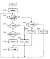
次に、図3のフローチャートを用いてクラッチ60のオン/オフ制御について説明する。CPU50は電源が投入されると、所要の初期設定を行った後(ステップS10)、まず、クラッチ自動切替機能ON/OFFスイッチ32がオンか否かを判定する。即ち、クラッチ自動切替機能が有効か否かを判定する(ステップS12)。もし、YESと判定した場合には、続いて、サーボON/OFFスイッチ30がオンされているか否かを判定する。即ち、サーボが有効か否かを判定する(ステップS14)。ここで、NOと判定した場合には、クラッチモータ70を制御してクラッチ60をオフにし(ステップS20)、手動によるズームリング18の回動操作を可能にする。そして、ステップS12に戻る。
Next, the on / off control of the clutch 60 will be described using the flowchart of FIG. When the power is turned on, the
上記ステップS14においてYES、即ち、サーボが有効と判定した場合には、ズームシーソーレバー28からの制御信号、又は、上記雲台システム78のように駆動ユニット14に接続された機器からの制御信号があるか否かを判定する(ステップS16)。NOと判定した場合、即ち、電動の操作が行われていないと判定した場合にはクラッチ60をオフにし(ステップS20)、手動によるズームリング18の操作を可能にする。そして、ステップS12に戻る。
If YES in step S14, that is, if it is determined that the servo is valid, a control signal from the
上記ステップS16においてYES、即ち、電動の操作が行われていると判定した場合にはクラッチ60をオンにし(ステップS18)、レンズ制御での一処理として上述のようにズームシーソーレバー28等から与えられた制御信号に基づくズームの制御を実行する(ステップS22)。そして、ステップS12に戻る。
If YES in step S16, that is, if it is determined that an electric operation is being performed, the clutch 60 is turned on (step S18), and is given from the
ステップS12〜S22の処理によれば、サーボが有効でクラッチ自動切替機能が有効な場合には、電動の操作が行われているときにクラッチ60が自動でオンとなり、その操作に従って電動でズームリング18が回動操作され、逆に電動の操作が行われていないときにクラッチ60が自動でオフとなり、手動でズームリング18を回動操作できる状態となる。
According to the processing of steps S12 to S22, when the servo is valid and the automatic clutch switching function is valid, the clutch 60 is automatically turned on when the electric operation is performed, and the zoom ring is electrically operated according to the operation. When the
ステップS12においてNO、即ち、クラッチ自動切替機能が無効と判定した場合、CPU50は、クラッチ自動切替の処理を行わずサーボON/OFFスイッチ30のオン/オフのみによってクラッチ60のオン/オフを制御する。即ち、サーボON/OFFスイッチ30がオンされているか否かによってサーボが有効か否かを判定し(ステップS24)、YESと判定した場合には、クラッチ60をオンにする(ステップS26)。そして、ズームシーソーレバー28等から与えられた制御信号に基づくズームの制御を実行し(ステップS22)。ステップS12に戻る。一方、NOと判定した場合にはクラッチ60をオフにし(ステップS28)、手動によるズームリング18の回動操作を可能にし、上記ステップS12に戻る。
If NO in step S12, that is, if it is determined that the clutch automatic switching function is disabled, the
このようにクラッチ自動切替機能を無効にすることは図1で示したような雲台システム78のコントローラ76でズームの位置制御を行う場合に特に有効である。位置制御の場合、コントローラ76での操作を停止している場合であっても例えばポテンショメータ62の出力電圧がノイズ等によって変動すると目標値と現在値とが不一致になったと判断され、それらを一致させるために雲台システム78からCPU50に0(V)以外の制御信号が与えられることになる。そのため、クラッチ自動切替機能が有効になっているとクラッチ60が断続的にオン/オフを繰り返すためクラッチの動作が不安定となり、無駄な電力やクラッチ60の磨耗が増大する。そこで、このような場合にクラッチ自動切替機能を無効にしておくことで、常にクラッチ60をオンにしておくことができ(但し、サーボが有効な場合)、位置制御を行う場合であっても上述のような不具合を未然に防止することができる。
Disabling the clutch automatic switching function in this way is particularly effective when the zoom position control is performed by the
尚、上記実施の形態では、クラッチ自動切替機能のオン/オフをクラッチ自動切替機能ON/OFFスイッチ32によって手動で設定するようにしたが、これに限らず、電動の操作が目標位置を指定する位置制御の操作か、目標速度を指定する速度制御の操作かによってクラッチ自動切替機能のオン/オフを切り替えるようにしてもよい。例えば、図1の雲台システム78は位置制御を行うため、同図の破線で示すように制御方式を示す信号(制御方式判別信号)として位置制御であることを示す信号を駆動ユニット14のCPU50に与えるようにしてもよい。この制御方式判別信号によって位置制御であることが示された場合、CPU50はクラッチ自動切替機能を自動でオフにする。もし、雲台システム78が速度制御を行う場合に、制御方式判別信号によって速度制御であることが示された場合にはクラッチ自動切替機能を自動でオンにする。
In the above embodiment, the on / off of the automatic clutch switching function is manually set by the automatic clutch switching function ON /
また、上記実施の形態では、ENGレンズを用いたシステムにおいて本発明を適用した場合について説明したが、本発明は、上記実施の形態のようにモータとズームレンズのような可動のレンズ群との間がクラッチで連結され、上述のようなクラッチ自動切替機能を備えたレンズ制御システムにおいて適用できる。 In the above embodiment, the case where the present invention is applied to a system using an ENG lens has been described. However, the present invention includes a motor and a movable lens group such as a zoom lens as in the above embodiment. The present invention can be applied to a lens control system in which the two are connected by a clutch and have the clutch automatic switching function as described above.
10…レンズ装置(ENGレンズ)、12…レンズ鏡胴、14…駆動ユニット、16…フォーカスリング、18…ズームリング、20…アイリスリング、24…ケース、28…ズームシーソーレバー、30…サーボON/OFFスイッチ、32…クラッチ自動切替機能ON/OFFスイッチ、50…CPU、58…ズームモータ、60…クラッチ、62、72…ポテンショメータ、70…クラッチモータ、76…コントローラ、78…雲台システム
DESCRIPTION OF
Claims (3)
前記クラッチ自動切替手段による前記クラッチ機構のオン/オフの切替えを有効又は無効に切り替える切替手段を備えたことを特徴とするレンズ制御システム。 A clutch mechanism that connects or disconnects the movable lens group of the photographic lens and the motor, an electric operation means for electrically operating the lens group, and the motor is driven in accordance with an electric operation by the electric operation means. Motor control means, manual operation means for driving the lens group by manual force by manual operation, and when the electric operation is performed by the electric operation means, the clutch mechanism is turned on to turn the lens group and the motor In a lens control system comprising: a clutch automatic switching means for turning off the clutch mechanism and disconnecting between the lens group and the motor when the electric operation by the electric operation means stops.
A lens control system comprising switching means for switching on / off switching of the clutch mechanism by the automatic clutch switching means between valid and invalid.
Priority Applications (1)
| Application Number | Priority Date | Filing Date | Title |
|---|---|---|---|
| JP2004107177A JP2005292445A (en) | 2004-03-31 | 2004-03-31 | Lens control system |
Applications Claiming Priority (1)
| Application Number | Priority Date | Filing Date | Title |
|---|---|---|---|
| JP2004107177A JP2005292445A (en) | 2004-03-31 | 2004-03-31 | Lens control system |
Publications (1)
| Publication Number | Publication Date |
|---|---|
| JP2005292445A true JP2005292445A (en) | 2005-10-20 |
Family
ID=35325435
Family Applications (1)
| Application Number | Title | Priority Date | Filing Date |
|---|---|---|---|
| JP2004107177A Pending JP2005292445A (en) | 2004-03-31 | 2004-03-31 | Lens control system |
Country Status (1)
| Country | Link |
|---|---|
| JP (1) | JP2005292445A (en) |
-
2004
- 2004-03-31 JP JP2004107177A patent/JP2005292445A/en active Pending
Similar Documents
| Publication | Publication Date | Title |
|---|---|---|
| JP2008032992A (en) | DRIVE DEVICE, LIMITATION DEVICE, AND CONTROL METHOD THEREOF | |
| JPH1090585A (en) | Lens controller | |
| JP2001051183A (en) | Lens device | |
| JP5690248B2 (en) | Lens drive device | |
| JP2005292445A (en) | Lens control system | |
| JP3760458B2 (en) | Lens control device for TV camera | |
| JP5690247B2 (en) | Lens drive device | |
| JP4566298B2 (en) | Optical device | |
| JP4366572B2 (en) | Lens control system | |
| JP2583874B2 (en) | Autofocus device and driving method of zoom lens group | |
| JP4855702B2 (en) | Auto focus system | |
| JP4407983B2 (en) | Optical device | |
| US6385399B1 (en) | Optical apparatus and shooting system including zoom function having electrical operation mode and other mode | |
| JP2004102000A (en) | Lens controller | |
| JP2007212957A (en) | Lens controller | |
| JP3918124B2 (en) | TV camera lens control device | |
| JP2001042191A5 (en) | Optical device | |
| JP3807543B2 (en) | Lens control device | |
| JP2000221383A (en) | Lens driving device | |
| JP2001051180A (en) | Lens device | |
| JP2005070635A (en) | Lens information display device | |
| JP2005156738A (en) | Auto focus system | |
| JP3774860B2 (en) | Lens control system | |
| JP2006139115A (en) | Autofocus system | |
| JP2004294657A (en) | Lens device |