JP2004102000A - Lens controller - Google Patents
Lens controller Download PDFInfo
- Publication number
- JP2004102000A JP2004102000A JP2002265185A JP2002265185A JP2004102000A JP 2004102000 A JP2004102000 A JP 2004102000A JP 2002265185 A JP2002265185 A JP 2002265185A JP 2002265185 A JP2002265185 A JP 2002265185A JP 2004102000 A JP2004102000 A JP 2004102000A
- Authority
- JP
- Japan
- Prior art keywords
- zoom
- limit position
- limit
- control
- lens
- Prior art date
- Legal status (The legal status is an assumption and is not a legal conclusion. Google has not performed a legal analysis and makes no representation as to the accuracy of the status listed.)
- Pending
Links
Images


Abstract
Description
【0001】
【発明の属する技術分野】
本発明はレンズ制御装置に係り、特に撮影レンズのズームの駆動範囲を所望の範囲に制限するズームリミット機能を備えたレンズ制御装置に関する。
【0002】
【従来の技術】
従来、テレビカメラ用の撮影レンズ(ENGレンズ、EFPレンズ等のレンズ装置)において、メカ端で規制されるズームの全可動範囲に対してワイド側及びテレ側の所望の位置にリミット位置を設定し、そのリミット位置の範囲内にズームの駆動範囲を制限するズームリミット機能が知られている。
【0003】
また、テレビカメラ用の撮影レンズのズーム制御において、複数の制御方式(操作方式)を選択的に使用可能にしたものが知られている。例えば、取材等に使用されるENGレンズの場合、レンズ鏡胴側部にモータ等を内蔵した駆動ユニットが装着されており、この駆動ユニットに設けられているズームシーソスイッチを操作するとモータの駆動力によりレンズ鏡胴のズームリングが回動してズーム(変倍レンズ)が駆動されるようになっている(サーボ駆動方式)。一方、駆動ユニットのモータとズームリングとの間に配置されるクラッチを所定のレバーで切り離し、ズームリングを直接手動で回動操作すると、その手動力によりズームを駆動することもできるようになっている(マニュアル駆動方式)。尚、一般にクラッチが接続されてサーボ駆動可能な状態でもマニュアル駆動は可能であり、また、クラッチの切替操作なく、サーボ駆動とマニュアル駆動の切替えをクラッチレスにより行うものも知られている。
【0004】
また、主にスタジオで使用される箱型のEFPレンズの場合、一般に、ズームデマンドと呼ばれるコントローラが接続され、そのズームデマンドからのコントロール信号によってズームがサーボ駆動されるようになっている。一方、ズームデマンドと共に、従来から知られている一軸二操作棒の押し引き操作によりズームをマニュアル駆動できるようにしたものも知られており、サーボ駆動方式とマニュアル駆動方式の切替えを上述と同様にクラッチの切替えで行うもの、又は、クラッチレスで行うもの等が提案されている。また、一軸二操作棒の押し引き操作を電気信号により検出し、ズームデマンドと共に一軸二操作棒の押し引き操作によりズームをサーボ駆動するものも提案されている。
【0005】
ところで、上述のように2通り又はそれ以上(本実施の形態の説明では2通りとする)の制御方式によりズーム制御を可能にした場合、各制御方式でズームの駆動範囲が相違する場合がある。尚、ズームを駆動する駆動機構(動力源と動力伝達機構)が異なる場合に限らず、駆動機構が同じであってもズームの動作速度や位置を指示する指示手段(又は操作手段)が異なれば制御方式が異なるものとする。
【0006】
例えば、上述のENGレンズ等において、サーボ駆動によるズームの駆動範囲を所望のリミット位置(ワイド側とテレ側それぞれのリミット位置)の範囲内に制限するズームリミット機能を搭載したものが提案されている。一方、マニュアル駆動の場合には、そのズームリミット機能による駆動範囲の制限は作用せず、メカ端で規制される全可動範囲でズームを駆動させることができる。このため、サーボ駆動方式とマニュアル駆動方式とではズームの駆動範囲が相違する。
【0007】
また、複数の制御方式によるズームの駆動範囲を、それぞれ個別のリミット位置により制限できるようにした場合も、各制御方式でズームの駆動範囲が相違する可能性がある。
【0008】
このように各制御方式によるズームの駆動範囲が相違する場合、従来は、ある制御方式により、ズームが他の制御方式におけるリミット位置を超えた位置に設定されると、他の制御方式が有効になった時点でズームリミット機能の制御によりズームがリミット位置に即座に戻されるようになっている。
【0009】
例えば、クラッチレスのズームリミット機能付きENGレンズ(駆動ユニット)においては、原則としてサーボ駆動方式が常時有効となっており、ズームリングを直接手動操作している間だけマニュアル駆動方式によるズームの駆動が有効となる。また、ズームリミット機能もオンであればサーボ駆動方式によるズームの駆動に対して常に有効な状態にある。このような場合に、ズームリングを直接手動操作してマニュアル駆動によりズームをズームリミット機能のリミット位置を超えた位置に移動させることもできるが、ズームリングの手動操作を停止すると(ズームリングの操作力を解除すると)、サーボ駆動方式が有効となりズームリミット機能の制御によりズームがリミット位置に戻されることになる。
【0010】
【特許文献1】
特開平10−39193
【0011】
【発明が解決しようとする課題】
しかしながら、いずれかの制御方式によってズームを駆動した後、他の制御方式に切り替えた際に、ズームの位置が操作者の何らの操作もなく他の制御方式に対して設定されたリミット位置に戻されるのは好ましくない場合がある。特に、上述のようなクラッチレスのリミット機能付きENGレンズの例においては、操作者の意思でズームリングを直接手動操作し、マニュアル駆動方式によりズームを、リミット位置を超えた位置に移動させたにもかかわらず、ズームリングの手動操作を停止すると同時にズームリミット機能によりズームがリミット位置に戻されてしまうため、カメラマンの意思と反した動作となり、また、急激な画角変化が生じてしまうという問題があった。
【0012】
本発明はこのような事情に鑑みてなされたもので、操作者の意思を尊重した操作性の良いズームリミット機能の制御を実現するレンズ制御装置を提供することを目的とする。
【0013】
【課題を解決するための手段】
前記目的を達成するために、請求項1に記載の発明は、撮影レンズのズームを制御する複数の制御手段であって少なくとも第1の制御手段及び第2の制御手段を備え、前記第1の制御手段におけるズームの駆動範囲内にワイド側又はテレ側に関する所望のリミット位置を設定するリミット位置設定手段と、ズームが前記リミット位置をワイド側又はテレ側に超えないように前記第1の制御手段におけるズームの駆動範囲を制限するズーム駆動範囲制限手段と、を備えたレンズ装置において、前記ズーム駆動範囲制限手段は、前記第2の制御手段により駆動されたズームの位置が前記リミット位置設定手段によって設定されたリミット位置を超えた場合には、前記第1の制御手段が有効になっているとき、又は、前記第1の制御手段が無効から有効に切り替えられたときであっても、ズームが前記リミット位置を超えないように前記第1の制御手段によるズームの駆動範囲を制限する制御を実行しないことを特徴としている。
【0014】
また、請求項2に記載の発明は、請求項1に記載の発明において、前記ズーム駆動範囲制限手段は、前記第2の制御手段により駆動されたズームの位置が前記リミット位置設定手段によって設定されたリミット位置を超えた場合には、該ズームの位置を実リミット位置として設定し、ズームが前記実リミット位置を超えないように前記第1の制御手段によるズームの駆動範囲を制限すると共に、ズームが前記リミット位置設定手段によって設定されたリミット位置に一致するまで前記第1の制御手段により駆動されたズームの位置を前記実リミット位置として更新することを特徴としている。
【0015】
また、請求項3に記載の発明は、請求項1又は請求項2に記載の発明に於いて、前記第1の制御手段は、ズームをモータにより駆動し、前記第2の制御手段は、ズームを手動力により駆動することを特徴としている。
【0016】
本発明によれば、第2の制御手段により駆動されたズームの位置が第1の制御手段におけるズームリミット機能(リミット位置設定手段及びズーム駆動範囲制限手段)のリミット位置を超えた場合に、第1の制御手段が有効に切り替えられたとき等であっても、ズームリミット機能の制御によりズームをリミット位置に移動させないようにしたため、ズームの動作がカメラマンの意思と反した動作となり、また、急激な画角変化が生じてしまうという不具合が防止される。また、請求項2の発明のように第2の制御手段によりズームが第1の制御手段におけるリミット位置を超えた場合にそのリミット位置に一致するまで第1の制御手段によるズームの駆動がリミット位置の内側への方向のみに制限されるようになるため、第1の制御手段における本来のリミット位置に対応したズームの駆動範囲にズームを戻す作用が完全に無効になることはない。これによって、操作者の意思を尊重した操作性の良いズームリミット機能の制御が実現される。
【0017】
【発明の実施の形態】
以下添付図面に従って本発明に係るレンズ制御装置の好ましい実施の形態について詳説する。
【0018】
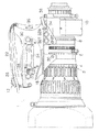
図1は、本発明が適用されるENGレンズ及び駆動ユニットの外観を示した平面図である。同図に示すENGレンズ1は、ENGカメラ等の放送用テレビカメラに用いられるインナーフォーカス式ズームレンズであり、レンズ鏡胴2には、フォーカスリング4、ズームリング6及びアイリスリング8が設けられ、レンズ鏡胴2の後端部にはエクステンダ(装置)10が設けられている。また、レンズ鏡胴2の側部には前記フォーカスリング4、ズームリング6及びアイリスリング8をモータ駆動(サーボ駆動)するための駆動ユニット12が設けられている。
【0019】
レンズ鏡胴2の内部構成については図示されていないが、周知の如く、鏡胴内には、前方から順に、固定フォーカスレンズ、移動フォーカスレンズ、変倍レンズ、アイリス、及びリレーレンズ等が設けられ、その後方に、エクステンダ10が配置される。そして、フォーカスリング4を回動することにより移動フォーカスレンズが光軸に沿って前後移動してフォーカス調整が行われ、ズームリング6を回動することにより、変倍レンズが光軸に沿って前後移動してズーム調整が行われる。また、アイリスリング8を回動することによりアイリスの絞り径が調整されるようになっている。尚、エクステンダ10は所定のレバーによって倍率が切り替えられるようになっている。
【0020】
駆動ユニット12はケース18を有し、このケース18はビス20、20によりレンズ鏡胴2の側部に取り付けられる。ケース18内には、図示せぬフォーカス駆動用モータが配置され、このフォーカス駆動用モータは、図示せぬギヤ伝達機構を介して前記フォーカスリング4と噛み合い、フォーカスリング4を回転駆動する。尚、駆動ユニット12にフォーカス駆動用モータが搭載されていないものもあり、本実施の形態では、フォーカス駆動用モータが搭載されていなくてもよい。また、ケース18内には、ズーム駆動用モータが配置され、このズーム駆動用モータは、図示せぬギヤ伝達機構を介して前記ズームリング6と噛み合い、ズームリング6を回転駆動する。同様に、ケース18内には、図示せぬアイリス駆動用モータが配置され、このアイリス駆動用モータは、図示せぬギヤ伝達機構を介して前記アイリスリング8と噛み合い、アイリスリング8を回転駆動する。
【0021】
ケース18の側面にはグリップバンド22が設けられており、カメラマンはこのグリップバンド22の中に右手(親指以外の4本の指)を挿入することにより、レンズ鏡胴2を保持することができ、また、ケース18の各所に配置されたスイッチ等の各種操作部材を各指により操作することができるようになっている。
【0022】
操作部材として例えば、ケース18の上面にはズームシーソスイッチ24、アイリスのオート/マニュアルモード切替スイッチ26、アイリスモーメンタリースイッチ28、リターンスイッチ30等が設けられている。また、ケース18の上面の取付用ビス20、20の近くには、ワイド側リミット位置設定スイッチ32W、テレ側リミット位置設定スイッチ32T、ズームリミットオン・オフスイッチ34が設けられている。また、ケース18の後面にはVTRスイッチ36、ズーム最大スピード調節ツマミ38が設けられている。
【0023】
これらの操作部材のうちズーム制御に関する操作部材の作用について説明すると、ズームシーソスイッチ24は、中立位置を基準に揺動自在に設置されており、ズームシーソスイッチ24をワイド(W)側又はテレ(T)側に押し込み操作すると、その押し込み方向に対応した方向に、且つ、その押し込み量に対応した回転速度でズーム駆動用モータが回動する。そして、ズーム駆動用モータが回動することによりギヤ伝達機構を介して前記ズームリング6がワイド側又はテレ側にズーム駆動用モータの回転速度に対応した速度で回動する。これにより、ズーム(変倍レンズ)がズームシーソスイッチ24の押し込み方向に対応した方向に、且つ、ズームシーソスイッチ24の押し込み量に対応した動作速度(ズームスピード)で駆動される。尚、このズームの駆動はサーボ機構によるものでズームシーソスイッチ24を用いたズームの制御方式をサーボ駆動方式という。
【0024】
また、ズーム最大スピード調節ツマミ38を回動操作して設定位置を変更することにより、ズームシーソスイッチ24を最も深く押し込み操作した場合のズームスピード(ズーム最大スピード)を適宜変更することができるようになっている。
【0025】
また、ワイド側リミット位置設定スイッチ32W、テレ側リミット位置設定スイッチ32T、及び、ズームリミットオン・オフスイッチ34は、サーボ駆動方式におけるズームの駆動範囲を所定のワイド側リミット位置とテレ側リミット位置の間の範囲に制限するズームリミット機能に関連する操作部材である。例えば、ズームシーソスイッチ24を操作し、ワイド側にそれ以上ズームが移動しないようにする位置にズーム(変倍レンズ)を設定し、ワイド側リミット位置設定スイッチ32Wを押すと、そのときのズームの位置がワイド側リミット位置としてメモリに記憶される。同様に、テレ側にそれ以上ズームが移動しないようにする位置にズームを設定し、テレ側リミット位置設定スイッチ32Tを押すと、そのときのズームの位置がテレ側リミット位置としてメモリに記憶される。また、ズームリミットオン・オフスイッチ34を押すごとに、ズームリミット機能がオン(有効)からオフ(無効)、又は、オフからオンに切り替わる。ズームリミット機能がオンの状態のときに、ズームシーソスイッチ24を操作してサーボ駆動によりズームを駆動すると、ズームの駆動範囲は、メモリに記憶されたワイド側リミット位置よりもテレ側で、且つ、メモリに記憶されたテレ側リミット位置よりもワイド側の範囲に制限されるようになっている。即ち、ズームがワイド側リミット位置、又は、テレ側リミット位置を超えるようなズームシーソスイッチ24の操作を行った場合に、ズームがそれらのリミット位置で停止する。
【0026】
尚、ズームリミット機能がオフの場合には、ズームシーソスイッチ24の操作によりズームをメカ端で規制される全可動範囲でサーボ駆動することができる。また、ワイド側リミット位置とテレ側リミット位置のいずれか一方のみを有効にできるようにしてもよい。
【0027】
ところで、上記駆動ユニット12は、原則としてサーボ駆動方式が常時有効であり、また、ズームリミット機能もオンであればサーボ駆動方式によるズームの駆動に対して常に有効な状態にある。一方、ズームリング6を直接手動操作することによってもズームを駆動することができるようになっており、サーボ駆動方式と、ズームリング6を直接手動操作してズームを駆動するマニュアル駆動方式との切替えをクラッチレスで行えるようなっている。即ち、サーボ駆動方式とマニュアル駆動方式との特別な切替操作は不要である。マニュアル駆動方式においては、ズームをメカ端で規制される全可動範囲で駆動することができ、ズームリミット機能のリミット位置を超えた位置に移動させることもできるが、更に、本実施の形態の駆動ユニット12では、マニュアル駆動方式によりズームをリミット位置を超えた位置に移動させてズームリングの手動操作を停止(ズームリングの操作力を解除)しても、ズームがその位置に停止した状態に維持されるようになっている。即ち、ズームリングの手動操作を停止すると、サーボ駆動方式が有効となり、ズームリミット機能もオンであれば有効となるが、ズームリミット機能の制御によりズームがリミット位置に戻されるということはない。
【0028】
もし、上述のようにズームリミット機能をオンにした状態でマニュアル駆動方式によりズームをワイド側リミット位置(又はテレ側リミット位置)を超えた位置に設定したとする。そして、ズームシーソスイッチ24を操作し、ワイド側リミット位置(又はテレ側リミット位置)よりも更にワイド側(又はテレ側)にズームを移動させようとした場合には、ズームは駆動されない。一方、ズームシーソスイッチ24を操作し、ワイド側リミット位置(又はテレ側リミット位置)に近づく方向にズームを移動させようとした場合には、その操作に従ってズームが駆動される。尚、ズームがワイド側リミット位置(又はテレ側リミット位置)に達するまでは、ワイド側リミット位置(又はテレ側リミット位置)よりも更にワイド側(又はテレ側)にズームを駆動することはできない。ズームがワイド側リミット位置(又はテレ側リミット位置)に達すると、通常のズームリミット機能の制御により、ズームの駆動範囲がワイド側リミット位置とテレ側リミット位置の範囲に制限されるようになっている。
【0029】
図2は、上記ENGレンズ1及び駆動ユニット12におけるズーム制御に関する構成を示したブロック図である。同図に示すように駆動ユニット12には、CPU50が内蔵されており、上記操作部材として示したズームシーソスイッチ24の操作量(押し込み方向及び押し込み量)はポテンショメータ52によって検出され、その検出信号がズームシーソスイッチ24からのズームの制御信号としてCPU50に与えられるようになっている。また、ワイド側リミット位置設定スイッチ32W、テレ側リミット位置設定スイッチ32T、ズームリミットオン・オフスイッチ34のオン/オフ状態を示す信号等もCPU50に与えられるようになっている。CPU50の処理についての詳細は後述するが、例えば、CPU50は、ズームシーソスイッチ24からの制御信号に対応する値の制御信号を、ズーム駆動用モータ58の回転速度(方向及び大きさ)の指示値を示す制御信号としてD/A変換器54に出力する。尚、CPU50から出力される制御信号の値が0のときは停止を意味する。D/A変換器54に出力された制御信号は、その値に対応した電圧信号に変換されてアンプ56に入力する。一方、アンプ56には、ズーム駆動用モータ58の実際の回転速度に対応した電圧値の検出信号が回転速度検出センサ60からフィードバックされており、アンプ56は、CPU50からの制御信号の電圧と回転速度検出センサ60からの検出信号の電圧との差分を所定のゲインで増幅して、その電圧をズーム駆動用モータ58に印加する。これにより、ズーム駆動用モータ58がCPU50から出力された制御信号の値に対応する回転速度で回動する。ズーム駆動用モータ58が回転すると、ズームリング6が図示しないギア伝達機構により回動されて変倍レンズ62が移動する。これによってズームがズームシーソスイッチ24の押し込み方向及び押し込み量に応じた方向及び速度で駆動される。尚、ズームリング6を直接手動で回動操作してズームを駆動することも可能である。
【0030】
また、ズーム(変倍レンズ62)の位置が位置検出センサ64によって検出され、その検出信号がA/D変換器66を介してCPU50に与えられるようになっている。CPU50は、ズームリミット機能がオンの場合には、ズームの位置がメモリ68に記憶されているリミット位置(ワイド側リミット位置又はテレ側リミット位置)を超えないようにD/A変換器54に出力する制御信号の値をズームシーソスイッチ24からの制御信号に対応して決められる値に対して補正した値とする。
【0031】
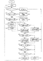
次に、CPU50の処理について説明する。図3はCPU50の処理内容及び処理手順を示したフローチャートである。尚、操作者がズームリング6を直接回動操作した場合には、CPU50が以下の処理を実行している間にCPU50の処理とは無関係にズームが駆動されている。CPU50は、まず、所要の初期設定を行うと(ステップS10)、次に、ズームリミット機能がオンか否かを判定する(ステップS12)。即ち、ズームリミットオン・オフスイッチ34がオンされたか否かを検出し、オンされた場合に、それまでズームリミット機能がオフであった場合にはオン(YES)と判定し、それまでズームリミット機能がオンであった場合にはオフ(NO)と判定する。これによって、NO(ズームリミット機能がオフ)と判定した場合には、CPU50は、ズームシーソスイッチ24から制御信号を読み込み(ステップS14)、その制御信号に基づいて、D/A変換器54に制御信号を出力する(ステップS16)。そして、ステップS12に戻る。これにより、ズームシーソスイッチ24の操作に基づいてズームがサーボ駆動されると共に、メカ端で規制される全可動範囲でズームが駆動可能となる。
【0032】
一方、ステップS12においてYES(ズームリミット機能がオン)と判定した場合には、次にワイド側リミット位置設定スイッチ32Wがオンされたか否かを判定する(ステップS18)。YESと判定した場合には、現在のズームの位置を位置検出センサ64から取得し、その位置をワイド側リミット位置W_MEMOとしてメモリ68に記憶させる(ステップS20)。そして、ステップS22に移行する。一方、ステップS18においてNOと判定した場合には、ステップS20の処理を行わずにステップS22に移行する。
【0033】
ここで、図4(A)に示すようにズームの全駆動範囲(ワイド側メカ端とテレ側メカ端との間)に対して、ズームが図中LWの位置に設定されていたとする。このとき、ステップS18でYES(ワイド側リミット位置設定スイッチ32Wがオン)と判定した場合、そのLWの位置がワイド側リミット位置W_MEMOとして記憶される。
【0034】
ステップS22に移行するとCPU50は、テレ側リミット位置設定スイッチ32Tがオンされたか否かを判定する(ステップS22)。YESと判定した場合には、現在のズームの位置を位置検出センサ64から取得し、その位置をテレ側リミット位置T_MEMOとしてメモリ68に記憶させる(ステップS24)。そして、ステップS26に移行する。一方、ステップS22においてNOと判定した場合には、ステップS24の処理を行わずにステップS26に移行する。図4(A)において、ズームが図中LTの位置に設定されている場合に、ステップS22でYESと判定したときには、そのLTの位置がテレ側リミット位置T_MEMOとして記憶される。
【0035】
ステップS26に移行するとCPU50は、ズームシーソスイッチ24から制御信号を読み込む(ステップS26)。次いで、現在のズームの位置(現在位置Z_POSI)を位置検出センサ64から読み込む(ステップS28)。
【0036】
続いてCPU50は、ズームの現在位置Z_POSIがワイド側リミット位置を超えているか否かを判定する(ステップS30)。NOと判定した場合には、ワイド側リミット位置LIMIT_WをステップS20でメモリ68に記憶したワイド側リミット位置W_MEMOに設定する(LIMIT_W=W_MEMO)(ステップS32)。尚、ワイド側リミット位置LIMIT_Wを以下、実ワイド側リミット位置LIMIT_Wという。
【0037】
例えば、ステップS28で検出したズームの現在位置Z_POSIが図4(A)におけるP1又はP3の位置であった場合には、ステップS30においてNOと判定され、実ワイド側リミット位置LIMIT_Wは、図4(B)に示すようにメモリ68に記憶したワイド側リミット位置W_MEMO、即ち、LWの位置となる。
【0038】
一方、ステップS30でYESと判定した場合には、実ワイド側リミット位置LIMIT_Wを、ステップS28において読み込んだ現在位置Z_POSIに設定する(LIMIT_W=Z_POSI)(ステップS34)。
【0039】
例えば、ステップS28で検出したズームの現在位置Z_POSIが図4(A)におけるP2の位置であった場合には、ステップS30においてYESと判定され、実ワイド側リミット位置LIMIT_Wは、図4(B)に示すようにズームの現在位置Z_POSI、即ち、P2の位置となる。
【0040】
続いてCPU50は、ズームの現在位置Z_POSIがテレ側リミット位置を超えているか否かを判定する(ステップS36)。NOと判定した場合には、テレ側リミット位置LIMIT_TをステップS24でメモリ68に記憶したテレ側リミット位置T_MEMOに設定する(LIMIT_T=T_MEMO)(ステップS38)。尚、テレ側リミット位置LIMIT_Tを以下、実テレ側リミット位置LIMIT_Tという。
【0041】
例えば、ステップS28で検出したズームの現在位置Z_POSIが図4(A)におけるP1又はP2の位置であった場合には、ステップS36においてNOと判定され、実テレ側リミット位置LIMIT_Tは、図4(B)に示すようにメモリ68に記憶したテレ側リミット位置T_MEMO、即ち、LTの位置となる。
【0042】
一方、ステップS36でYESと判定した場合には、実テレ側リミット位置LIMIT_Tを、ステップS28において読み込んだ現在位置Z_POSIに設定する(LIMIT_T=Z_POSI)(ステップS40)。
【0043】
例えば、ステップS28で検出したズームの現在位置Z_POSIが図4(A)におけるP3の位置であった場合には、ステップS36においてYESと判定され、実テレ側リミット位置LIMIT_Tは、図4(B)に示すようにズームの現在位置Z_POSI、即ち、P3の位置となる。
【0044】
次に、CPU50は、ズームが実ワイド側リミット位置LIMIT_Wより外側へ駆動するようなズームシーソスイッチ24の操作が行われたか否かを判定する(ステップS42)。NOと判定した場合には、続いて、ズームが実テレ側リミット位置LIMIT_Tより外側へ駆動するようなズームシーソスイッチ24の操作が行われたか否かを判定する(ステップS44)。更に、NOと判定した場合には、ズームシーソスイッチ24からの制御信号に基づく制御信号をD/A変換器54に出力し、ズームシーソスイッチ24からの制御信号に従ってズームを駆動する(ステップS46)。一方、ステップS42又はステップS44でYESと判定した場合には、0の値の制御信号をD/A変換器54に出力し、ズームを駆動させない(ステップS48)。ステップS46又はステップS48の処理が終了すると、ステップS12の処理に戻る。
【0045】
例えば、図4(A)において、P1の位置にズームが設定されている場合には、ズームシーソスイッチ24をワイド側とテレ側のいずれの方向に操作してもステップS42及びステップS44でNOと判定され、ズームシーソスイッチ24の操作にしたがってズームが駆動される。当然、ズームシーソスイッチ24を操作しなければ、ズームはP1で停止した状態となる。
【0046】
一方、図4(A)において、P2の位置にズームが設定されている場合には、ズームリング6を直接手動操作した場合は別として、ズームシーソスイッチ24を操作しなければ、ステップS42及びステップS44でNOと判定され、且つ、ズームシーソスイッチ24を操作していないためステップS48の処理でズームがP2の位置で停止した状態で維持される。即ち、マニュアル駆動方式によってワイド側リミット位置W_MEMOを超えた位置にズームを設定した場合には、ズームシーソスイッチ24を操作しなければその位置にズームが停止した状態となり、ズームリミット機能の制御によりズームがワイド側リミット位置W_MEMOに戻されることはない。
【0047】
また、P2の位置にズームが設定されている場合に、ズームシーソスイッチ24をテレ側に操作した場合には、ステップS42及びステップS44でNOと判定され、ズームシーソスイッチ24の操作にしたがってズームが駆動される。これに対して、P2の位置にズームが設定されている場合に、ズームシーソスイッチ24をワイド側に操作した場合には、ステップS42でYESと判定され、ズームが停止の状態に維持される。
【0048】
即ち、サーボ駆動方式によるズームの駆動範囲は、実ワイド側リミット位置LIMIT_Wを超えないように制限される。
【0049】
また、以上のステップS12〜ステップS48までルーチンは繰り返し実行されるようになっており、次のルーチンにおいてズームが図4(A)のP2´の位置に移動していたとすると、実ワイド側リミット位置LIMIT_Wは、ステップS30及びステップS34の処理により図4(B)に示すようにそのP2´の位置に変更され、サーボ駆動方式によるズームの駆動範囲の制限も変更される。ズームがメモリ68に記憶されたワイド側リミット位置W_MEMOよりも内側に移動すると、実ワイド側リミット位置LIMIT_Wは、ワイド側リミット位置W_MEMOの値に固定され、ズームの駆動範囲は通常通りワイド側リミット位置W_MEMOを超えない範囲に制限されるようになる。具体的な説明は省略するがズームがテレ側リミット位置T_MEMOを超えた位置に設定されている場合もズームがワイド側リミット位置W_MEMOを超えた位置に設定されている場合と全く同様である。
【0050】
以上の処理により、マニュアル駆動方式によりズームがメモリ68に登録された本来のワイド側リミット位置W_MEMO又はテレ側リミット位置T_MEMOを超えた位置に設定された場合において、リミット位置を超えている現在位置を実ワイド側リミット位置LIMIT_W又は実テレ側リミット位置LIMIT_Tとして設定し、実ワイド側リミット位置LIMIT_W又は実テレ側リミット位置LIMIT_Tを超えないようにズームの駆動範囲が制限されるため、サーボ駆動方式及びズームリミット機能が有効に切り替わったとき(上記実施の形態ではマニュアル駆動方式における操作が停止したとき)でも、ズームはそのとき設定されている位置に停止した状態で維持されるようになる。即ち、ワイド側リミット位置W_MEMO又はテレ側リミット位置T_MEMOに戻されるということはない。
【0051】
また、このような状態でサーボ駆動方式における操作(ズームシーソスイッチ24の操作)を行った場合、ズームがメモリ68に記憶した本来のワイド側リミット位置W_MEMO又はテレ側リミット位置T_MEMOに到達するまでの間は、実ワイド側リミット位置LIMIT_W又は実テレ側リミット位置LIMIT_Tがズームの現在位置に修正されるため、ワイド側リミット位置W_MEMO又はテレ側リミット位置T_MEMOよりも外側へのズームの駆動が制限される。従って、ズームの駆動範囲を本来の駆動範囲(ワイド側リミット位置W_MEMOとテレ側リミット位置T_MEMOとで制限される範囲)に戻す方向への操作のみが許容され、サーボ駆動方式における本来のリミット位置が全く無効になるという不具合もない。
【0052】
以上、上記実施の形態では、マニュアル駆動方式とサーボ駆動方式との切替えをクラッチレスで行う場合、即ち、特別な切替操作なくマニュアル駆動方式とサーボ駆動方式の切替えを行う場合について説明したが、マニュアル駆動方式とサーボ駆動方式を所定の切替操作によって切り替える場合についても上記実施の形態の内容を同様に適用することができる。
【0053】
即ち、マニュアル駆動方式によりズームがメモリ68に登録された本来のワイド側リミット位置W_MEMO又はテレ側リミット位置T_MEMOを超えた位置に設定された場合において、所定の操作によってサーボ駆動方式及びズームリミット機能が有効に切り替わったときでも、ズームをそのとき設定されている位置に停止した状態で維持することができる。また、このような状態でサーボ駆動方式における操作を行った場合、ズームの駆動範囲を本来の駆動範囲(ワイド側リミット位置W_MEMOとテレ側リミット位置T_MEMOとで制限される範囲)に戻す方向への操作のみを許容することもできる。その処理手順を図5のフローチャートに示す。尚、図3のフローチャートに示した処理内容と略同様であるため、図3のフローチャートの各処理に相当する処理には同一ステップ番号を付してその説明を省略し、異なる処理部分についてのみ説明する。図3のフローチャートと比較して図5のフローチャートには、ステップS44においてNOと判定した後の処理にサーボ駆動方式かマニュアル駆動方式を選択するスイッチ(クラッチの切断、接続の切替スイッチ)がいずれを選択しているかを判断する判断処理が含まれている。この判断処理において、マニュアル駆動方式が選択されていると判断した場合には、ズームシーソスイッチ24の操作状態にかかわらず0の値の制御信号をD/A変換器54に出力し(ステップS48)、サーボ駆動ではズームを駆動しないようにしている。一方、サーボ駆動方式が選択されていると判断した場合には、ズームシーソスイッチ24からの制御信号に基づく制御信号をD/A変換器54に出力し、ズームシーソスイッチ24からの制御信号に従ってズームを駆動するようにしている(ステップS46)。
【0054】
また、ステップS12においてNO、即ち、ズームリミット機能がオフとなっている場合において、ズームシーソスイッチ24からの制御信号に基づく制御信号をD/A変換器54に出力する前にステップS50の判定を行うようにしている。これによって、マニュアル駆動方式が選択されている場合にはズームをサーボ駆動しないようにしている。このようなフローチャートの処理手順によってサーボ駆動方式とマニュアル駆動方式の切替操作が必要な場合においても上記説明したようなズーム制御を実現することができる。
【0055】
また、上記実施の形態では、マニュアル駆動方式によって設定されたズームの位置がサーボ駆動方式におけるリミット位置(メモリに記憶された本来のリミット位置)を超えている場合に、サーボ駆動方式及びズームリミット機能が有効になった後の処理において、サーボ駆動方式によるズームの駆動は本来のリミット位置に到達するまではそのリミット位置の内側に向かう方向にだけ許容され、また、サーボ駆動方式(又はマニュアル駆動方式)の操作によってズームが本来の駆動範囲(本来のリミット位置により規制される範囲)内に移動することによって、本来のリミット位置によりズームの駆動範囲が制限される通常のズームリミット機能の制御に移行するようになっていたが、本発明はこれに限らない。例えば、マニュアル駆動方式によって設定されたズームの位置がサーボ駆動方式におけるリミット位置(本来のリミット位置)を超えている場合に、サーボ駆動方式及びズームリミット機能が有効になった後の処理において、サーボ駆動方式における操作があるまではズームをそのリミット位置を超えた位置に停止させておき、ズーム駆動方式における任意の操作があると、ズームを本来のリミット位置に瞬時に移動させるようにしてもよい。
【0056】
また、上記実施の形態ではENGレンズにおいてマニュアル駆動方式とサーボ駆動方式が可能な場合のズームの制御に関して説明したが、本発明は、これに限らない。例えば、ズーム制御に関して複数の制御手段(ズームを駆動する駆動機構又はズームの動作速度や位置を指示する指示手段(又は操作手段)が異なる場合には異なる制御手段とする)を有する場合において、ズームリミット機能等によってズームの駆動範囲が異なる可能性のある制御手段の間でのズームの制御に関して適用できる。例えば、複数のズームコントローラを複数接続することができ、所定の切替操作で、又は、切替操作なく、所望のズームコントローラでズームを制御できるようにした場合であって、コントローラごとにズームリミット機能のリミット位置を設定できる場合や、従来知られているように、EFPレンズにおいてズームコントローラと一軸二操作棒とを切り替えてズームを駆動することができ、ズームコントローラにのみズームリミット機能が有効に作用する場合等がある。
【0057】
【発明の効果】
以上説明したように本発明に係るレンズ制御装置によれば、第2の制御手段により駆動されたズームの位置が第1の制御手段におけるズームリミット機能のリミット位置を超えた場合に、第1の制御手段が有効に切り替えられたとき等であっても、ズームリミット機能の制御によりズームをリミット位置に移動させないようにしたため、ズームの動作がカメラマンの意思と反した動作となり、また、急激な画角変化が生じてしまうという不具合が防止される。また、請求項2の発明のように第2の制御手段によりズームが第1の制御手段におけるリミット位置を超えた場合にそのリミット位置に一致するまで第1の制御手段によるズームの駆動がリミット位置の内側への方向のみに制限されるようになるため、第1の制御手段における本来のリミット位置に対応したズームの駆動範囲にズームを戻す作用が完全に無効になることはない。これによって、操作者の意思を尊重した操作性の良いズームリミット機能の制御が実現される。
【図面の簡単な説明】
【図1】図1は、本発明が適用されるENGレンズ及び駆動ユニットの外観を示した平面図である。
【図2】図2は、上記ENGレンズ1及び駆動ユニット12におけるズーム制御に関する構成を示したブロック図である。
【図3】図3は、駆動ユニットのCPUにおけるズーム制御に関する処理内容及び処理手順を示したフローチャートである。
【図4】図4は、ズームリミット機能の制御の説明に使用した説明図である。
【図5】図5は、他の実施の形態における駆動ユニットのCPUにおけるズーム制御に関する処理内容及び処理手順を示したフローチャートである。
【符号の説明】
1…ENGレンズ、2…レンズ鏡胴、6…ズームリング、12…駆動ユニット、24…ズームシーソスイッチ、32W…ワイド側リミット位置設定スイッチ、32T…テレ側リミット位置設定スイッチ、34…ズームリミットオン・オフスイッチ、50…CPU、52…ポテンショメータ、54…D/A変換器、56…アンプ、58…ズーム駆動用モータ、60…回転速度検出センサ、62…変倍レンズ、64…位置検出センサ、68…メモリ[0001]
TECHNICAL FIELD OF THE INVENTION
The present invention relates to a lens control device, and more particularly, to a lens control device having a zoom limit function of limiting a zoom drive range of a photographing lens to a desired range.
[0002]
[Prior art]
2. Description of the Related Art Conventionally, in a photographing lens for a television camera (lens apparatus such as an ENG lens and an EFP lens), a limit position is set to a desired position on a wide side and a tele side with respect to the entire movable range of zoom regulated by a mechanical end. There is known a zoom limit function for limiting a zoom driving range within the range of the limit position.
[0003]
Further, in zoom control of a photographing lens for a television camera, there is known a zoom lens in which a plurality of control methods (operation methods) can be selectively used. For example, in the case of an ENG lens used for news gathering or the like, a drive unit having a built-in motor or the like is mounted on the lens barrel side, and when a zoom seesaw switch provided in this drive unit is operated, the driving force of the motor is increased. As a result, the zoom ring of the lens barrel is rotated to drive the zoom (magnifying lens) (servo drive system). On the other hand, if the clutch disposed between the motor of the drive unit and the zoom ring is disengaged with a predetermined lever and the zoom ring is directly and manually rotated, the zoom can be driven by the manual force. (Manual drive system). In general, manual driving is possible even in a state in which a clutch is connected and servo driving is possible, and there is also known a method in which switching between servo driving and manual driving is performed without a clutch without clutch switching operation.
[0004]
In the case of a box-shaped EFP lens mainly used in a studio, a controller called a zoom demand is generally connected, and the zoom is servo-driven by a control signal from the zoom demand. On the other hand, it is also known that a zoom can be manually driven by a push / pull operation of a conventionally known one-axis two-operation rod together with a zoom demand, and switching between a servo drive system and a manual drive system is performed in the same manner as described above. A method in which clutch switching is performed, a method in which clutch switching is performed, and the like have been proposed. Further, there has been proposed an apparatus that detects a push / pull operation of a single-axis / two-operation rod by an electric signal, and servo-drives a zoom by a push / pull operation of a single-axis / two-operation rod together with a zoom demand.
[0005]
By the way, when zoom control is enabled by two or more control methods (two in the description of the present embodiment) as described above, the drive range of zoom may be different in each control method. . The present invention is not limited to the case where the driving mechanism for driving the zoom (the power source and the power transmission mechanism) is different. Even if the driving mechanism is the same, if the instructing means (or the operating means) for instructing the operating speed and position of the zoom is different. The control method is different.
[0006]
For example, among the above-described ENG lenses and the like, those equipped with a zoom limit function that limits the drive range of zoom by servo drive to within a desired limit position (limit positions on the wide side and the tele side) are proposed. . On the other hand, in the case of manual driving, the driving range is not limited by the zoom limit function, and the zoom can be driven in the entire movable range regulated by the mechanical end. Therefore, the zoom drive range is different between the servo drive method and the manual drive method.
[0007]
In addition, even when the zoom driving ranges by a plurality of control methods can be limited by individual limit positions, the zoom driving ranges may be different in each control method.
[0008]
As described above, in the case where the zoom driving range is different depending on each control method, conventionally, when the zoom is set to a position beyond the limit position in the other control method, the other control method is effectively performed. At this point, the zoom is immediately returned to the limit position by controlling the zoom limit function.
[0009]
For example, in a clutchless ENG lens (drive unit) with a zoom limit function, in principle, the servo drive method is always valid, and the zoom drive by the manual drive method can be performed only while the zoom ring is directly operated manually. Becomes effective. If the zoom limit function is also on, it is always in an effective state for driving the zoom by the servo drive method. In such a case, the zoom ring can be moved to a position beyond the limit position of the zoom limit function by manual operation by directly operating the zoom ring manually. However, when the manual operation of the zoom ring is stopped (the operation of the zoom ring is stopped). When the force is released), the servo drive system is enabled, and the zoom is returned to the limit position by controlling the zoom limit function.
[0010]
[Patent Document 1]
JP-A-10-39193
[0011]
[Problems to be solved by the invention]
However, when the zoom is driven by one of the control methods and then switched to another control method, the zoom position is returned to the limit position set for the other control method without any operation by the operator. May not be desirable. In particular, in the case of the ENG lens with a clutchless limit function as described above, the zoom ring is moved to a position beyond the limit position by manually operating the zoom ring directly by the operator's intention. Nevertheless, since the zoom limit function returns the zoom to the limit position at the same time that the manual operation of the zoom ring is stopped, the operation will be contrary to the intention of the photographer, and a sudden change in the angle of view will occur. was there.
[0012]
The present invention has been made in view of such circumstances, and it is an object of the present invention to provide a lens control device that realizes control of a zoom limit function with good operability while respecting an operator's intention.
[0013]
[Means for Solving the Problems]
In order to achieve the above object, the invention according to claim 1 is a plurality of control means for controlling a zoom of a photographing lens, comprising at least a first control means and a second control means, Limit position setting means for setting a desired limit position on the wide side or tele side within the zoom driving range in the control means; and the first control means so that the zoom does not exceed the limit position on the wide side or tele side. And a zoom drive range limiting means for limiting a zoom drive range in the zoom drive range limiting means, wherein the zoom position driven by the second control means is controlled by the limit position setting means. When exceeding the set limit position, when the first control means is enabled, or when the first control means is disabled. Even when switched into effect, is characterized in that the zoom does not perform control for limiting a driving range of the zoom by said first control means so as not to exceed the limit position.
[0014]
According to a second aspect of the present invention, in the first aspect of the present invention, the zoom drive range limiting unit sets the zoom position driven by the second control unit by the limit position setting unit. When the zoom position exceeds the limit position, the zoom position is set as an actual limit position, and the zoom driving range by the first control means is limited so that the zoom does not exceed the actual limit position. The position of the zoom driven by the first control means is updated as the actual limit position until 一致 matches the limit position set by the limit position setting means.
[0015]
According to a third aspect of the present invention, in the first or second aspect, the first control means drives a zoom by a motor, and the second control means controls the zoom by a motor. Is driven by a manual force.
[0016]
According to the present invention, when the zoom position driven by the second control means exceeds the limit position of the zoom limit function (limit position setting means and zoom drive range limiting means) in the first control means, Even when the first control means is effectively switched, for example, since the zoom is not moved to the limit position by controlling the zoom limit function, the zoom operation is an operation contrary to the intention of the photographer, and the zoom operation is abrupt. This prevents a problem that a large change in the angle of view occurs. Further, when the zoom by the second control means exceeds the limit position of the first control means, the driving of the zoom by the first control means is limited to the limit position until the zoom position coincides with the limit position. Therefore, the action of returning the zoom to the zoom driving range corresponding to the original limit position in the first control means is not completely invalidated. Thus, control of the zoom limit function with good operability that respects the intention of the operator is realized.
[0017]
BEST MODE FOR CARRYING OUT THE INVENTION
Hereinafter, preferred embodiments of a lens control device according to the present invention will be described in detail with reference to the accompanying drawings.
[0018]
FIG. 1 is a plan view showing the appearance of an ENG lens and a drive unit to which the present invention is applied. An ENG lens 1 shown in FIG. 1 is an inner focus zoom lens used for a broadcast television camera such as an ENG camera, and a
[0019]
Although the internal configuration of the
[0020]
The
[0021]
A
[0022]
As operation members, for example, a
[0023]
The operation of the operation member related to the zoom control among these operation members will be described. The
[0024]
Further, by changing the set position by rotating the maximum zoom
[0025]
The wide-side limit
[0026]
When the zoom limit function is off, the zoom can be servo-driven by operating the
[0027]
By the way, the
[0028]
It is assumed that the zoom is set to a position beyond the wide-side limit position (or the tele-side limit position) by the manual driving method with the zoom limit function turned on as described above. Then, when the
[0029]
FIG. 2 is a block diagram showing a configuration relating to zoom control in the ENG lens 1 and the
[0030]
Further, the position of the zoom (magnification lens 62) is detected by a
[0031]
Next, the processing of the
[0032]
On the other hand, if it is determined as YES (the zoom limit function is turned on) in step S12, it is next determined whether or not the wide-side limit
[0033]
Here, as shown in FIG. 4A, it is assumed that the zoom is set to the position of LW in the drawing over the entire driving range of the zoom (between the wide mechanical end and the tele mechanical end). At this time, if YES is determined in Step S18 (the wide-side limit
[0034]
When the process proceeds to step S22, the
[0035]
After proceeding to step S26, the
[0036]
Subsequently, the
[0037]
For example, if the current zoom position Z_POSI detected in step S28 is the position of P1 or P3 in FIG. 4A, NO is determined in step S30, and the actual wide-side limit position LIMIT_W is calculated as shown in FIG. As shown in B), the wide-side limit position W_MEMO stored in the
[0038]
On the other hand, if YES is determined in the step S30, the actual wide limit position LIMIT_W is set to the current position Z_POSI read in the step S28 (LIMIT_W = Z_POSI) (step S34).
[0039]
For example, if the current zoom position Z_POSI detected in step S28 is the position P2 in FIG. 4A, “YES” is determined in step S30, and the actual wide-side limit position LIMIT_W is calculated as shown in FIG. As shown in the figure, the current zoom position is Z_POSI, that is, the position of P2.
[0040]
Subsequently, the
[0041]
For example, when the current zoom position Z_POSI detected in step S28 is the position of P1 or P2 in FIG. 4A, NO is determined in step S36, and the actual tele-side limit position LIMIT_T is set as shown in FIG. As shown in B), the tele-side limit position T_MEMO stored in the
[0042]
On the other hand, if YES is determined in step S36, the actual tele-side limit position LIMIT_T is set to the current position Z_POSI read in step S28 (LIMIT_T = Z_POSI) (step S40).
[0043]
For example, if the current zoom position Z_POSI detected in step S28 is the position of P3 in FIG. 4A, YES is determined in step S36, and the actual tele-side limit position LIMIT_T is set in FIG. As shown in the figure, the current zoom position is Z_POSI, that is, the position of P3.
[0044]
Next, the
[0045]
For example, in FIG. 4A, when the zoom is set at the position P1, even if the
[0046]
On the other hand, in FIG. 4A, when the zoom is set at the position P2, apart from the case where the zoom ring 6 is directly operated manually, unless the
[0047]
If the
[0048]
That is, the driving range of the zoom by the servo driving method is limited so as not to exceed the actual wide-side limit position LIMIT_W.
[0049]
The routine is repeatedly executed from step S12 to step S48. If the zoom is moved to the position P2 'in FIG. 4A in the next routine, the actual wide limit position is set. LIMIT_W is changed to the position of P2 'as shown in FIG. 4B by the processing of steps S30 and S34, and the limitation of the zoom driving range by the servo driving method is also changed. When the zoom moves inward from the wide-side limit position W_MEMO stored in the
[0050]
By the above processing, when the zoom is set to a position beyond the original wide-side limit position W_MEMO or the tele-side limit position T_MEMO registered in the
[0051]
Further, when an operation in the servo drive system (an operation of the zoom seesaw switch 24) is performed in such a state, the zooming is performed until the zoom reaches the original wide-side limit position W_MEMO or the tele-side limit position T_MEMO stored in the
[0052]
As described above, in the above-described embodiment, the case where the switching between the manual driving method and the servo driving method is performed without the clutch, that is, the case where the switching between the manual driving method and the servo driving method is performed without any special switching operation, has been described. The contents of the above-described embodiment can be similarly applied to a case where the driving method and the servo driving method are switched by a predetermined switching operation.
[0053]
That is, when the zoom is set to a position beyond the original wide-side limit position W_MEMO or the tele-side limit position T_MEMO registered in the
[0054]
If NO in step S12, that is, if the zoom limit function is off, the determination in step S50 is made before outputting a control signal based on a control signal from the
[0055]
Further, in the above embodiment, when the zoom position set by the manual driving method exceeds the limit position (the original limit position stored in the memory) in the servo driving method, the servo driving method and the zoom limit function are used. In the processing after is enabled, the zoom drive by the servo drive method is allowed only in the direction toward the inside of the limit position until it reaches the original limit position, and the servo drive method (or the manual drive method) ) Operation moves the zoom into the original drive range (the range restricted by the original limit position), and shifts to the control of the normal zoom limit function in which the zoom drive range is limited by the original limit position. However, the present invention is not limited to this. For example, if the zoom position set by the manual drive method exceeds the limit position (original limit position) in the servo drive method, the servo drive method and the zoom limit function become effective in the processing after the zoom limit function is enabled. The zoom may be stopped at a position beyond the limit position until the operation in the driving method is performed, and the zoom may be instantaneously moved to the original limit position when any operation in the zoom driving method is performed. .
[0056]
Further, in the above embodiment, the description has been given of the zoom control in the case where the manual drive method and the servo drive method are possible in the ENG lens, but the present invention is not limited to this. For example, in a case where a plurality of control units are provided for zoom control (different control units when the driving mechanism for driving the zoom or the instructing unit (or the operating unit) for instructing the operation speed or position of the zoom is different), the zoom is controlled. The present invention can be applied to zoom control between control units that may have different zoom driving ranges due to a limit function or the like. For example, a plurality of zoom controllers can be connected, and the zoom can be controlled by a desired zoom controller with a predetermined switching operation or without a switching operation. When the limit position can be set, or as is conventionally known, the zoom can be driven by switching between the zoom controller and the single-axis two-operation rod in the EFP lens, and the zoom limit function works effectively only on the zoom controller. There are cases.
[0057]
【The invention's effect】
As described above, according to the lens control device of the present invention, when the zoom position driven by the second control means exceeds the limit position of the zoom limit function in the first control means, the first Even when the control means is effectively switched, for example, the zoom limit function controls the zoom so that the zoom is not moved to the limit position. The problem that an angle change occurs is prevented. Further, when the zoom by the second control means exceeds the limit position of the first control means, the driving of the zoom by the first control means is limited to the limit position until the zoom position coincides with the limit position. Therefore, the operation of returning the zoom to the zoom driving range corresponding to the original limit position in the first control means is not completely invalidated. Thus, control of the zoom limit function with good operability that respects the intention of the operator is realized.
[Brief description of the drawings]
FIG. 1 is a plan view showing the appearance of an ENG lens and a drive unit to which the present invention is applied.
FIG. 2 is a block diagram showing a configuration relating to zoom control in the ENG lens 1 and the
FIG. 3 is a flowchart illustrating a processing content and a processing procedure regarding zoom control in a CPU of a drive unit.
FIG. 4 is an explanatory diagram used for explaining control of a zoom limit function;
FIG. 5 is a flowchart showing processing contents and processing procedures related to zoom control in a CPU of a drive unit according to another embodiment.
[Explanation of symbols]
DESCRIPTION OF SYMBOLS 1 ... ENG lens, 2 ... Lens barrel, 6 ... Zoom ring, 12 ... Drive unit, 24 ... Zoom seesaw switch, 32W ... Wide-side limit position setting switch, 32T ... Tele-side limit position setting switch, 34 ... Zoom limit on · OFF switch, 50 · CPU, 52 · Potentiometer, 54 · D / A converter, 56 · Amplifier, 58 · Zoom drive motor, 60 · Rotation speed detection sensor, 62 · Variable magnification lens, 64 · Position detection sensor, 68… Memory
Claims (3)
前記ズーム駆動範囲制限手段は、前記第2の制御手段により駆動されたズームの位置が前記リミット位置設定手段によって設定されたリミット位置を超えた場合には、前記第1の制御手段が有効になっているとき、又は、前記第1の制御手段が無効から有効に切り替えられたときであっても、ズームが前記リミット位置を超えないように前記第1の制御手段によるズームの駆動範囲を制限する制御を実行しないことを特徴とするレンズ制御装置。A plurality of control means for controlling the zoom of the photographing lens, comprising at least a first control means and a second control means; Limit position setting means for setting a limit position; and zoom drive range limiting means for limiting a zoom drive range in the first control means so that zoom does not exceed the limit position on the wide side or the tele side. Lens device,
The zoom drive range limiting unit is configured to activate the first control unit when the zoom position driven by the second control unit exceeds a limit position set by the limit position setting unit. Or when the first control unit is switched from invalid to valid, the driving range of the zoom by the first control unit is limited so that the zoom does not exceed the limit position. A lens control device that does not execute control.
Priority Applications (1)
| Application Number | Priority Date | Filing Date | Title |
|---|---|---|---|
| JP2002265185A JP2004102000A (en) | 2002-09-11 | 2002-09-11 | Lens controller |
Applications Claiming Priority (1)
| Application Number | Priority Date | Filing Date | Title |
|---|---|---|---|
| JP2002265185A JP2004102000A (en) | 2002-09-11 | 2002-09-11 | Lens controller |
Publications (1)
| Publication Number | Publication Date |
|---|---|
| JP2004102000A true JP2004102000A (en) | 2004-04-02 |
Family
ID=32264394
Family Applications (1)
| Application Number | Title | Priority Date | Filing Date |
|---|---|---|---|
| JP2002265185A Pending JP2004102000A (en) | 2002-09-11 | 2002-09-11 | Lens controller |
Country Status (1)
| Country | Link |
|---|---|
| JP (1) | JP2004102000A (en) |
Cited By (3)
| Publication number | Priority date | Publication date | Assignee | Title |
|---|---|---|---|---|
| EP1884827A2 (en) * | 2006-07-28 | 2008-02-06 | Canon Kabushiki Kaisha | Lens drive apparatus, lens system and lens-operation restricting apparatus |
| CN101990064A (en) * | 2009-07-29 | 2011-03-23 | 索尼公司 | Control device, operation setting method, and program |
| JP2017505079A (en) * | 2013-11-15 | 2017-02-09 | フリー・フォーカス・システムズ,エルエルシー | Position tag camera focus system |
-
2002
- 2002-09-11 JP JP2002265185A patent/JP2004102000A/en active Pending
Cited By (6)
| Publication number | Priority date | Publication date | Assignee | Title |
|---|---|---|---|---|
| EP1884827A2 (en) * | 2006-07-28 | 2008-02-06 | Canon Kabushiki Kaisha | Lens drive apparatus, lens system and lens-operation restricting apparatus |
| JP2008032992A (en) * | 2006-07-28 | 2008-02-14 | Canon Inc | Drive unit, limiting device, and method for controlling them |
| US7570441B2 (en) | 2006-07-28 | 2009-08-04 | Canon Kabushiki Kaisha | Lens drive apparatus, lens system and lens-operation restricting apparatus |
| EP1884827A3 (en) * | 2006-07-28 | 2010-04-14 | Canon Kabushiki Kaisha | Lens drive apparatus, lens system and lens-operation restricting apparatus |
| CN101990064A (en) * | 2009-07-29 | 2011-03-23 | 索尼公司 | Control device, operation setting method, and program |
| JP2017505079A (en) * | 2013-11-15 | 2017-02-09 | フリー・フォーカス・システムズ,エルエルシー | Position tag camera focus system |
Similar Documents
| Publication | Publication Date | Title |
|---|---|---|
| US6522838B1 (en) | Optical apparatus, optical element driving unit, and photographing system | |
| JP4487295B2 (en) | Lens drive device | |
| JP2004102000A (en) | Lens controller | |
| JP4348573B2 (en) | Lens operation device | |
| JP4688990B2 (en) | Lens system | |
| JP3915104B2 (en) | Lens control method | |
| JP5690247B2 (en) | Lens drive device | |
| JP4609685B2 (en) | Lens control system | |
| JP3982707B2 (en) | Auto focus system | |
| JP4251305B2 (en) | Lens drive device | |
| JP4189784B2 (en) | Lens drive device | |
| JP2007212957A (en) | Lens controller | |
| JP4258060B2 (en) | Lens drive device | |
| JPH11248997A (en) | Lens driving device for camera | |
| JP4407982B2 (en) | Optical apparatus and photographing system | |
| JP5690248B2 (en) | Lens drive device | |
| JP3918124B2 (en) | TV camera lens control device | |
| JP3807543B2 (en) | Lens control device | |
| JP4218057B2 (en) | Lens device | |
| JP4273275B2 (en) | Lens control device | |
| JP4088826B2 (en) | Lens control system | |
| JP2001100085A (en) | Lens device | |
| JP4200614B2 (en) | Lens device | |
| JP2004294657A (en) | Lens device | |
| JP4685183B2 (en) | Optical apparatus and imaging system |
Legal Events
| Date | Code | Title | Description |
|---|---|---|---|
| A621 | Written request for application examination |
Free format text: JAPANESE INTERMEDIATE CODE: A621 Effective date: 20050601 |
|
| A977 | Report on retrieval |
Free format text: JAPANESE INTERMEDIATE CODE: A971007 Effective date: 20070404 |
|
| A131 | Notification of reasons for refusal |
Free format text: JAPANESE INTERMEDIATE CODE: A131 Effective date: 20070410 |
|
| A521 | Request for written amendment filed |
Free format text: JAPANESE INTERMEDIATE CODE: A523 Effective date: 20070608 |
|
| A131 | Notification of reasons for refusal |
Free format text: JAPANESE INTERMEDIATE CODE: A131 Effective date: 20070827 |
|
| A02 | Decision of refusal |
Free format text: JAPANESE INTERMEDIATE CODE: A02 Effective date: 20080117 |