JP2005292244A - Condensing device and diffraction device - Google Patents
Condensing device and diffraction device Download PDFInfo
- Publication number
- JP2005292244A JP2005292244A JP2004103772A JP2004103772A JP2005292244A JP 2005292244 A JP2005292244 A JP 2005292244A JP 2004103772 A JP2004103772 A JP 2004103772A JP 2004103772 A JP2004103772 A JP 2004103772A JP 2005292244 A JP2005292244 A JP 2005292244A
- Authority
- JP
- Japan
- Prior art keywords
- light
- wavelength
- diffraction
- diffracted light
- respect
- Prior art date
- Legal status (The legal status is an assumption and is not a legal conclusion. Google has not performed a legal analysis and makes no representation as to the accuracy of the status listed.)
- Pending
Links
Images
Landscapes
- Diffracting Gratings Or Hologram Optical Elements (AREA)
Abstract
Description
本発明は、レンズなどの光を集光する集光装置及びグレーティングなどの光を回折させる回折装置に関するものである。 The present invention relates to a light collecting device that collects light such as a lens and a diffraction device that diffracts light such as a grating.
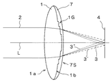
従来の技術として、例えば非特許文献1がある。ここではこの先例に基づき、これを簡略化して図6から図7を用いて説明する。図6は、従来例に於ける集光装置の断面構成を示している。集光装置1は、プラスチック等の透明媒質を材料にしたレンズ表面に鋸歯状の断面をなすグレーティング1Gを形成したもので、レンズ表面1a、1bは光軸Lを中心軸とする球面又は非球面であり、グレーティング1Gの方位はレンズ表面1b上で光軸Lを中心軸とする円周に沿っている。集光装置1に入射する光2はレンズ表面1aで屈折し、グレーティング1Gの付いたレンズ表面1bで屈折と回折(1次回折)が同時に発生し、検出面4上で集光する光3となる。
As a conventional technique, for example, there is Non-Patent
図7は、従来例に於ける集光装置の表面1bに於ける回折原理を説明する説明図であり、レンズ表面を平面にして説明している。屈折率nの透明基板1の表面1b上に形成された鋸歯状の断面をなすピッチΛのグレーティング1Gにより、波長λの光2は回折する。光2の入射角(面法線と為す角度)をゼロとすると(ゼロでなくても良いが簡単のためゼロとして説明する)、1次回折光3及び2次回折光3”の回折角度θ及びθ”(それぞれ面法線と為す角度)は、
sinθ=λ/Λ … (式1)
sinθ”=2λ/Λ … (式2)
で与えられる。当然、0次光3’は回折角度がゼロである。
FIG. 7 is an explanatory diagram for explaining the diffraction principle on the
sinθ = λ / Λ (Formula 1)
sinθ ″ = 2λ / Λ (Formula 2)
Given in. Naturally, the diffraction angle of the 0th-
一般には、0次光3’を挟んで反対側に−1次回折光や−2次回折光も発生するが、グレーティング断面を鋸歯状とすることで、−側の次数の回折光が弱められ、+側の次数の回折光が強められており、特にグレーティング断面の深さdが次式を満たすときに1次回折光3の回折効率は最大となる。
In general, −1st order diffracted light and −2nd order diffracted light are also generated on the opposite side across the
d=λ/(n−1) … (式3)
従って、深さdを最適化することで波長λの光が効率的に回折する。なお、グレーティング断面は鋸歯状でなくてもよく、鋸歯に内接する階段形状や単なる凹凸形状であっても良い。またピッチΛは一定値でなくてもよく、これを位置の関数とすることで回折角を調整し、回折光3を1点に集光する光とすることもできる。
Therefore, by optimizing the depth d, the light of wavelength λ is efficiently diffracted. Note that the grating cross-section does not have to be a sawtooth shape, and may have a stepped shape inscribed in the sawtooth or a simple uneven shape. Further, the pitch Λ does not have to be a constant value. By using this as a function of position, the diffraction angle can be adjusted and the
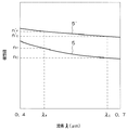
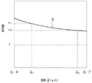
このような従来の集光装置及び回折装置において以下の問題があった。図8は従来例に於ける集光装置の透明基板1を構成する材料の分散特性(屈折率の波長依存特性)である。どのような光学材料でも可視光の領域では短波長に向かうに従って屈折率が単調増加する曲線5を描く。例えば、ゼオニックスの場合、C線(波長λC=0.6563μm)での屈折率nC=1.522983、F線(波長λF=0.4861μm)での屈折率nF=1.532271、ポリカーボネイトの場合、C線での屈折率nC=1.578401、F線での屈折率nF=1.597809である。
Such a conventional condensing device and diffraction device have the following problems. FIG. 8 is a dispersion characteristic (a wavelength dependence characteristic of a refractive index) of a material constituting the
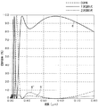
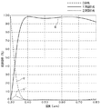
図9はグレーティング断面を一周期が16段の階段状とし、透明基板1を構成する材料をゼオニックスとし、深さd=0.95μmとした場合の波長に対する各回折光の回折効率を示している。1次回折光は波長0.53μm付近で極大になるが、0.53μm以外の波長では回折効率が低下する曲線6を描く。これは(式3)で示された回折効率最大の条件が波長と屈折率に依存する為である。例えば、波長が最適値(0.53μm)から小さくなると(式3)の右辺の分子は小さく分母は大きくなり、波長が大きくなると右辺の分子は大きく分母は小さくなるので、いずれも回折効率最大の条件からの乖離が屈折率変化(分母)、波長変化(分子)の両面から強められている。一方、1次回折光の効率低下と連動して、0次光や2次回折光の回折効率は波長が最適値(0.53μm)からずれるに従って増大する曲線6’、6”を描く。
FIG. 9 shows the diffraction efficiency of each diffracted light with respect to the wavelength when the grating cross-section is stepped with a period of 16 steps, the material constituting the
従って、図6で示した集光装置1では、特定の波長の光に対しては1次回折光3のみを検出面4上に集光させることができるが、それ以外の波長では0次光3’や2次回折光3”等が発生し、1次回折光3に対する迷光として作用する。特に集光装置1をカメラ用のレンズとして用いる場合には、これらの迷光の存在が再生像の劣化に繋がる。
Therefore, in the
本発明はかかる問題点に鑑み、広い波長領域に渡って高い1次回折光の効率を維持し、迷光の発生を抑えられる集光装置及び回折装置を提供することを目的とする。 In view of such problems, an object of the present invention is to provide a condensing device and a diffractive device capable of maintaining high efficiency of first-order diffracted light over a wide wavelength region and suppressing generation of stray light.
本発明の集光装置及び回折装置は、平面又は球面又は球面以外の面の上に周期的に形成された凹凸構造により透過光を回折させる透明媒質Aの表面に、前記媒質Aよりも高屈折率で低分散の透明媒質Bを充填することを特徴とする集光装置及び回折装置である。また、前記透明媒質Bの表面には透明媒質Aの表面の凹凸構造が残らないことを特徴とし、前記凹凸構造の断面は鋸歯状又は鋸歯に内接する階段状であることを特徴とする。更には、前記透明媒質A、Bの波長λに対する屈折率をnA、nB、波長λ’(<λ)に対する屈折率をnA’、nB’とすると、0.8<(nB−nA)/(nB’−nA’)×λ’/λ<1.2を満たすことを特徴とし、特に前記透明媒質A、BのC線(波長λ=0.6563μm)に対する屈折率をnA、nB、F線(波長λ’=0.4861μm)に対する屈折率をnA’、nB’とすると、(nB−nA)/(nB’−nA’)>1.05を満たすことを特徴とする。更には、前記透明媒質A、Bのe線(波長λ”=0.5461μm)に対する屈折率をnA”、nB”とすると、前記鋸歯状又は鋸歯に内接する階段状の断面の高低差dは0.8<(nB”−nA”)d/λ”<1.2の関係を満たすことを特徴とする。 The condensing device and the diffractive device of the present invention have a higher refraction than the medium A on the surface of the transparent medium A that diffracts the transmitted light by a concavo-convex structure periodically formed on a plane, a spherical surface, or a surface other than the spherical surface. A condensing device and a diffraction device, which are filled with a transparent medium B having a low dispersion rate. Further, the uneven structure of the surface of the transparent medium A does not remain on the surface of the transparent medium B, and the cross section of the uneven structure is a sawtooth shape or a step shape inscribed in the sawtooth. Further, when the refractive indexes of the transparent media A and B with respect to the wavelength λ are nA and nB, and the refractive indexes with respect to the wavelength λ ′ (<λ) are nA ′ and nB ′, 0.8 <(nB−nA) / ( nB′−nA ′) × λ ′ / λ <1.2. In particular, the refractive indexes of the transparent media A and B with respect to the C line (wavelength λ = 0.6563 μm) are expressed as nA, nB, and F line. When the refractive indexes with respect to (wavelength λ ′ = 0.4861 μm) are nA ′ and nB ′, (nB−nA) / (nB′−nA ′)> 1.05 is satisfied. Further, assuming that the refractive indexes of the transparent media A and B with respect to the e-line (wavelength λ ″ = 0.5461 μm) are nA ″ and nB ″, the height difference d of the sawtooth shape or the stepwise cross section inscribed in the sawtooth is It satisfies the relationship of 0.8 <(nB ″ −nA ″) d / λ ″ <1.2.
上記の様な構成により、分散による屈折率差の変化が波長の違いに伴う光学的な深さの変化を抑え、広い波長領域に渡って高い回折光の効率を維持でき、迷光の発生を抑えられる。 With the above configuration, the change in the refractive index difference due to dispersion suppresses the change in optical depth due to the difference in wavelength, maintains the efficiency of high diffracted light over a wide wavelength region, and suppresses the generation of stray light. It is done.
以上の本発明により、グレーティング付きの表面を高屈折率で低分散の透明材料で埋めることで、広い波長領域に渡って高い回折光の効率を維持し、迷光の発生を抑えることができる。 According to the present invention described above, by filling the surface with grating with a transparent material having a high refractive index and low dispersion, it is possible to maintain high efficiency of diffracted light over a wide wavelength region and to suppress generation of stray light.
(実施の形態1)
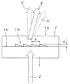
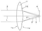
以下本発明の実施の形態を図1から図5に基づいて説明する。なお従来例と共通の要素については、同一の番号を振って説明する。図1は実施の形態に於ける集光装置の断面構成を示している。集光装置は屈折率と分散特性の異なる2種類のプラスチックや紫外線硬化樹脂等の透明媒質を材料にして構成され、第1の材料の構成部1はレンズ形状をなし、表面に鋸歯状の断面をなすグレーティング1Gを形成したもので、レンズ表面1a、1bは光軸Lを中心軸とする球面又は非球面であり、グレーティング1Gの方位はレンズ表面1b上で光軸Lを中心軸とする円周に沿っている。第2の材料の構成部7はグレーティング1Gの形成されたレンズ表面1bを覆い、その表面7Sはグレーティング1Gの凹凸形状が残らず、レンズ表面1bに沿った滑らかな形状をなす。なお、第2の材料は第1の材料よりも高屈折率で低分散である。
(Embodiment 1)
Hereinafter, embodiments of the present invention will be described with reference to FIGS. Elements common to the conventional example will be described with the same numbers. FIG. 1 shows a cross-sectional configuration of the light collecting device in the embodiment. The condensing device is composed of two types of transparent media such as plastic and ultraviolet curable resin having different refractive indexes and dispersion characteristics, and the
本実施の形態に於ける集光装置の形成の仕方は、例えば既にグレーティングの付いたレンズ形状に仕上がった第1の材料の構成部1を金型に押し込め、第1の材料の構成部1と金型との隙間に第2の材料を充填し、これを紫外線硬化させるなどの方法で第2の材料を固着させる方法等がある。
In the present embodiment, the condensing device is formed by, for example, pressing the
集光装置に入射する光2は構成部1の表面1aで屈折し、グレーティング1Gの付いた構成部1の表面1bで屈折と回折(1次回折)が同時に発生し、構成部2の表面7Sを透過、屈折して検出面4上に集光する光3となる。
The
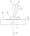
図2は本実施例に於ける集光装置の面1bに於ける回折原理を説明する説明図であり、面1bや他の面を平面にして説明している。透明基板1(構成部1)の屈折率をn、透明媒質7(構成部2)の屈折率をn’とし、面1b上に形成されたグレーティング1GをピッチΛの鋸歯状の断面とすると、波長λの光2はグレーティング1Gにより回折しするが、回折方位と鋸歯の方向との関係はn<n’のため従来例の反対になる。光2の入射角(面7S透過後の面法線と為す角度)をゼロとすると(ゼロでなくても良いが簡単のためゼロとして説明する)、1次回折光3及び2次回折光3”の回折角度θ及びθ”(それぞれ面7S透過後の面法線と為す角度)は前述の(式1)、(式2)で与えられる。当然、0次光3’は回折角度がゼロである。
FIG. 2 is an explanatory diagram for explaining the principle of diffraction on the
一般には、0次光3’を挟んで反対側に−1次回折光や−2次回折光も発生するが、グレーティング断面を鋸歯状とすることで、−側の次数の回折光が弱められ、+側の次数の回折光が強められており、特にグレーティング断面の深さdが、
d=λ/(n’−n) … (式4)
を満たすときに1次回折光3の回折効率は最大となる。従って、深さdを最適化することで波長λの光が効率的に回折する。
In general, −1st order diffracted light and −2nd order diffracted light are also generated on the opposite side across the
d = λ / (n′−n) (Formula 4)
The diffraction efficiency of the first-order diffracted
なお、グレーティング断面は鋸歯状でなくてもよく、鋸歯に内接する階段形状や単なる凹凸形状であっても良い。またピッチΛは一定値でなくてもよく、これを位置の関数とすることで回折角を調整し、回折光3を1点に集光する光とすることもできる。
Note that the grating cross-section does not have to be a sawtooth shape, and may be a stepped shape inscribed in the sawtooth or a simple uneven shape. The pitch Λ does not have to be a constant value. By using this as a function of position, the diffraction angle can be adjusted, and the diffracted
図3は、本実施形態に於ける集光装置の透明基板1(第1の材料)及び透明媒質7(第2の材料)を構成する材料の分散特性(屈折率の波長依存特性)である。第1の材料は短波長に向かうに従って屈折率が単調増加する曲線5を描き、第2の材料も短波長に向かうに従って屈折率が単調増加する曲線5’を描くが、第2の材料は第1の材料よりも高屈折率で低分散である。即ち、第1の材料、第2の材料のC線での屈折率をnC及びnC’、F線での屈折率をnF及びnF’とすると、
nF’>nF かつ nC’>nC … (式5)
(nC’−nC)/(nF’−nF)>1 … (式6)
が成り立つ。
FIG. 3 is a dispersion characteristic (a wavelength dependency characteristic of a refractive index) of a material constituting the transparent substrate 1 (first material) and the transparent medium 7 (second material) of the light collecting device in the present embodiment. . The first material draws a
nF ′> nF and nC ′> nC (Formula 5)
(NC′−nC) / (nF′−nF)> 1 (Formula 6)
Holds.
図4はグレーティング断面を一周期が16段の階段状とし、透明基板1を構成する材料をゼオニックスとし、透明媒質7を構成する材料を屈折率1.68で分散がゼロの材料とし、深さd=3.5μmとした場合の波長に対する各回折光の回折効率を示している。実際には分散がゼロの材料は世の中に存在しないが、透明基板1に比べ透明媒質7の分散が十分小さい一例として説明する。
In FIG. 4, the grating cross section has a stepped shape with a period of 16 steps, the material constituting the
1次回折光は波長0.57μm付近で極大になり、0.57μm以外の波長では回折効率が低下する曲線6を描くが、低下の度合いは従来例に比べ大幅に改善され、0次光や2次回折光の回折効率の増大(それぞれ曲線6’、6”参照)も抑えられている。これは波長の変化に伴って発生する(式4)で示された回折効率最大の条件からの乖離が、透明基板1、透明媒質7の分散特性によって緩和される為である。即ち、波長が最適値(0.57μm)から小さくなると(式4)の右辺の分子は小さくなるが分母も小さくなり、波長が大きくなると右辺の分子は大きくなるが分母も大きくなるので、いずれも回折効率最大の条件からの乖離が弱められている。
The 1st-order diffracted light becomes a maximum near the wavelength of 0.57 μm, and a
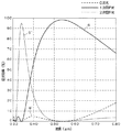
図5はグレーティング断面を一周期が16段の階段状とし、透明基板1を構成する材料をポリカーボネイトとし、透明媒質7を構成する材料を屈折率1.68で分散がゼロの材料とし、深さd=6.0μmとした場合の波長に対する各回折光の回折効率を示している。1次回折光は可視光領域全般に渡って95%以上を維持できており(曲線6)、0次光や2次回折光の回折効率も1%以下のレベルである(曲線6’、6”)。図5では図4の例以上の改善効果が得られている。
In FIG. 5, the grating cross section has a stepped shape with a period of 16 steps, the material constituting the
この改善効果の度合いは、(nC’−nC)/(nF’−nF)の値に関係する。例えば、図4の条件では(nC’−nC)/(nF’−nF)=(1.68−1.522983)/(1.68−1.532271)=1.0628、図5の条件では(nC’−nC)/(nF’−nF)=(1.68−1.578401)/(1.68−1.597809)=1.236となり、更には(nC’−nC)/(nF’−nF)=λC/λF=0.6563/0.4861=1.35であれば、ほぼ完全に可視光領域全般で回折効率最大の条件を満たすことができる。 The degree of this improvement effect is related to the value of (nC′−nC) / (nF′−nF). For example, in the condition of FIG. 4, (nC′−nC) / (nF′−nF) = (1.68−1.522983) / (1.68−1.532271) = 1.0628, and in the condition of FIG. (NC′−nC) / (nF′−nF) = (1.68−1.578401) / (1.68−1.597809) = 1.236, and (nC′−nC) / (nF If '−nF) = λC / λF = 0.6563 / 0.4861 = 1.35, the maximum diffraction efficiency condition can be satisfied almost entirely in the visible light region.
なお、グレーティング断面の深さdは、可視光領域の中間よりも青よりの波長域で(式4)を満足させるほうが、可視光領域全域での1次回折効率維持に繋がり、図4、図5のd(=3.5μm、6.0μm)はそれぞれ波長λ=0.53μm、及び波長λ=0.54μmでの(式4)の計算結果である。 Note that the depth d of the grating cross section satisfies (Equation 4) in the wavelength range of blue rather than in the middle of the visible light region, which leads to maintaining the first-order diffraction efficiency in the entire visible light region. 5 d (= 3.5 μm, 6.0 μm) are the calculation results of (Expression 4) at the wavelength λ = 0.53 μm and the wavelength λ = 0.54 μm, respectively.
本実施例は従来例に比べて、透明媒質7を付加する等、構造が複雑になるデメリットがあるが、一つの目安として
0.8<(nC’−nC)/(nF’−nF)×λF/λC<1.2 … (式5)
或いは
(nC’−nC)/(nF’−nF)>1.05 … (式6)
等を満足できれば、迷光の発生が抑えられるメリットの方がデメリットを越える。当然、F線、C線は他の波長であってもよく、必要な波長帯域の長波長側の代表を添字C、短波長側の代表をFとして(式5)又は(式6)が成り立てば、その波長帯域全般での1次回折効率を高く維持でき、迷光の発生を抑えることができる。
Compared with the conventional example, this example has a demerit that the structure becomes complicated, such as adding a
Or (nC′−nC) / (nF′−nF)> 1.05 (Formula 6)
If the above conditions are satisfied, the advantage of suppressing the generation of stray light exceeds the disadvantage. Naturally, the F-line and the C-line may have other wavelengths, and the long wavelength side representative of the necessary wavelength band is subscript C, and the short wavelength side representative is F, and (Formula 5) or (Formula 6) is established. For example, the first-order diffraction efficiency in the entire wavelength band can be maintained high, and stray light generation can be suppressed.
なお、上記実施形態では集光装置として説明したが、集光機能がない一般的な回折装置であってもよい。また、1次回折効率に注目し、これを高く維持する視点で説明したが、欲しい回折光が2次回折光や高次回折光であってもよく、同様の効果が得られる。 In the above embodiment, the light collecting device has been described. However, a general diffraction device having no light collecting function may be used. Further, the first-order diffraction efficiency has been described from the viewpoint of keeping this high, but the desired diffracted light may be second-order diffracted light or higher-order diffracted light, and the same effect can be obtained.
本発明の集光装置は、例えばカメラのレンズ等として用いることができる。 The condensing device of the present invention can be used as a lens of a camera, for example.
1 第1の材料の構成部
1G グレーティング
1a,1b 第1の材料の構成部の表面
7 第2の材料の構成部
2 入射光
3 1次回折光
3’ 0次光
3” 2次回折光
4 検出面
L 光軸
DESCRIPTION OF
Claims (6)
Priority Applications (1)
| Application Number | Priority Date | Filing Date | Title |
|---|---|---|---|
| JP2004103772A JP2005292244A (en) | 2004-03-31 | 2004-03-31 | Condensing device and diffraction device |
Applications Claiming Priority (1)
| Application Number | Priority Date | Filing Date | Title |
|---|---|---|---|
| JP2004103772A JP2005292244A (en) | 2004-03-31 | 2004-03-31 | Condensing device and diffraction device |
Publications (1)
| Publication Number | Publication Date |
|---|---|
| JP2005292244A true JP2005292244A (en) | 2005-10-20 |
Family
ID=35325276
Family Applications (1)
| Application Number | Title | Priority Date | Filing Date |
|---|---|---|---|
| JP2004103772A Pending JP2005292244A (en) | 2004-03-31 | 2004-03-31 | Condensing device and diffraction device |
Country Status (1)
| Country | Link |
|---|---|
| JP (1) | JP2005292244A (en) |
Cited By (2)
| Publication number | Priority date | Publication date | Assignee | Title |
|---|---|---|---|---|
| EP1619678A4 (en) * | 2003-04-25 | 2007-04-04 | Asahi Glass Co Ltd | DIFFRACTION ELEMENT AND OPTICAL HEAD DEVICE |
| WO2014073199A1 (en) * | 2012-11-07 | 2014-05-15 | パナソニック株式会社 | Diffraction-grating lens, and image-capturing optical system and image-capturing device using said lens |
-
2004
- 2004-03-31 JP JP2004103772A patent/JP2005292244A/en active Pending
Cited By (3)
| Publication number | Priority date | Publication date | Assignee | Title |
|---|---|---|---|---|
| EP1619678A4 (en) * | 2003-04-25 | 2007-04-04 | Asahi Glass Co Ltd | DIFFRACTION ELEMENT AND OPTICAL HEAD DEVICE |
| WO2014073199A1 (en) * | 2012-11-07 | 2014-05-15 | パナソニック株式会社 | Diffraction-grating lens, and image-capturing optical system and image-capturing device using said lens |
| JP2014095739A (en) * | 2012-11-07 | 2014-05-22 | Panasonic Corp | Diffraction grating lens, imaging optical system using the same and imaging apparatus |
Similar Documents
| Publication | Publication Date | Title |
|---|---|---|
| JP5264223B2 (en) | Diffractive optical element, optical system and optical instrument | |
| JP3472097B2 (en) | Diffractive optical element and optical system using the same | |
| JP5132284B2 (en) | Diffractive optical element, optical system having the same, and optical instrument | |
| JP5137432B2 (en) | Adherent two-layer type diffractive optical element and optical system and optical apparatus using the same | |
| JP3472103B2 (en) | Diffractive optical element and optical system using the same | |
| JP4977275B2 (en) | Diffraction grating lens and imaging device using the same | |
| US7236302B2 (en) | Diffraction optical element | |
| JP2005107298A (en) | Diffractive optical element and method of manufacturing diffractive optical element | |
| JP5258204B2 (en) | Diffractive optical element, optical system using the same, and optical instrument | |
| JP4714152B2 (en) | Optical element | |
| JP2008242390A (en) | Diffractive optical element and optical system having the same | |
| JP4387855B2 (en) | Optical system | |
| CN104813200A (en) | Diffraction-grating lens, and image-capturing optical system and image-capturing device using said lens | |
| JP2011022255A (en) | Diffraction optical element and optical system having the same | |
| JP2004078166A (en) | Diffractive optical element and optical system having the same | |
| JP3472154B2 (en) | Diffractive optical element and optical system having the same | |
| US6930833B2 (en) | Diffractive optical element, and optical system and optical apparatus provide with the same | |
| JP2013125259A (en) | Diffractive optical element, optical system, and optical apparatus | |
| JP5765998B2 (en) | Diffractive optical element, optical system and optical instrument | |
| JP2002082214A (en) | Diffractive optical element and optical system using the same | |
| JP3860261B2 (en) | Diffractive optical element having diffractive surfaces on both sides | |
| JP2005292244A (en) | Condensing device and diffraction device | |
| US8451538B2 (en) | Diffractive optical element and optical device | |
| JP4743607B2 (en) | Fresnel lens and liquid crystal projector using the Fresnel lens | |
| US8508847B2 (en) | Diffractive optical element and optical device |