JP2005292078A - Incremental type displacement measuring instrument - Google Patents
Incremental type displacement measuring instrument Download PDFInfo
- Publication number
- JP2005292078A JP2005292078A JP2004111070A JP2004111070A JP2005292078A JP 2005292078 A JP2005292078 A JP 2005292078A JP 2004111070 A JP2004111070 A JP 2004111070A JP 2004111070 A JP2004111070 A JP 2004111070A JP 2005292078 A JP2005292078 A JP 2005292078A
- Authority
- JP
- Japan
- Prior art keywords
- reference signal
- main
- signal
- scale
- incremental
- Prior art date
- Legal status (The legal status is an assumption and is not a legal conclusion. Google has not performed a legal analysis and makes no representation as to the accuracy of the status listed.)
- Pending
Links
- 238000006073 displacement reaction Methods 0.000 title claims abstract description 58
- 230000003287 optical effect Effects 0.000 claims abstract description 59
- 238000005259 measurement Methods 0.000 claims abstract description 56
- 230000007274 generation of a signal involved in cell-cell signaling Effects 0.000 claims description 16
- 230000001360 synchronised effect Effects 0.000 claims description 7
- 230000001960 triggered effect Effects 0.000 claims description 6
- 238000010586 diagram Methods 0.000 description 13
- 230000000630 rising effect Effects 0.000 description 11
- 238000012986 modification Methods 0.000 description 6
- 230000004048 modification Effects 0.000 description 6
- 238000012545 processing Methods 0.000 description 4
- 230000001678 irradiating effect Effects 0.000 description 3
- 230000015572 biosynthetic process Effects 0.000 description 2
- 230000000052 comparative effect Effects 0.000 description 2
- 239000011521 glass Substances 0.000 description 2
- 238000000034 method Methods 0.000 description 2
- 238000003786 synthesis reaction Methods 0.000 description 2
- 230000002194 synthesizing effect Effects 0.000 description 2
- 239000012780 transparent material Substances 0.000 description 2
- 230000005540 biological transmission Effects 0.000 description 1
- 238000001514 detection method Methods 0.000 description 1
- 230000005674 electromagnetic induction Effects 0.000 description 1
- 230000006870 function Effects 0.000 description 1
- 238000003780 insertion Methods 0.000 description 1
- 230000037431 insertion Effects 0.000 description 1
- 238000004519 manufacturing process Methods 0.000 description 1
Images


Landscapes
- Optical Transform (AREA)
Abstract
Description
本発明は、インクリメンタル型変位測定装置に係り、例えばゼロセットやプリセットの機能の改良に関する。 The present invention relates to an incremental-type displacement measuring apparatus, and relates to, for example, improvement of zero set and preset functions.
従来から直線変位等の精密な測定に、エンコーダのような変位測定装置が利用されている。変位測定装置の方式には、光学式、電磁誘導式、静電容量式等がある。光学式で説明すると光学式エンコーダは、例えば、光学格子が設けられたメインスケール及びこのスケール上を移動可能なセンサヘッドを備える。センサヘッドには、メインスケールと対向して配置されると共に光学格子が設けられたインデックススケールと、発光ダイオードを有する光源と、フォトダイオードを有する受光部と、が含まれる。 Conventionally, a displacement measuring device such as an encoder has been used for precise measurement such as linear displacement. As a method of the displacement measuring device, there are an optical type, an electromagnetic induction type, a capacitance type, and the like. The optical encoder includes, for example, a main scale provided with an optical grating and a sensor head that can move on the scale. The sensor head includes an index scale that is arranged opposite to the main scale and provided with an optical grating, a light source having a light emitting diode, and a light receiving unit having a photodiode.
発光ダイオードを点灯させた状態でセンサヘッドを移動させると、メインスケールに設けられた光学格子とインデックススケールに設けられた光学格子とにより光の明暗パターンが生成される。この明暗パターンをフォトダイオードで検出して電気信号に変換し、この信号を基にして変位量を算出する。 When the sensor head is moved in a state where the light-emitting diode is turned on, a light / dark pattern of light is generated by the optical grating provided on the main scale and the optical grating provided on the index scale. This light / dark pattern is detected by a photodiode and converted into an electrical signal, and the amount of displacement is calculated based on this signal.
変位測定装置のうちインクリメンタル型は、上記電気信号(主信号)を内挿処理等して生成されたパルスをカウントすることにより変位量を測定する。このため、センサヘッドをメインスケール上の原点を通過させて、原点を検出してからでなければ測定を開始できない。この原点を検出する操作を原点取りという。 Of the displacement measuring devices, the incremental type measures the amount of displacement by counting pulses generated by interpolating the electric signal (main signal). For this reason, the measurement can be started only after the sensor head is passed through the origin on the main scale and the origin is detected. This operation of detecting the origin is called origin retrieval.
センサヘッドは、往き方向及びこれと逆の戻り方向にメインスケール上を移動することが可能であるが、片方の方向からしか原点取りができないエンコーダがある(特許文献1)。例えば、往き方向からしか原点取りができない場合、センサヘッドを往き方向に動かしてメインスケール上の原点を通過させなければ、測定を開始できない。
往き方向及び戻り方向の両方から原点取り(以下、「インクリメンタル測定の基準位置取り」という。)ができれば便利である。しかし、往き方向と戻り方向とで原点の検出にずれが生じると、往き方向から測定した場合と戻り方向から測定した場合とで変位量が異なるという不都合が生じる。 It is convenient if the origin can be obtained from both the forward direction and the return direction (hereinafter referred to as “reference position acquisition of incremental measurement”). However, if there is a difference in the detection of the origin between the forward direction and the return direction, there is a disadvantage that the amount of displacement differs between when measured from the forward direction and when measured from the return direction.
本発明は、インクリメンタル測定の基準位置取りを、一方の方向からした場合とこれと逆の他方の方向からした場合とで基準位置を揃えることが可能なインクリメンタル型変位測定装置を提供することを目的とする。 An object of the present invention is to provide an incremental displacement measuring apparatus capable of aligning a reference position in a case where the reference position of the incremental measurement is taken from one direction and the other direction opposite thereto. And
本発明に係るインクリメンタル型変位測定装置の一態様は、メインスケールと、一方の方向及びこれと逆の他方の方向に測定軸に沿って前記メインスケールに対して相対移動可能であると共に前記メインスケールと対向して配置されたインデックススケールと、前記メインスケール及び前記インデックススケールに設けられると共にインクリメンタル測定のカウント用のパルスの基になる主信号を生成するための主信号用光学格子と、前記メインスケール及び前記インデックススケールに設けられると共に前記インクリメンタル測定における基準位置の特定用の参照信号を生成するための参照信号用光学格子と、前記メインスケールに対する前記インデックススケールの相対移動により、前記参照信号用光学格子を基にして主信号と非同期の参照信号である第1参照信号を生成する第1参照信号生成回路と、前記一方の方向と前記他方の方向とでアクティブとなる位置が異なる参照信号である第2参照信号を第1参照信号のアクティブ中に主信号と同期するように生成する第2参照信号生成回路と、第2参照信号と同期すると共に第2参照信号がアクティブになるよりも遅れてアクティブとなる参照信号である第3参照信号を生成する第3参照信号生成回路と、主信号を基に生成された前記インクリメンタル測定のカウント用のパルスの数をカウントすると共に前記インクリメンタル測定の基準位置を示す基準値のセットのトリガが前記一方の方向から変位を測定する場合は第2又は第3参照信号であり、前記他方の方向から変位を測定する場合は第3参照信号であるカウンタ回路と、を備えることを特徴とする。 One aspect of the incremental displacement measuring apparatus according to the present invention is a main scale, and is movable relative to the main scale along a measurement axis in one direction and the other direction opposite to the main scale. An index scale disposed opposite to the main scale, an optical grating for main signal provided on the main scale and the index scale, and for generating a main signal as a basis of a pulse for counting for incremental measurement, and the main scale A reference signal optical grating for generating a reference signal for specifying a reference position in the incremental measurement, and the reference signal optical grating by relative movement of the index scale with respect to the main scale. Based on the main signal and asynchronous A first reference signal generation circuit that generates a first reference signal that is a reference signal, and a second reference signal that is a reference signal that is active in different directions in the one direction and the other direction. A second reference signal generation circuit that generates the active signal so as to be synchronized with the main signal, and a third reference that is synchronized with the second reference signal and is activated later than the second reference signal becomes active A third reference signal generation circuit for generating a signal, and a trigger for setting a reference value for counting the number of pulses for counting the incremental measurement generated based on a main signal and indicating a reference position for the incremental measurement, A counter circuit that is a second or third reference signal when measuring displacement from one direction and a third reference signal when measuring displacement from the other direction , Characterized in that it comprises a.
本発明の一態様によれば、カウンタ回路の基準値セットのトリガを、一方の方向の場合は第2又は第3参照信号とし、他方の方向の場合は第3参照信号にしている。第3参照信号は、第2参照信号がアクティブになるよりも遅れてアクティブとなるので、一方の方向と他方の方向とで基準位置を揃えることが可能となる。 According to one aspect of the present invention, the trigger of the reference value set of the counter circuit is the second or third reference signal in one direction and the third reference signal in the other direction. Since the third reference signal becomes active after the second reference signal becomes active, the reference positions can be aligned in one direction and the other direction.
本発明の一態様において、前記一方の方向から変位を測定する場合、第2参照信号が前記基準値のセットのトリガとなり、第2参照信号をトリガとした場合における前記一方の方向の前記基準値セットの位置と前記他方の方向の前記基準値セットの位置との間のカウント数を予め求めておき、このカウント数を基にして第3参照信号の遅れを設定する、ようにすることができる。さらに具体的には、第2参照信号がトリガになると共に第3参照信号の遅れに相当する数をカウントするとアクティブの第3参照信号を出力するUP/DOWNカウンタを備えるようにすることができる。これによれば、基準位置取り中に、振動等が原因でインデックススケールの相対移動の方向が逆の方向に変わっても、その影響をなくすことができる。 In one aspect of the present invention, when measuring displacement from the one direction, the second reference signal serves as a trigger for the set of reference values, and the reference value in the one direction when the second reference signal is used as a trigger. A count number between the position of the set and the position of the reference value set in the other direction is obtained in advance, and the delay of the third reference signal can be set based on this count number. . More specifically, an UP / DOWN counter that outputs an active third reference signal when the second reference signal is triggered and a number corresponding to the delay of the third reference signal is counted can be provided. According to this, even if the relative movement direction of the index scale is changed to the opposite direction due to vibration or the like during the reference position setting, the influence can be eliminated.
本発明に係るインクリメンタル型変位測定装置の他の態様は、メインスケールと、一方の方向及びこれと逆の他方の方向に測定軸に沿って前記メインスケールに対して相対移動可能であると共に前記メインスケールと対向して配置されたインデックススケールと、前記メインスケール及び前記インデックススケールに設けられると共にインクリメンタル測定のカウント用のパルスの基になる主信号を生成するための主信号用光学格子と、前記メインスケール及び前記インデックススケールに設けられると共に前記インクリメンタル測定における基準位置の特定用の参照信号を生成するための参照信号用光学格子と、前記メインスケールに対する前記インデックススケールの相対移動により、前記参照信号用光学格子を基にして主信号と非同期の参照信号である第1参照信号を生成する第1参照信号生成回路と、前記一方の方向と前記他方の方向とでアクティブとなる位置が異なる参照信号である第2参照信号を第1参照信号のアクティブ中に主信号と同期するように生成する第2参照信号生成回路と、主信号を基に生成された前記インクリメンタル測定のカウント用のパルスの数をカウントすると共に第2参照信号をトリガにして初期値がセットされるカウンタ回路と、を備え、前記一方の方向から変位を測定する場合の前記初期値は、前記インクリメンタル測定の基準位置を示す基準値又は前記基準値から後戻りした値であり、前記他方の方向から変位を測定する場合の前記初期値は、前記基準値から後戻りした値である、ことを特徴とする。 In another aspect of the incremental displacement measuring apparatus according to the present invention, the main scale is movable relative to the main scale along the measurement axis in one direction and the other direction opposite to the main scale. An index scale disposed opposite to the scale; a main signal optical grating provided on the main scale and the index scale and generating a main signal as a basis of pulses for counting for incremental measurement; and the main scale A reference signal optical grating provided on the scale and the index scale and for generating a reference signal for specifying a reference position in the incremental measurement, and the reference signal optical by relative movement of the index scale with respect to the main scale. Asynchronous with main signal based on lattice A first reference signal generation circuit that generates a first reference signal that is a reference signal, and a second reference signal that is a reference signal that is active at different positions in the one direction and the other direction, A second reference signal generation circuit that is generated so as to be synchronized with the main signal during active, and counts the number of pulses for counting the incremental measurement generated based on the main signal, and the second reference signal is used as a trigger. A counter circuit in which an initial value is set, and when the displacement is measured from the one direction, the initial value is a reference value indicating a reference position of the incremental measurement or a value reverted from the reference value, The initial value when the displacement is measured from the other direction is a value that is reversed from the reference value.
本発明の他の態様によれば、カウンタ回路にセットされる初期値を、一方の方向の場合は基準値又はこれより後戻りした値とし、他方の方向の場合は基準値より後戻りした値にしている。このため、一方の方向と他方の方向とで基準位置を揃えることが可能となる。 According to another aspect of the present invention, the initial value set in the counter circuit is a reference value in one direction or a value back from this, and a value back from the reference value in the other direction. Yes. For this reason, it is possible to align the reference positions in one direction and the other direction.
本発明の他の態様において、前記一方の方向から変位を測定する場合の前記初期値は前記基準値であり、前記他方の方向から変位を測定する場合の前記初期値である前記後戻りした値は、前記一方の方向のトリガ発生と前記他方の方向のトリガ発生との間の予め求められていたカウント数を基にして設定される、ようにすることができる。 In another aspect of the invention, the initial value when the displacement is measured from the one direction is the reference value, and the backward value that is the initial value when the displacement is measured from the other direction is In this case, it is set based on a count number obtained in advance between the trigger occurrence in the one direction and the trigger occurrence in the other direction.
本発明の一態様及び他の態様において、前記メインスケール及び前記インデックススケールを部品として組み立てられたアセンブリと、前記カウンタ回路が組み込まれると共に前記アセンブリとケーブルにより接続可能なカウント装置と、を備える、ようにすることができる。また、前記メインスケール及び前記インデックススケールを部品として組み立てられたアセンブリに、前記カウンタ回路が組み込まれている、ようにすることもできる。 In one aspect and another aspect of the present invention, an assembly assembled with the main scale and the index scale as parts, and a counter device in which the counter circuit is incorporated and connected to the assembly by a cable, Can be. In addition, the counter circuit may be incorporated in an assembly in which the main scale and the index scale are assembled as parts.
本発明に係るインクリメンタル型変位測定装置によれば、インクリメンタル測定の基準位置取りを一方の方向からした場合とこれと逆の他方の方向からした場合とで基準位置を揃えること、つまり基準位置を同じにすることが可能となる。したがって、基準位置取りの操作を片方の方向からに制限する必要がないため、測定の利便性を向上させることができる。 According to the incremental displacement measuring apparatus of the present invention, the reference position is aligned between the case where the reference position of the incremental measurement is taken from one direction and the other direction opposite thereto, that is, the reference position is the same. It becomes possible to. Therefore, it is not necessary to restrict the reference positioning operation from one direction, and the convenience of measurement can be improved.
以下、図面を参照して、本実施形態に係るインクリメンタル型変位測定装置(「変位測定装置」と記載する場合もある。)について説明する。なお、図において、既に説明した図中の符号で示すものと同一のものについては、同一符号を付すことにより説明を省略する。 Hereinafter, an incremental displacement measuring apparatus (sometimes referred to as “displacement measuring apparatus”) according to the present embodiment will be described with reference to the drawings. In the figure, the same reference numerals are used to designate the same elements as those shown in the drawings already described, and the description thereof is omitted.
まず、本明細書で用いられる基準位置及び基準値について説明する。原点取りにはゼロセットとプリセットがある。ゼロセットは、任意の位置で表示値をゼロにすることである。プリセットは、表示部に任意の数値をセットすることである。したがって、ゼロセットはゼロを原点とし、プリセットは上記任意の数値を原点として測定が開始される。このように原点取りにおける原点は必ずしもゼロではないので、本明細書では、「原点」の替りに、「インクリメンタル測定における基準位置」という表現を用い、「原点取り」の替わりに「基準位置取り」という表現を用いる。基準位置に対応する値が基準値であり、ゼロセットではゼロ、プリセットでは上記任意の数値が、それぞれ基準値となる。
[第1実施形態]
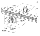
図1は、第1実施形態に係る光学式のインクリメンタル型変位測定装置1の概略構成を示す斜視図である。変位測定装置1の具体例としては、例えばリニヤスケール、リニヤゲージ、デジタル表示付ダイヤルゲージがある。変位測定装置1は、装置1の測定軸Xに沿って延びた長尺状のメインスケール3と、スケール3に対して往き方向(一方の方向の一例)及びこれと逆の戻り方向(他方の方向の一例)に測定軸Xに沿って移動可能なセンサヘッド5と、を備える。
First, reference positions and reference values used in this specification will be described. There are zero set and preset for the origin. Zero set is to make the display value zero at an arbitrary position. The preset is to set an arbitrary numerical value on the display unit. Accordingly, measurement is started with zero set as the origin and zero as the preset with the above-mentioned arbitrary numerical value as the origin. As described above, since the origin in the origin determination is not necessarily zero, in this specification, the expression “reference position in incremental measurement” is used instead of “origin”, and “reference position acquisition” is used instead of “origin acquisition”. The expression is used. A value corresponding to the reference position is a reference value, and zero in the zero set and the above arbitrary numerical value in the preset are the reference values.
[First Embodiment]
FIG. 1 is a perspective view showing a schematic configuration of an optical incremental
メインスケール3は、ガラス等の透明材料で構成される。スケール3には、所定ピッチの光学格子7(主信号用光学格子の一例)がスケール3の長手方向に沿って形成されている。また、スケール3のインクリメンタル測定における基準位置には、光学格子9(参照信号用光学格子の一例)が形成されている。
The
センサヘッド5は、メインスケール3の一方の面側に、スケール3と対向するように配置されたインデックススケール11を備える。スケール11はセンサヘッド5に配置されているため、往き方向及び戻り方向に測定軸Xに沿ってメインスケール3上を移動可能となる。スケール11は、ガラス等の透明材料で構成される。スケール11には、光学格子7と同じピッチの四つの光学格子13(主信号用光学格子の一例)が光学格子7と対向するように形成されている。
The
光学格子13aの位相空間を0度とすると、光学格子13bの位相空間が90度、光学格子13aaの位相空間が180度、光学格子13bbの位相空間が270度となるように、これらの格子のピッチが規定されている。また、スケール11には、メインスケール3の光学格子9と対応する光学格子15(参照信号用光学格子の一例)が形成されている。
When the phase space of the
センサヘッド5は、スケール3,11を挟んで互いに向かい合うように配置された光源17と受光部19を備えている。光源17は発光ダイオードを含み、メインスケール3側に配置されている。受光部19はインデックススケール11側に配置されている。受光部19は、四つのフォトダイオード21及び一つのフォトダイオード23により構成される。ダイオード21a,21b,21aa,21bbは、それぞれ、光学格子13a,13b,13aa,13bbと対向している。また、ダイオード23はインデックススケール11の光学格子15と対向している。
The
さて、光源17からの光Lがメインスケール3を介してインデックススケール11に照射された状態で、センサヘッド5を測定軸Xに沿ってメインスケール3上を移動させることにより、変位の測定が実行される。このとき、光Lが光学格子7及び光学格子13aに照射されることにより生成された正弦波状の光の明暗パターンは、フォトダイオード21aで受光され、主信号φaとして出力される。
Now, measurement of displacement is performed by moving the
同様に、光Lが光学格子7及び光学格子13b(13aa,13bb)に照射されることにより生成された正弦波状の光の明暗パターンは、ダイオード21b(21aa,21bb)で受光され、主信号φb(φaa,φbb)として出力される。また、光Lが光学格子9及び光学格子15に照射されることにより生成された光の明暗パターンは、フォトダイオード23で受光され、参照信号φrとして出力される。
Similarly, a light / dark pattern of sinusoidal light generated by irradiating the light L onto the
主信号は、インクリメンタル測定のカウント用のパルスの基になる信号であり、光学格子7,13(主信号用光学格子の一例)を利用して生成される。パルス数から変位量が演算される。主信号φaはa相(0度)の信号である。主信号φbはa相より90度だけ位相がずれたb相(90度)の信号であり、主信号φaaはa相より180度だけ位相がずれたaa相(180度)の信号であり、主信号φbbはa相より270度だけ位相がずれたbb相(270度)の信号である。
The main signal is a signal that is a basis of a pulse for counting the incremental measurement, and is generated using the
a相及びb相の信号を利用するのは、これらのどちらが相手に対して90°進んでいるかによって、センサヘッド5の移動方向が往き方向か戻り方向かを判断するためである。また、a相やb相以外にこれらを反転させた、aa相やbb相を利用するのは、a相やb相の信号に含まれる直流成分の除去、並びに、信号の信頼性及び高速追従性の確保のためである。
The reason why the a-phase and b-phase signals are used is to determine whether the moving direction of the
参照信号は、インクリメンタル測定における基準位置の特定用の信号であり、光学格子9,15(参照信号用光学格子の一例)を利用して生成される。参照信号のうち参照信号φrは、メインスケール3に対するインデックススケール11の相対移動により、光学格子9,15を基にして主信号と非同期に生成される信号である。
The reference signal is a signal for specifying the reference position in the incremental measurement, and is generated by using the
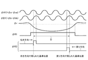
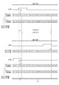
図2は主信号及び参照信号の波形図である。主信号φA1は主信号φaと主信号φaaを合成した正弦波状の信号である。また、主信号φB1は主信号φbと主信号φbbを合成した正弦波状の信号であり、主信号φA1と位相が90度ずれている。 FIG. 2 is a waveform diagram of the main signal and the reference signal. The main signal φA1 is a sinusoidal signal obtained by synthesizing the main signal φa and the main signal φaa. The main signal φB1 is a sinusoidal signal obtained by synthesizing the main signal φb and the main signal φbb, and is 90 degrees out of phase with the main signal φA1.
参照信号φR1(第1参照信号の一例)は、参照信号φrが二値化処理された信号である。信号φR1も信号φrと同様に、メインスケール3に対するインデックススケール11の相対移動により、光学格子9,15を基にして主信号と非同期に生成される信号である。
The reference signal φR1 (an example of the first reference signal) is a signal obtained by binarizing the reference signal φr. Similarly to the signal φr, the signal φR1 is a signal generated asynchronously with the main signal based on the
参照信号φR2(第2参照信号の一例)は、参照信号φR1のアクティブ中に主信号φA1,φB1と同期するように生成される信号である。詳しくは、信号φR2は、信号φR1がアクティブになった後(立ち上がった後)、主信号φA1,φB1のいずれかが最初に最大値になった時にアクティブとなり(立ち上り)、次に最大値になった時にノンアクティブとなる(立ち下がる)。 Reference signal φR2 (an example of a second reference signal) is a signal generated so as to be synchronized with main signals φA1 and φB1 while reference signal φR1 is active. Specifically, the signal φR2 becomes active (rising) when one of the main signals φA1 and φB1 first reaches the maximum value after the signal φR1 becomes active (after rising), and then becomes the maximum value. Becomes inactive (falls) when
参照信号φr,φR1,φR2は、図1のメインスケール3の光学格子9上をインデックススケール11の光学格子15が通過することにより得られる信号である。参照信号は、インクリメンタル型の変位測定装置において、電源投入時や任意の時点でインクリメンタル測定における基準位置取りをする際のトリガとして主に利用される。つまり、主信号を基に生成されたパルスの数をカウントするカウンタ回路に、基準位置を示す基準値(例えばゼロセットの場合はゼロ)をセットする際のトリガとして参照信号が用いられる。
The reference signals φr, φR1, and φR2 are signals obtained when the
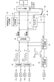
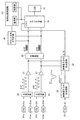
次に、変位測定装置1に備えられる回路部のブロックについて説明する。図3はこれを示すブロック図である。主信号φaと主信号φaaは合成回路25に入力して合成処理されて、主信号φA1として出力される。同様に、主信号φbと主信号φbbは主信号φB1として出力される。
Next, the block of the circuit unit provided in the
これら2相の正弦波からなる主信号φA1,φB1はそれぞれアンプ回路27で増幅された後、内挿回路29に入力する。ここで、主信号φA1,φB1の周期が所定数分割されて2相のパルスφA2,φB2(インクリメンタル測定のカウント用のパルスの一例)が生成される。例えば、図1のスケール3,11の光学格子7,13の格子ピッチが20μmであると、内挿回路29はこれを100分割することにより、0.2μmピッチで分解能0.05μmのパルスφA2,φB2が生成される。パルスφA2,φB2はカウンタ回路31に入力し、ここでパルス数がカウントされる。
The main signals φA1 and φB1 composed of these two-phase sine waves are amplified by the
一方、参照信号φrは、参照信号φR1の生成回路33(第1参照信号生成回路の一例)に入力する。この回路33はコンパレータ回路を含み、これにより、参照信号φrが二値化処理されて、参照信号φR1として出力される。この信号φR1は、参照信号φR2の生成回路35(第2参照信号生成回路の一例)に入力する。回路35は同期処理回路を含み、図2に示すように、参照信号φR1(第1参照信号の一例)のアクティブ中に主信号φA1,φB1と同期するように、参照信号φR2(第2参照信号の一例)が生成される。
On the other hand, the reference signal φr is input to the generation circuit 33 (an example of the first reference signal generation circuit) of the reference signal φR1. The
ところで、図2に示すように、参照信号φR1はパルスなので、アクティブ状態において幅が不可避的に生じる。したがって、参照信号φR1を基にして生成される参照信号φR2(第2参照信号の一例)は、往き方向と戻り方向とでアクティブとなる位置が異なる。カウンタ回路31(図3)の基準値セットのトリガには、参照信号の立ち上りエッジが利用されるため、トリガを参照信号φR2にした場合、往き方向の立ち上りエッジと戻り方向の立ち上りエッジとの距離Dだけ、基準位置にずれが生じる。よって、往き方向から測定した場合と戻り方向から測定した場合とで測定値に差が生じる。 Incidentally, as shown in FIG. 2, since the reference signal φR1 is a pulse, the width inevitably occurs in the active state. Accordingly, the reference signal φR2 (an example of the second reference signal) generated based on the reference signal φR1 is different in an active position in the forward direction and the return direction. Since the rising edge of the reference signal is used for the trigger of the reference value set of the counter circuit 31 (FIG. 3), when the trigger is the reference signal φR2, the distance between the rising edge in the forward direction and the rising edge in the return direction The reference position is shifted by D. Therefore, there is a difference in the measured value between when measured from the forward direction and when measured from the return direction.
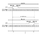
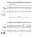
第1実施形態の比較として、往き方向及び戻り方向ともに参照信号φR2をトリガとして、カウンタ回路31をゼロセットした場合について、図3及び図4を用いて説明する。図4は、この比較形態において、測定軸X上の位置と参照信号φR2の立ち上げとの関係を示す図である。往き方向のゼロセットの位置と戻り方向のゼロセットの位置との距離が、カウンタ回路31の12カウント分に相当する。このように往き方向と戻り方向とで参照信号φR2の立ち上げ位置が異なるため、ゼロセットの位置が異なる。したがって、ゼロセット操作は片方の方向に統一しなければならないという制限が生じる。
As a comparison with the first embodiment, a case where the
これに対して、第1実施形態では、往き方向のトリガに参照信号φR2(第2参照信号の一例)、戻り方向のトリガに参照信号φR3(第3参照信号の一例)を用いることにより、往き方向と戻り方向とで、ゼロセットした際の測定軸X上の位置が同じになるようにしている。つまり、戻り方向のゼロセットの位置を補正する処理をしているのである。 On the other hand, in the first embodiment, the reference signal φR2 (an example of the second reference signal) is used for the trigger in the forward direction, and the reference signal φR3 (an example of the third reference signal) is used for the trigger in the return direction. The direction and the return direction are set so that the positions on the measurement axis X when zero setting is the same. That is, the process of correcting the position of the zero set in the return direction is performed.
図5は、第1実施形態において、測定軸X上の位置と参照信号φR2,φR3の立ち上げとの関係を示す図であり、図4と対応する。往き方向では、比較形態と同様に参照信号φR2をトリガにしてゼロセットしている(S1)。一方、戻り方向では、参照信号φR2がアクティブになるよりも遅れてアクティブとなる参照信号φR3をトリガにしてゼロセットしている(S2)。 FIG. 5 is a diagram showing the relationship between the position on the measurement axis X and the rise of the reference signals φR2 and φR3 in the first embodiment, and corresponds to FIG. In the forward direction, as in the comparative example, the reference signal φR2 is used as a trigger to set to zero (S1). On the other hand, in the return direction, the reference signal φR3, which becomes active later than the reference signal φR2 becomes active, is set to zero as a trigger (S2).
参照信号φR3の遅れは、カウンタ回路31の11カウント分に相当する。これは、図4に示すように、参照信号φR2をトリガとした場合における往き方向のゼロセットの位置と戻り方向のゼロセットの位置との間のカウント数(12カウント)を予め求めておき、このカウント数を基にして決定されたものである。これにより、戻り方向のゼロセット(S2)の位置を往き方向のゼロセット(S1)の位置に揃えることができる。なお、アクティブの参照信号φR2をトリガにして、11カウントの計測が開始され、11カウント計測により、参照信号φR3をアクティブにしている。したがって、参照信号φR3は参照信号φR2と同期していることになる。
The delay of the reference signal φR3 corresponds to 11 counts of the
参照信号φR3の遅れ(11カウント分)は、UP/DOWNカウンタでカウントする。このUP/DOWNカウンタは、参照信号φR2がトリガになると共に参照信号φR3の遅れに相当する数をカウントするとアクティブの参照信号φR3を出力する。参照信号φR3の遅れに相当する11カウントの設定は、メーカが変位測定装置の出荷前に行う。この11カウントは、ディップスイッチにより設定してもよいし、マイコンのメモリに記憶させてもよい。また、参照信号φR3のアクティブ期間はUP/DOWNカウンタ等により任意に設定することができる。 The delay (11 counts) of the reference signal φR3 is counted by the UP / DOWN counter. The UP / DOWN counter outputs an active reference signal φR3 when the reference signal φR2 is triggered and the number corresponding to the delay of the reference signal φR3 is counted. The 11-count setting corresponding to the delay of the reference signal φR3 is performed by the manufacturer before shipment of the displacement measuring device. This 11 count may be set by a DIP switch or may be stored in the memory of the microcomputer. The active period of the reference signal φR3 can be arbitrarily set by an UP / DOWN counter or the like.
参照信号φR3の遅れをカウントするUP/DOWNカウンタ37は、図3に示す参照信号φR3の生成回路39(第3参照信号生成回路の一例)に含まれる。カウンタ37には主信号φA2,φB2が加えられ、UP/DOWNカウントを行う。出力端子からは参照信号φR3が出力される。カウンタ37は、参照信号φR2がトリガとなってカウントを開始し、「+11」をカウントすると参照信号φR3をアクティブにする。
The UP /
UP/DOWNカウンタ37を用いることにより、基準位置取りのために、図1のセンサヘッド5を戻り方向に移動させている際に振動等が原因で往き方向に移動しても、その分はDOWNカウントされることになる。これにより、往き方向のゼロセット(S1)の位置の手前で、戻り方向のゼロセット(S2)がされるのを防止できる。つまり、振動等の影響をなくすことができる。
By using the UP /
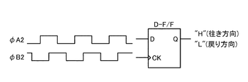
参照信号φR3の生成回路39は、カウント方向弁別回路41を備える。弁別回路41は図6に示すようなDフリップフロップ等のロジック回路やマイコンで構成できる。図6の例では、D入力端子に主信号φA2が加えられ、クロックCK入力端子に主信号φB2が加えられる。
The
図6のように主信号φA2の位相が主信号φB2の位相より90度だけ進んでいる場合、出力端子QからはHレベルの信号が出力される。これはφA2進相であり、通常、図1のセンサヘッド5が往き方向(カウンタ回路31がUPカウント)に移動していることを表す。逆に、主信号φB2の位相が主信号φA2の位相より90度だけ進んでいる場合、出力端子QからはLレベルの信号が出力される(φB2進相)。φB2進相は、通常、センサヘッド5が戻り方向(カウンタ回路31がDOWNカウント)に移動していることを表す。
As shown in FIG. 6, when the phase of the main signal φA2 is advanced by 90 degrees from the phase of the main signal φB2, a signal at H level is output from the output terminal Q. This is a φA binary phase, and normally indicates that the
弁別回路41の出力信号により、スイッチ回路43が制御される。スイッチ回路43は、参照信号φR2が加わる入力端子45、参照信号φR3が加わる入力端子47及びカウンタ回路31のクリアCLR端子(なお、プリセットの場合はプリセット端子)に接続された出力端子49を備える。
The
図1のセンサヘッド5が往き方向に移動している場合、弁別回路41の出力信号により、入力端子45が出力端子49と接続される。これにより、参照信号φR2がカウンタ回路31のクリアCLR端子に入力される。逆に、センサヘッド5が戻り方向に移動している場合、弁別回路41の出力信号により、入力端子47が出力端子49と接続される。したがって、カウンタ回路31のクリアCLR端子には、参照信号φR3が入力される。
When the
往き方向が参照信号φR2、戻り方向が参照信号φR3をトリガにしてゼロセットされたカウンタ回路31でカウントされたパルスを基にして測定値を演算する。この結果がLCD51に表示される。基準位置取りとしてゼロセットの場合で説明したが、プリセットの場合、図5のゼロセットS1,S2において、カウンタ回路にゼロの替わりに、任意の数値がセットされる。
The measured value is calculated based on the pulses counted by the
以上説明したように第1実施形態では、カウンタ回路31のゼロセットのトリガを往き方向及び戻り方向ともに参照信号φR2にするのではなく、往き方向を参照信号φR2とし、戻り方向を参照信号φR3にしている。参照信号φR3は、参照信号φR2がアクティブになるよりも遅れてアクティブとなるので、往き方向と戻り方向でゼロセットの位置を揃えることができる。したがって、基準位置取り操作を片方の方向からに制限する必要がないため、測定の利便性を向上させることができる。
As described above, in the first embodiment, the zero-set trigger of the
なお、図5に示すように、参照信号φR3は、アクティブの参照信号φR2を基にしてアクティブになるため、戻り方向から基準位置取り操作する場合、参照信号φR2がアクティブになる位置より、さらに手前(戻り方向)から基準位置取りの操作を開始しなければならない。 As shown in FIG. 5, the reference signal φR3 becomes active based on the active reference signal φR2, and therefore, when performing the standard positioning operation from the return direction, the reference signal φR2 is further before the position where the reference signal φR2 becomes active. The reference positioning operation must be started from (return direction).
また、ゼロセットのトリガを往き方向について参照信号φR3とし、戻り方向について参照信号φR2にしてもよい。さらに、ゼロセットのトリガを往き方向、戻り方向とも参照信号φR3にすることもできる。これを図7で説明する。図7は、第1実施形態の変形例であり、測定軸X上の位置と参照信号φR2,φR3の立ち上げとの関係を示す図であり、図5と対応する。往き方向はUP/DOWNカウンタが5カウントすると参照信号φR3がアクティブになるようし、戻り方向は6カウントすると参照信号φR3がアクティブになるようしている。この変形例によっても、往き方向と戻り方向でゼロセットの位置を揃えることができる。
[第2実施形態]
第2実施形態では、往き方向、戻り方向ともに、ゼロセットのためのトリガを参照信号φR2にしている。参照信号φR2をトリガにしてカウンタ回路にセットする値(初期値)は、往き方向をゼロとし、戻り方向をゼロから後戻りした値としている。第1実施形態のカウンタ回路にセットされる値はゼロであるが、第2実施形態のカウンタ回路にはゼロ以外の値もセットされる。したがって、第2実施形態では、カウンタ回路にセットされる値を初期値という表現を用いる。以下、第2実施形態について、第1実施形態との相違を中心に説明する。
Also, the zero-set trigger may be the reference signal φR3 for the forward direction and the reference signal φR2 for the return direction. Further, the zero-set trigger can be set to the reference signal φR3 in both the forward direction and the return direction. This will be described with reference to FIG. FIG. 7 is a modification of the first embodiment, and is a diagram showing the relationship between the position on the measurement axis X and the rise of the reference signals φR2 and φR3, and corresponds to FIG. In the forward direction, the reference signal φR3 becomes active when the UP / DOWN counter counts five, and when the return direction counts six, the reference signal φR3 becomes active. Also according to this modification, the zero set position can be aligned in the forward direction and the return direction.
[Second Embodiment]
In the second embodiment, the trigger for zero setting is the reference signal φR2 in both the forward direction and the return direction. A value (initial value) set in the counter circuit with the reference signal φR2 as a trigger is a value obtained by setting the forward direction to zero and the return direction to return from zero. The value set in the counter circuit of the first embodiment is zero, but a value other than zero is also set in the counter circuit of the second embodiment. Therefore, in the second embodiment, the expression “initial value” is used as the value set in the counter circuit. Hereinafter, the second embodiment will be described focusing on differences from the first embodiment.
図8は、第2実施形態において、測定軸X上の位置と参照信号φR2の立ち上げとの関係を示す図であり、図5と対応する。往き方向のトリガ発生と戻り方向のトリガ発生との間のカウント数(12カウント)を予め求めておく。そして、変位測定装置をゼロセットする場合、往き方向についてはカウンタ回路にゼロが初期値としてセットされるように設定し、一方、戻り方向については、カウンタ回路にゼロでなく、ゼロから後戻りした値である「+11」が初期値としてセットされるように設定する(往き方向のトリガ発生と戻り方向のトリガ発生との間の距離に相当する数を差し引く)。これにより、戻り方向から変位を測定する際のゼロセットの位置を補正し、往き方向のゼロセットの位置に揃えることができる。また、戻り方向からのゼロセットでは、往き方向でのゼロセットの位置まで到達しなくても往き方向のゼロセットの位置に揃えることができる(つまり、「+11」が初期値としてセットされた段階でゼロセットが完了し、測定を開始できる。)。よって、基準位置取り操作を片方の方向からに制限する必要がないため、測定の利便性が向上する。 FIG. 8 is a diagram showing the relationship between the position on the measurement axis X and the rise of the reference signal φR2 in the second embodiment, and corresponds to FIG. The number of counts (12 counts) between the generation of the trigger in the forward direction and the generation of the trigger in the return direction is obtained in advance. When the displacement measuring device is set to zero, the counter direction is set so that zero is set as the initial value for the forward direction, while the return direction is not zero in the counter circuit, but a value that is set back from zero. Is set to be set as an initial value (subtract the number corresponding to the distance between the trigger occurrence in the forward direction and the trigger occurrence in the return direction). Thereby, the position of the zero set when measuring the displacement from the return direction can be corrected and aligned with the position of the zero set in the forward direction. Further, in the zero set from the return direction, it is possible to align with the zero set position in the forward direction without reaching the zero set position in the forward direction (that is, the stage where “+11” is set as the initial value) The zero set is completed and the measurement can be started.) Therefore, it is not necessary to limit the reference positioning operation from one direction, and the convenience of measurement is improved.
後戻りした値とは、戻り方向の場合、カウンタ回路がカウントダウンするので、ゼロ(基準値)より大きい値である。逆に、往き方向の場合、カウンタ回路がカウントアップするので、ゼロ(基準値)より小さい値である。 The backward value is a value larger than zero (reference value) because the counter circuit counts down in the return direction. On the other hand, in the forward direction, the counter circuit counts up, so the value is smaller than zero (reference value).
図9は、第2実施形態に係る変位測定装置に備えられる回路部のブロック図であり、図3と対応する。図3のブロック図と相違する点を主に説明する。カウント方向弁別回路41からの出力信号は、初期値選択回路53に入力する。回路41からの出力信号が往き方向を示す場合は基準値(図8の場合はゼロ)を選択し、戻り方向を示す場合は基準値から後戻りした値である後戻値(図8の場合は「+11」)を選択する。
FIG. 9 is a block diagram of a circuit unit provided in the displacement measuring apparatus according to the second embodiment, and corresponds to FIG. Differences from the block diagram of FIG. 3 will be mainly described. An output signal from the count
参照信号φR2の立ち上りがカウンタ回路31のLOAD端子に入力すると、往き方向から基準位置取りしている場合はカウンタ回路31にゼロがセットされ、戻り方向の場合は「+11」がセットされて、計測が開始される。したがって、第2実施形態も往き方向と戻り方向でゼロセットの位置を同じにすることができる。
When the rising edge of the reference signal φR2 is input to the LOAD terminal of the
なお、往き方向、戻り方向ともに、ゼロ(基準値)から後戻りした値を初期値にすることができる。これを変形例として説明する。図10は、第2実施形態の変形例において、測定軸X上の位置と参照信号φR2の立ち上げとの関係を示す図である。 In both the forward direction and the return direction, a value returned from zero (reference value) can be set as the initial value. This will be described as a modification. FIG. 10 is a diagram illustrating the relationship between the position on the measurement axis X and the rise of the reference signal φR2 in the modification of the second embodiment.
往き方向から測定する場合、参照信号φR2をトリガにしてカウンタ回路31に「−5」をセットする。この場合、カウンタ回路31がカウントアップするので、ゼロ(基準値)より小さい値が後戻りした値となる。一方、戻り方向から測定する場合、「+6」をセットする。以上により、往き方向の場合のゼロセットの位置と、戻り方向の場合のそれとを同じにすることができる。
[本発明が適用可能な態様]
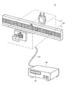
カウンタ回路31は、メインスケール及びセンサヘッドで構成されるアセンブリと分離していてもよいし(分離型)、アセンブリに組み込まれていてもよい(一体型)。図11は、分離型の変位測定装置を示す図であり、図1と対応する。変位測定装置1は、メインスケール3及びセンサヘッド5を部品として組み立てられたアセンブリ55と、ケーブル57によりアセンブリ55に接続可能なカウント・表示装置59(カウント装置の一例)と、を備える。装置59には、図3(第1実施形態)に示すカウンタ回路31及びLCD51が組み込まれるようにしてもよいし、また、図9(第2実施形態)に示すカウンタ回路31、カウント方向弁別回路41、初期値選択回路53及びLCD51が組み込まれるようにしてもよい。
When measuring from the forward direction, “−5” is set in the
[Aspects to which the present invention is applicable]
The
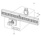
一方、図12は、一体型の変位測定装置を示す図であり、図1と対応する。センサヘッド5に、図3や図9に示すカウンタ回路31及びLCD51が組み込まれている。
On the other hand, FIG. 12 is a view showing an integrated displacement measuring device, which corresponds to FIG. The
また、図1に示すように、インデックススケール11を含むセンサヘッド5がメインスケール3の上を移動する場合で説明した。この逆、つまり、メインスケール3がセンサヘッド5の上を移動する態様でもよい。よって、本発明では、インデックススケールはメインスケールに対して相対移動可能と言うことができる。
Further, as shown in FIG. 1, the case where the
また、光源17からの光Lはメインスケール3を透過して、インデックススケール11に照射されるタイプ(透過型)で説明した。しかしながら、本発明は、光源からの光をメインスケールで反射させて、インデックススケールに照射するタイプ(反射型)にも適用することができる。
Further, the light L from the
1・・・インクリメンタル型変位測定装置、3・・・メインスケール、5・・・センサヘッド、7・・・光学格子(主信号用光学格子の一例)、9・・・光学格子(参照信号用光学格子の一例)、11・・・インデックススケール、13,13a,13b,13aa,13bb・・・光学格子(主信号用光学格子の一例)、15・・・光学格子(参照信号用光学格子の一例)、17・・・光源、19・・・受光部、21a,21b,21aa,21bb,23・・・フォトダイオード、25・・・合成回路、27・・・アンプ回路、29・・・内挿回路、31・・・カウンタ回路、33・・・参照信号φR1生成回路(第1参照信号生成回路の一例)、35・・・参照信号φR2生成回路(第2参照信号生成回路の一例)、37・・・UP/DOWNカウンタ、39・・・参照信号φR3生成回路(第3参照信号生成回路の一例)、41・・・カウント方向弁別回路、43・・・スイッチ回路、45,47・・・入力端子、49・・・出力端子、51・・・LCD、53・・・初期値選択回路、55・・・アセンブリ、57・・・ケーブル、59・・・カウント・表示装置、X・・・測定軸、L・・・光、φa,φb,φaa,φbb・・・主信号(合成処理前)、φr・・・参照信号(二値化処理前)、φA1,φB1・・・主信号(合成処理後)、φR1・・・参照信号(第1参照信号の一例)、φR2・・・参照信号(第2参照信号の一例)、φA2,φB2・・・パルス(インクリメンタル測定のカウント用のパルスの一例)、D・・・参照信号φR2の往き方向の立ち上りエッジと戻り方向の立ち上りエッジとの距離、φR3・・・参照信号(第3参照信号の一例)、S1・・・参照信号φR2をトリガにしたゼロセット、S2・・・参照信号φR3をトリガにしたゼロセット
DESCRIPTION OF
Claims (7)
一方の方向及びこれと逆の他方の方向に測定軸に沿って前記メインスケールに対して相対移動可能であると共に前記メインスケールと対向して配置されたインデックススケールと、
前記メインスケール及び前記インデックススケールに設けられると共にインクリメンタル測定のカウント用のパルスの基になる主信号を生成するための主信号用光学格子と、
前記メインスケール及び前記インデックススケールに設けられると共に前記インクリメンタル測定における基準位置の特定用の参照信号を生成するための参照信号用光学格子と、
前記メインスケールに対する前記インデックススケールの相対移動により、前記参照信号用光学格子を基にして主信号と非同期の参照信号である第1参照信号を生成する第1参照信号生成回路と、
前記一方の方向と前記他方の方向とでアクティブとなる位置が異なる参照信号である第2参照信号を第1参照信号のアクティブ中に主信号と同期するように生成する第2参照信号生成回路と、
第2参照信号と同期すると共に第2参照信号がアクティブになるよりも遅れてアクティブとなる参照信号である第3参照信号を生成する第3参照信号生成回路と、
主信号を基に生成された前記インクリメンタル測定のカウント用のパルスの数をカウントすると共に前記インクリメンタル測定の基準位置を示す基準値のセットのトリガが前記一方の方向から変位を測定する場合は第2又は第3参照信号であり、前記他方の方向から変位を測定する場合は第3参照信号であるカウンタ回路と、を備える
ことを特徴とするインクリメンタル型変位測定装置。 The main scale,
An index scale that is movable relative to the main scale along the measurement axis in one direction and the other direction opposite thereto, and disposed opposite the main scale;
An optical grating for a main signal provided on the main scale and the index scale and for generating a main signal that is a basis of a pulse for counting an incremental measurement;
A reference signal optical grating provided on the main scale and the index scale and for generating a reference signal for specifying a reference position in the incremental measurement;
A first reference signal generation circuit that generates a first reference signal that is an asynchronous reference signal to the main signal based on the reference signal optical grating by relative movement of the index scale with respect to the main scale;
A second reference signal generation circuit configured to generate a second reference signal, which is a reference signal having different active positions in the one direction and the other direction, in synchronization with the main signal while the first reference signal is active; ,
A third reference signal generation circuit that generates a third reference signal that is a reference signal that becomes active later than the second reference signal becomes active while being synchronized with the second reference signal;
When the number of pulses for counting the incremental measurement generated based on the main signal is counted and the trigger of the reference value set indicating the reference position of the incremental measurement measures the displacement from the one direction, the second is used. Or a counter circuit that is a third reference signal and that is a third reference signal when displacement is measured from the other direction. An incremental displacement measuring apparatus.
第2参照信号をトリガとした場合における前記一方の方向の前記基準値セットの位置と前記他方の方向の前記基準値セットの位置との間のカウント数を予め求めておき、このカウント数を基にして第3参照信号の遅れを設定する、
ことを特徴とする請求項1に記載のインクリメンタル型変位測定装置。 When measuring displacement from the one direction, the second reference signal triggers the set of reference values,
When the second reference signal is used as a trigger, a count number between the position of the reference value set in the one direction and the position of the reference value set in the other direction is obtained in advance, and this count number is used as a basis. To set the delay of the third reference signal,
The incremental displacement measuring apparatus according to claim 1.
ことを特徴とする請求項2に記載のインクリメンタル型変位測定装置。 An UP / DOWN counter that outputs an active third reference signal when the second reference signal is triggered and the number corresponding to the delay of the third reference signal is counted;
The incremental displacement measuring device according to claim 2.
一方の方向及びこれと逆の他方の方向に測定軸に沿って前記メインスケールに対して相対移動可能であると共に前記メインスケールと対向して配置されたインデックススケールと、
前記メインスケール及び前記インデックススケールに設けられると共にインクリメンタル測定のカウント用のパルスの基になる主信号を生成するための主信号用光学格子と、
前記メインスケール及び前記インデックススケールに設けられると共に前記インクリメンタル測定における基準位置の特定用の参照信号を生成するための参照信号用光学格子と、
前記メインスケールに対する前記インデックススケールの相対移動により、前記参照信号用光学格子を基にして主信号と非同期の参照信号である第1参照信号を生成する第1参照信号生成回路と、
前記一方の方向と前記他方の方向とでアクティブとなる位置が異なる参照信号である第2参照信号を第1参照信号のアクティブ中に主信号と同期するように生成する第2参照信号生成回路と、
主信号を基に生成された前記インクリメンタル測定のカウント用のパルスの数をカウントすると共に第2参照信号をトリガにして初期値がセットされるカウンタ回路と、を備え、
前記一方の方向から変位を測定する場合の前記初期値は、前記インクリメンタル測定の基準位置を示す基準値又は前記基準値から後戻りした値であり、
前記他方の方向から変位を測定する場合の前記初期値は、前記基準値から後戻りした値である、
ことを特徴とするインクリメンタル型変位測定装置。 The main scale,
An index scale that is movable relative to the main scale along the measurement axis in one direction and the other direction opposite thereto, and disposed opposite the main scale;
An optical grating for a main signal provided on the main scale and the index scale and for generating a main signal that is a basis of a pulse for counting an incremental measurement;
A reference signal optical grating provided on the main scale and the index scale and for generating a reference signal for specifying a reference position in the incremental measurement;
A first reference signal generation circuit that generates a first reference signal that is an asynchronous reference signal to the main signal based on the reference signal optical grating by relative movement of the index scale with respect to the main scale;
A second reference signal generation circuit configured to generate a second reference signal, which is a reference signal having different active positions in the one direction and the other direction, in synchronization with the main signal while the first reference signal is active; ,
A counter circuit that counts the number of pulses for counting the incremental measurement generated based on a main signal and that is set with an initial value triggered by a second reference signal;
The initial value in the case of measuring displacement from the one direction is a reference value indicating a reference position of the incremental measurement or a value backward from the reference value,
When the displacement is measured from the other direction, the initial value is a value that is reversed from the reference value.
Incremental displacement measuring apparatus characterized by the above.
前記他方の方向から変位を測定する場合の前記初期値である前記後戻りした値は、前記一方の方向のトリガ発生と前記他方の方向のトリガ発生との間の予め求められていたカウント数を基にして設定される、
ことを特徴とする請求項4に記載のインクリメンタル型変位測定装置。 The initial value when measuring displacement from the one direction is the reference value;
The backward value, which is the initial value when measuring the displacement from the other direction, is based on a count number obtained in advance between the trigger occurrence in the one direction and the trigger occurrence in the other direction. Set as
The incremental displacement measuring device according to claim 4.
前記カウンタ回路が組み込まれると共に前記アセンブリとケーブルにより接続可能なカウント装置と、を備える
ことを特徴とする請求項1〜5のいずれか一項に記載のインクリメンタル型変位測定装置。 An assembly assembled with the main scale and the index scale as parts;
The incremental displacement measuring device according to any one of claims 1 to 5, further comprising a counting device in which the counter circuit is incorporated and connected to the assembly by a cable.
ことを特徴とする請求項1〜5のいずれか一項に記載のインクリメンタル型変位測定装置。 The counter circuit is incorporated in an assembly in which the main scale and the index scale are assembled as parts.
An incremental displacement measuring apparatus according to any one of claims 1 to 5, wherein
Priority Applications (1)
| Application Number | Priority Date | Filing Date | Title |
|---|---|---|---|
| JP2004111070A JP2005292078A (en) | 2004-04-05 | 2004-04-05 | Incremental type displacement measuring instrument |
Applications Claiming Priority (1)
| Application Number | Priority Date | Filing Date | Title |
|---|---|---|---|
| JP2004111070A JP2005292078A (en) | 2004-04-05 | 2004-04-05 | Incremental type displacement measuring instrument |
Publications (1)
| Publication Number | Publication Date |
|---|---|
| JP2005292078A true JP2005292078A (en) | 2005-10-20 |
Family
ID=35325154
Family Applications (1)
| Application Number | Title | Priority Date | Filing Date |
|---|---|---|---|
| JP2004111070A Pending JP2005292078A (en) | 2004-04-05 | 2004-04-05 | Incremental type displacement measuring instrument |
Country Status (1)
| Country | Link |
|---|---|
| JP (1) | JP2005292078A (en) |
Cited By (1)
| Publication number | Priority date | Publication date | Assignee | Title |
|---|---|---|---|---|
| JP2014182015A (en) * | 2013-03-19 | 2014-09-29 | Dmg Mori Seiki Co Ltd | Measuring machine and origin position detection method |
-
2004
- 2004-04-05 JP JP2004111070A patent/JP2005292078A/en active Pending
Cited By (1)
| Publication number | Priority date | Publication date | Assignee | Title |
|---|---|---|---|---|
| JP2014182015A (en) * | 2013-03-19 | 2014-09-29 | Dmg Mori Seiki Co Ltd | Measuring machine and origin position detection method |
Similar Documents
| Publication | Publication Date | Title |
|---|---|---|
| JP5379761B2 (en) | Absolute encoder | |
| EP2343510B1 (en) | Rotary encoder | |
| TWI485368B (en) | Photosensor for position detecting device, position detecting device using same and position detecting method | |
| JPS6331722B2 (en) | ||
| JP6308739B2 (en) | POSITION DETECTION DEVICE, LENS DEVICE HAVING THE SAME, IMAGE READING DEVICE, AND IMAGE FORMING DEVICE | |
| JPH0122883B2 (en) | ||
| KR20140117500A (en) | Method and apparatus for determining position | |
| JP4875889B2 (en) | Encoder count error detection circuit and encoder count error detection method | |
| JP6359938B2 (en) | Interpolation method of incremental encoder read signal | |
| JP4274751B2 (en) | Encoder | |
| CN102168996A (en) | Photoelectric encoder | |
| EP2241855B1 (en) | Optical measuring apparatus and method | |
| JP2005337843A (en) | Optical encoder | |
| US6285023B1 (en) | Apparatus for generating origin signal of optical linear scale | |
| JP2005292078A (en) | Incremental type displacement measuring instrument | |
| JP5747342B2 (en) | Optical encoder | |
| JP5550213B2 (en) | Optical absolute encoder | |
| JP2009047595A (en) | Absolute position length-measurement type encoder | |
| JP6087722B2 (en) | Origin signal generator and origin signal generation system | |
| JP2015087193A (en) | Position detection device and lens device including the same and imaging device | |
| JP6570994B2 (en) | Origin determination method of optical encoder and system using optical encoder | |
| JP2014224745A (en) | Origin signal generating device and origin signal generating system | |
| JPH0143243B2 (en) | ||
| EP2738523A2 (en) | Absolute encoder and method of obtaining absolute position | |
| JP2001041730A (en) | Linear scale |