JP2005292044A - Electromagnetic ultrasonic measuring device - Google Patents
Electromagnetic ultrasonic measuring device Download PDFInfo
- Publication number
- JP2005292044A JP2005292044A JP2004110266A JP2004110266A JP2005292044A JP 2005292044 A JP2005292044 A JP 2005292044A JP 2004110266 A JP2004110266 A JP 2004110266A JP 2004110266 A JP2004110266 A JP 2004110266A JP 2005292044 A JP2005292044 A JP 2005292044A
- Authority
- JP
- Japan
- Prior art keywords
- electromagnetic ultrasonic
- inspection object
- sensor unit
- sensor
- ultrasonic waves
- Prior art date
- Legal status (The legal status is an assumption and is not a legal conclusion. Google has not performed a legal analysis and makes no representation as to the accuracy of the status listed.)
- Granted
Links
Images


Landscapes
- Length Measuring Devices Characterised By Use Of Acoustic Means (AREA)
- Investigating Or Analyzing Materials By The Use Of Ultrasonic Waves (AREA)
Abstract
【課題】 専用の治具を必要とすることなく配管の肉厚や欠陥の測定を簡便に連続測定できる電磁超音波計測装置を提供することである。
【解決手段】 計測装置本体11は、検査対象物に対して電磁超音波を送受信する1または複数のセンサ部14及び演算制御装置18を収納し、自ら検査対象物に沿って移動する。計測装置本体11の移動中に、演算制御装置18は、予め定められた時間間隔で、センサ部14での電磁超音波の送受信タイミングを制御するとともに、センサ部14で受信した電磁超音波に含まれる検査対象物の厚さまたは欠陥の情報を記憶する。
【選択図】 図1PROBLEM TO BE SOLVED: To provide an electromagnetic ultrasonic measuring apparatus capable of easily and continuously measuring the thickness of a pipe and a defect without requiring a dedicated jig.
A measuring device main body 11 houses one or a plurality of sensor units 14 and a calculation control device 18 that transmit and receive electromagnetic ultrasonic waves to and from an inspection object, and moves along the inspection object itself. While the measuring device main body 11 is moving, the arithmetic and control unit 18 controls the transmission / reception timing of the electromagnetic ultrasonic waves at the sensor unit 14 at predetermined time intervals and is included in the electromagnetic ultrasonic waves received by the sensor unit 14. Information on the thickness or defect of the inspection object to be checked is stored.
[Selection] Figure 1
Description
本発明は、電磁超音波を検査対象物に送信してその反射波を受信し検査対象物の肉厚や欠陥を測定する電磁超音波計測装置に関する。 The present invention relates to an electromagnetic ultrasonic measurement apparatus that transmits electromagnetic ultrasonic waves to an inspection object, receives a reflected wave thereof, and measures a thickness or a defect of the inspection object.
一般に、超音波探触子は圧電素子に電圧を印加して振動を発生させ、その振動を検査対象物に送信し、反射波を受信して肉厚や欠陥を測定するものである。この場合、音波インピーダンスが高い空気の伝搬を避けるために、超音波探触子と検査対象物との間に接触媒質を設けている。 In general, an ultrasonic probe generates a vibration by applying a voltage to a piezoelectric element, transmits the vibration to an inspection object, receives a reflected wave, and measures a thickness and a defect. In this case, a contact medium is provided between the ultrasonic probe and the inspection object in order to avoid the propagation of air having high acoustic impedance.
例えば、発電プラントにおける各種配管の肉厚を超音波探触子により測定する場合には、配管の外部表面に接触媒質を介して超音波探触子を配置し、超音波探触子から超音波を送信し反射エコーを受信することにより配管の肉厚を測定している。この場合、超音波探触子を移動させるたびに接触媒質を配置しなければならないので、通常、配管の肉厚測定は配管の一部分における定点計測で行われている。最近は、配管の全域に亘って減肉状態を把握するできるようにするため、配管の一部分だけでなく配管の全域における肉厚を連続測定することが要請されている。 For example, when measuring the wall thickness of various pipes in a power plant with an ultrasonic probe, an ultrasonic probe is placed on the external surface of the pipe via a contact medium, and the ultrasonic probe The wall thickness of the pipe is measured by transmitting the signal and receiving the reflected echo. In this case, since the contact medium must be arranged each time the ultrasonic probe is moved, the thickness measurement of the pipe is usually performed by fixed point measurement in a part of the pipe. Recently, in order to be able to grasp the thinning state over the entire area of the piping, it is required to continuously measure the wall thickness not only in a part of the piping but also in the entire area of the piping.
一方、非接触で超音波を受発信できる電磁超音波計測装置がある。この電磁超音波計測装置は、圧電素子に代えて電磁的に超音波の送受信を行うものであり、接触媒質が不要であり、塗装除去作業や錆落とし作業が不要などの利点があるため、主として鉄鋼業の上位熱間工程での肉質検査、厚み計測、各種配管類、ガス管、通信用ケーブル管路の減肉状態の調査への応用などを目指して技術開発されている(例えば、非特許文献1参照)。
しかし、配管などの肉厚測定を連続測定で行う際には、配管の外に足場を組み専用の治具を設置するなどして大がかりな事前準備をした後に、配管に沿って肉厚を測定していくことになるので、配管の肉厚測定のための事前準備に時間やコストがかかることになる。また、配管肉厚の測定作業においても、測定装置を配管に沿って移動させていかなければならないので作業量が多くなる。特に、配管は直管部だけでなく曲管部も有しており、さらに、超音波探触子を用いて行う場合には接触媒質が必要となるので作業量はさらに増大する。 However, when measuring the thickness of pipes, etc., by continuous measurement, measure the thickness along the pipes after extensive preparations such as mounting a scaffold outside the pipes and installing a dedicated jig. Therefore, it takes time and cost to prepare in advance for pipe thickness measurement. Also, in the pipe wall thickness measurement work, the measuring device must be moved along the pipe, which increases the amount of work. In particular, the piping has not only a straight pipe part but also a curved pipe part. Further, when the ultrasonic probe is used, a contact medium is required, and the work amount is further increased.
本発明に目的は、専用の治具を必要とすることなく配管の肉厚や欠陥の測定を簡便に連続測定できる電磁超音波計測装置を提供することである。 An object of the present invention is to provide an electromagnetic ultrasonic measurement apparatus that can easily and continuously measure the thickness and defects of pipes without requiring a dedicated jig.
請求項1の発明に係わる電磁超音波計測装置は、検査対象物に対して電磁超音波を送信するとともに電磁超音波を受信する1または複数のセンサ部と、予め定められた時間間隔で前記センサ部での電磁超音波の送受信タイミングを制御するとともに受信した電磁超音波に含まれる検査対象物の厚さまたは欠陥の情報を記憶する演算制御装置と、前記センサ部及び前記演算制御装置を収納し自ら検査対象物に沿って移動可能に形成された計測装置本体とを備えたことを特徴とする。 The electromagnetic ultrasonic measurement apparatus according to the first aspect of the present invention includes one or a plurality of sensor units that transmit electromagnetic ultrasonic waves to an object to be inspected and receive electromagnetic ultrasonic waves, and the sensors at predetermined time intervals. An arithmetic and control unit for controlling transmission / reception timing of the electromagnetic ultrasonic wave at the unit and storing information on the thickness or defect of the inspection object included in the received electromagnetic ultrasonic wave, and the sensor unit and the arithmetic and control unit And a measuring device main body formed so as to be movable along the inspection object itself.
請求項2の発明に係わる電磁超音波計測装置は、検査対象物に対して電磁超音波を送信するとともに電磁超音波を受信する1または複数のセンサ部と、1または複数のセンサ部と検査対象物との間の距離を測定する距離センサと、前記距離センサで測定されたセンサ部と検査対象物との間の距離に基づいて前記センサ部での電磁超音波の送受信タイミングを制御するとともに受信した電磁超音波に含まれる検査対象物の厚さまたは欠陥の情報を記憶する演算制御装置と、前記センサ部及び前記演算制御装置を収納し自ら検査対象物に沿って移動可能に形成された計測装置本体とを備えたことを特徴とする。 An electromagnetic ultrasonic measurement apparatus according to a second aspect of the invention includes one or more sensor units that transmit electromagnetic ultrasonic waves to an inspection object and receive electromagnetic ultrasonic waves, one or more sensor units, and an inspection object. A distance sensor that measures the distance between the object and the transmission / reception timing of the electromagnetic ultrasonic wave at the sensor unit based on the distance between the sensor unit measured by the distance sensor and the inspection object, and reception A calculation control device that stores information on the thickness or defect of the inspection object included in the electromagnetic ultrasonic wave, and a measurement that is formed so as to be movable along the inspection object by housing the sensor unit and the calculation control device. An apparatus main body is provided.
請求項3の発明に係わる電磁超音波計測装置は、請求項2の発明において、前記演算制御装置は、各々の距離センサで検出された前記検査対象物までの距離が最短のセンサ部を判定し、その最短のセンサ部に対して電磁超音波を送信するとともに電磁超音波を受信し、受信した電磁超音波に含まれる検査対象物の厚さまたは欠陥を記憶することを特徴とする。 According to a third aspect of the present invention, there is provided the electromagnetic ultrasonic measurement apparatus according to the second aspect, wherein the arithmetic and control unit determines the sensor unit having the shortest distance to the inspection object detected by each distance sensor. The electromagnetic ultrasonic wave is transmitted to the shortest sensor unit, the electromagnetic ultrasonic wave is received, and the thickness or defect of the inspection object included in the received electromagnetic ultrasonic wave is stored.
請求項4の発明に係わる電磁超音波計測装置は、請求項1ないし請求項3のいずれか一の発明において、前記計測装置本体は、自ら検査対象物に沿って転がる形状に形成されたことを特徴とする。 According to a fourth aspect of the present invention, there is provided the electromagnetic ultrasonic measurement apparatus according to any one of the first to third aspects, wherein the measurement apparatus main body is formed in a shape that rolls along the object to be inspected. Features.
本発明によれば、計測装置本体は自ら検査対象物に沿って移動可能に形成されているので、検査対象物である配管内部の上部に電磁超音波計測装置を投げ入れるだけで、重力により配管の上部から配管の下部に移動する。従って、電源を入れて検査対象物である配管内部に電磁超音波計測装置を投げ入れると、センサ部から電磁超音波を送信するとともに電磁超音波を受信しながら、検査対象物である配管内部を移動するので、連続的に配管の長さ方向の肉厚や欠陥を測定できる。また、電磁超音波の特性上、接触媒質や検査面の手入れなどが不要であるので、専用治具の事前準備が不要であり、コストを削減できるとともに検査作業効率が向上する。水平管においては、必要な初速度を与えて電磁超音波計測装置を配管のある地点より投げ入れた後、他のある地点で回収することで、検査対象物である配管の長さ方向の肉厚や欠陥を連続的に測定できる。 According to the present invention, the measuring device main body is formed so as to be movable along the inspection object itself. Move from the top to the bottom of the pipe. Therefore, when the electromagnetic ultrasonic measurement device is thrown into the inspection target pipe after the power is turned on, the electromagnetic wave is transmitted from the sensor unit and the electromagnetic ultrasonic wave is received, and the inside of the inspection target pipe is moved. Therefore, the thickness and defects in the length direction of the pipe can be measured continuously. In addition, because of the characteristics of electromagnetic ultrasonic waves, it is not necessary to care for the contact medium or the inspection surface, so that it is not necessary to prepare a dedicated jig in advance, thereby reducing costs and improving inspection work efficiency. For horizontal pipes, throw the electromagnetic ultrasonic measurement device from a certain point on the pipe after giving the required initial velocity, and then collect it at another point, so that the thickness in the length direction of the pipe that is the inspection object And can continuously measure defects.
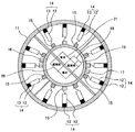
以下、本発明の実施の形態を説明する。図1は本発明の第1の実施の形態に係わる電磁超音波計測装置の構成を示す断面図である。計測装置本体11は球体に形成され、自ら検査対象物に沿って移動可能な形状に形成されている。計測装置本体11の内部には、磁石12とコイル13とからなる複数個のセンサ部14が設けられている。図1では、断面図であることから平面的に12個のセンサ部14が配置されているものを図示しているが、計測装置本体11は球体に形成されるので、複数個のセンサ部14は球体内面に立体的に配置される。なお、磁石12は永久磁石であってもよいし電磁石であってもよい。
Embodiments of the present invention will be described below. FIG. 1 is a cross-sectional view showing the configuration of the electromagnetic ultrasonic measurement apparatus according to the first embodiment of the present invention. The measuring device
また、各々のセンサ部14には切替器15が設けられ、この切替器15はセンサ部14の接続をパルサー16またはレシーバー17のいずれかに切り替えるものであり、その切り替えは演算制御装置18により制御される。センサ部14は、切替器15の切り替えにより、パルサー16から検査対象物に対して電磁超音波を送信し、レシーバー17により電磁超音波を受信する。
Each
演算制御装置18は、設定器19に予め定められた時間間隔に基づいて、各々のセンサ部14での電磁超音波の送受信タイミングを制御するとともに、受信した電磁超音波に含まれる検査対象物の厚さまたは欠陥の情報を記憶する。電源部20には電池21から電源が供給され、電源部20から、センサ部14、切替器15、パルサー16、レシーバー17及び演算制御装置18等に必要な電源が供給される。磁石12が電磁石である場合には電源部20からの電源で励磁されることになる。
The arithmetic and
センサ部14の磁石12は検査対象物に対して磁界を与えるものであり、肉厚や欠陥の測定時には検査対象物に磁石12により磁界が与えられている。この状態で、演算制御装置18は切替器15によりコイル13をパルサー16に接続する。これにより、パルサー16はコイル13にパルス電流を印加する。そして、演算制御装置18は、パルサー16がコイル13にパルス電流を印加した後に、切替器15によりコイル13をレシーバー17に接続する。
The
コイル13にパルス電流が印加されると検査対象物の表面に渦電流が誘起され、磁石12により与えられている磁界とこの渦電流によりローレンツ力が検査対象物に働き、機械的変位が生じて超音波が発生する。この超音波は検査対象物中を伝搬し、裏面あるいは欠陥で反射し、再び検査対象物の表面に戻ってくる。超音波が検査対象物の表面に戻ってくると、磁石12により与えられた磁界中で検査対象物が機械的変位をすることになるので、ファラディーの電磁誘導の法則により起電力が発生し再び渦電流が発生する。この渦電流による磁界変化はコイル13に起電力を発生する。この起電力をレシーバー17で受信し、演算制御装置18に入力する。
When a pulse current is applied to the
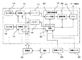
図2は本発明の第1の実施の形態に係わる電磁超音波計測装置のブロック構成図である。電源部20には電池21から電源が供給され、電源部20から、センサ部14、切替器15、パルサー16、レシーバー17及び演算制御装置18にそれぞれ必要な電源が供給される。設定器19には、各々のセンサ部14での電磁超音波の送受信タイミングを定めるための時間間隔が予め設定されている。例えば、時間間隔としてΔt1が設定された場合には、各々のセンサ部14は順次時間間隔Δt1で超音波の送受信を行う。
FIG. 2 is a block diagram of the electromagnetic ultrasonic measurement apparatus according to the first embodiment of the present invention. Power is supplied from the
演算制御装置18のコントロール回路22は、設定器19に設定された時間間隔Δt1で、順次各々のセンサ部14の切替器15に対してパルサー16からパルス電流を印加して、そのパルス電流の印加後にレシーバー17に切り替える。そして、ゲート回路23を開き、レシーバー17から受信した反射波を演算回路24に入力する。演算回路24は受信した電磁超音波の反射波に含まれる検査対象物の厚さまたは欠陥をメモリ25に記憶する。
The
いま、電源部20をオンにして、検査対象物である配管内部の上部に電磁超音波計測装置を投げ入れたとする。計測装置本体11は球体で形成されているので、電磁超音波計測装置は、投げ入れた初速度で重力によりさらに加速されて配管の上部から配管の下部に移動する。
Now, it is assumed that the
この電磁超音波計測装置の移動中において、センサ部14から電磁超音波を送信するとともに電磁超音波を受信する。この電磁超音波の送受信は電磁超音波計測装置の移動速度に比較して極めて早いので、センサ部14は、事実上、電磁超音波を送信した位置でその反射波を受信することになる。この受信した超音波の反射波を演算回路24により順次メモリ25に記憶する。そして、検査対象物である配管内部の下部で電磁超音波計測装置を回収し、メモリ25に記憶されたデータを読み出す。このメモリ25に記憶されたデータを解析することにより、検査対象物である配管の肉厚や欠陥を評価できる。
During the movement of the electromagnetic ultrasonic measurement device, the electromagnetic ultrasonic wave is transmitted from the
なお、センサ部14が配管の内面に対面している位置にあるときに、送受信した電磁超音波が配管の肉厚や欠陥の測定に寄与する電磁超音波となる。一方、配管の長手方向に向いているセンサ部14からの電磁超音波の送受信は配管の肉厚や欠陥の測定に寄与しないが、複数個のセンサ部14は球体内面に立体的に配置されているので、電磁超音波計測装置がどの方向に向いても必ず配管の内面に対面しているセンサ部14が存在することになる。従って、電磁超音波計測装置の移動に伴って配管内部の肉厚や欠陥を連続的に計測できる。
When the
以上の説明では、計測装置本体11の形状として球体である場合について説明したが、自ら検査対象物に沿って移動可能な形状であれば何でもよい。例えば、樽形形状や円筒形形状であってもよい。また、自ら移動可能な形状に代えて、計測装置本体11に自ら検査対象物に沿って移動可能となる部材を装着してもよい。例えば、計測装置本体11に車輪やころを装着するようにしてもよい。
In the above description, although the case where the shape of the measurement apparatus
また、複数個のセンサ部14を設けた場合について説明したが、1個のセンサ部14を設けるようにしてもよい。1個のセンサ部14の場合には、そのセンサ部14が配管の長手方向に向いているタイミングで送受信を行った電磁超音波は配管の肉厚や欠陥の測定に寄与しないが、センサ部14が配管の内面に対面している位置にあるときのタイミングで送受信を行った電磁超音波は配管の肉厚や欠陥の測定に寄与するので、メモリ25に記憶されたデータの解析により、配管の肉厚や欠陥の測定に寄与するデータを識別して配管の肉厚や欠陥を判定することになる。
Moreover, although the case where the some
第1の実施の形態によれば、電源を入れて検査対象物である配管内部に電磁超音波計測装置を投げ入れると、電磁超音波計測装置は自走しながら、センサ部から電磁超音波を送信するとともに電磁超音波を受信するので、連続的に配管の長さ方向の肉厚や欠陥を測定できる。 According to the first embodiment, when the electromagnetic ultrasonic measurement device is thrown into the pipe that is the inspection object after the power is turned on, the electromagnetic ultrasonic measurement device transmits the electromagnetic ultrasonic waves from the sensor unit while running on its own. In addition, since the electromagnetic ultrasonic waves are received, the thickness and defects in the length direction of the pipe can be measured continuously.
また、電磁超音波計測装置が配管の内面に接触しなくても、電磁超音波は配管内面に向けて伝搬し、さらに配管内部へ伝搬するので、電磁超音波計測装置の移動に伴って配管内部の肉厚や欠陥を連続的に計測できる。さらに、配管が曲管である場合であっても電磁超音波計測装置が移動できる限りは曲管部の肉厚や欠陥を測定できる。 Even if the electromagnetic ultrasonic measurement device does not contact the inner surface of the pipe, the electromagnetic ultrasonic wave propagates toward the inner surface of the pipe and further propagates into the pipe. Thickness and defects can be measured continuously. Furthermore, even if the pipe is a curved pipe, as long as the electromagnetic ultrasonic measurement device can move, the thickness and defects of the curved pipe portion can be measured.
次に、本発明の第2の実施の形態を説明する。図3は本発明の第2の実施の形態に係わる電磁超音波計測装置の構成を示す断面図である。この第2の実施の形態は、図1に示した第1の実施の形態に対し、設定器19に代えて、センサ部14と検査対象物との間の距離を測定する距離センサ26を設け、演算制御装置18は、距離センサ26で測定されたセンサ部14と検査対象物との間の距離に基づいて、センサ部14での電磁超音波の送受信タイミングを制御するとともに、受信した電磁超音波に含まれる検査対象物の厚さまたは欠陥を記憶するようにしたものである。図1と同一要素には同一符号を付し重複する説明は省略する。
Next, a second embodiment of the present invention will be described. FIG. 3 is a cross-sectional view showing the configuration of an electromagnetic ultrasonic measurement apparatus according to the second embodiment of the present invention. In the second embodiment, a
センサ部14の近傍には、センサ部14と検査対象物との間の距離を測定する距離センサ26が設けられている。距離センサ26は、例えば、光学系のセンサを採用することで検査対象物までの距離を測定する。
A
図4は本発明の第2の実施の形態に係わる電磁超音波計測装置のブロック構成図である。図2に示した第1の実施の形態に対し、演算制御装置18のコントロール回路22は、各々の距離センサ26で測定されたセンサ部14と検査対象物との間の距離を入力し、検査対象物までの距離が最短のセンサ部14に対して電磁超音波を送信するとともに電磁超音波を受信する。
FIG. 4 is a block diagram of an electromagnetic ultrasonic measurement apparatus according to the second embodiment of the present invention. In contrast to the first embodiment shown in FIG. 2, the
すなわち、演算制御装置18のコントロール回路22は、各々の距離センサ26で測定されたセンサ部14と検査対象物との間の距離のうち最短のセンサ部14を判定し、そのセンサ部14の切替器15に対してパルサー16からパルス電流を印加して、そのパルス電流の印加後にレシーバー17に切り替える。そして、ゲート回路23を開き、レシーバー17から受信した反射波を演算回路24に入力し、演算回路24がその反射波をメモリ25に記憶した時点で、コントロール回路22は、再度、検査対象物との距離が最短のセンサ部14を判定する。そして、順次、検査対象物との間の距離が最短のセンサ部14に対して、電磁超音波の送受信を行う。
That is, the
以上の説明では、複数個のセンサ部14を設けた場合について説明したが、1個のセンサ部14を設けるようにしてもよい。なお、1個のセンサ部14の場合には、コントロール回路22は、その1個のセンサ部14の位置が、検査対象物である配管の肉厚や欠陥の測定に寄与できる測定位置にあるか否かを判定することになる。そして、その1個のセンサ14が電磁超音波の送受信を行った場合に、検査対象物である配管の肉厚や欠陥の測定に寄与する範囲内に位置するときは、コントロール回路22は、その1個のセンサ部14に対して電磁超音波の送受信を行うことになる。
In the above description, the case where a plurality of
第2の実施の形態によれば、距離センサ26を設けて、検査対象物までの距離が最短であるセンサ部14を動作させて電磁超音波の送受信を行うので、センサ部14が配管の内面に対面している位置にあるときのタイミングで電磁超音波の送受信を行うことができる。従って、配管の肉厚や欠陥の測定に寄与する電磁超音波のみをメモリ25に記憶することができるので、配管の肉厚や欠陥の解析がし易くなる。
According to the second embodiment, since the
また、1個のセンサ部14の場合であっても、検査対象物である配管の肉厚や欠陥の測定に寄与する範囲内に位置するときに電磁超音波の送受信を行うので、配管の肉厚や欠陥の測定に寄与する電磁超音波のみをメモリ25に記憶することができる。従って、配管の肉厚や欠陥の解析がし易くなる。
Further, even in the case of one
11…計測装置本体、12…磁石、13…コイル、14…センサ部、15…切替器、16…パルサー、17…レシーバー、18…演算制御装置、19…設定器、20…電源部、21…電池、22…コントロール回路、23…ゲート回路、24…演算回路、25…メモリ、26…距離センサ
DESCRIPTION OF
Claims (4)
The electromagnetic ultrasonic measurement device according to any one of claims 1 to 3, wherein the measurement device main body is formed in a shape that rolls along the inspection object itself.
Priority Applications (1)
| Application Number | Priority Date | Filing Date | Title |
|---|---|---|---|
| JP2004110266A JP4367208B2 (en) | 2004-04-02 | 2004-04-02 | Electromagnetic ultrasonic measuring device |
Applications Claiming Priority (1)
| Application Number | Priority Date | Filing Date | Title |
|---|---|---|---|
| JP2004110266A JP4367208B2 (en) | 2004-04-02 | 2004-04-02 | Electromagnetic ultrasonic measuring device |
Publications (2)
| Publication Number | Publication Date |
|---|---|
| JP2005292044A true JP2005292044A (en) | 2005-10-20 |
| JP4367208B2 JP4367208B2 (en) | 2009-11-18 |
Family
ID=35325122
Family Applications (1)
| Application Number | Title | Priority Date | Filing Date |
|---|---|---|---|
| JP2004110266A Expired - Fee Related JP4367208B2 (en) | 2004-04-02 | 2004-04-02 | Electromagnetic ultrasonic measuring device |
Country Status (1)
| Country | Link |
|---|---|
| JP (1) | JP4367208B2 (en) |
Cited By (6)
| Publication number | Priority date | Publication date | Assignee | Title |
|---|---|---|---|---|
| JP2010515437A (en) * | 2007-01-12 | 2010-05-13 | ラブテック・システムズ・リミテッド | Method and apparatus for positioning the surface of a solid growth medium on a plate |
| US8009517B2 (en) * | 2008-02-21 | 2011-08-30 | Seiko Epson Corporation | Wireless communication system, transmitting device, receiving device and information processing apparatus |
| CN106645418A (en) * | 2017-01-26 | 2017-05-10 | 中国特种设备检测研究院 | Tracked magnetic-acoustic hybrid detection robot, detection method and device |
| EP3255424A1 (en) * | 2016-06-06 | 2017-12-13 | Georg Fischer Rohrleitungssysteme AG | Air-coupled ultrasound examination of plastic tubes |
| JP2021113682A (en) * | 2020-01-16 | 2021-08-05 | Jfeスチール株式会社 | Wall thickness measurement device and wall thickness measurement method of subject |
| CN121163441A (en) * | 2025-11-19 | 2025-12-19 | 常州润来科技有限公司 | Copper pipe quality detection device and detection method |
-
2004
- 2004-04-02 JP JP2004110266A patent/JP4367208B2/en not_active Expired - Fee Related
Cited By (10)
| Publication number | Priority date | Publication date | Assignee | Title |
|---|---|---|---|---|
| JP2010515437A (en) * | 2007-01-12 | 2010-05-13 | ラブテック・システムズ・リミテッド | Method and apparatus for positioning the surface of a solid growth medium on a plate |
| JP2013198501A (en) * | 2007-01-12 | 2013-10-03 | Lbt Innovations Ltd | Method and apparatus for locating surface of solid growth culture medium in plate |
| US9983308B2 (en) | 2007-01-12 | 2018-05-29 | Lbt Innovations Limited | Method and apparatus for locating the surface of solid growth culture media in a plate |
| US8009517B2 (en) * | 2008-02-21 | 2011-08-30 | Seiko Epson Corporation | Wireless communication system, transmitting device, receiving device and information processing apparatus |
| EP3255424A1 (en) * | 2016-06-06 | 2017-12-13 | Georg Fischer Rohrleitungssysteme AG | Air-coupled ultrasound examination of plastic tubes |
| CN106645418A (en) * | 2017-01-26 | 2017-05-10 | 中国特种设备检测研究院 | Tracked magnetic-acoustic hybrid detection robot, detection method and device |
| CN106645418B (en) * | 2017-01-26 | 2023-12-05 | 中国特种设备检测研究院 | Crawler-type magneto-acoustic composite detection robot and detection method and device |
| JP2021113682A (en) * | 2020-01-16 | 2021-08-05 | Jfeスチール株式会社 | Wall thickness measurement device and wall thickness measurement method of subject |
| JP7222365B2 (en) | 2020-01-16 | 2023-02-15 | Jfeスチール株式会社 | SUBJECT THICKNESS MEASURING DEVICE AND THICKNESS MEASURING METHOD |
| CN121163441A (en) * | 2025-11-19 | 2025-12-19 | 常州润来科技有限公司 | Copper pipe quality detection device and detection method |
Also Published As
| Publication number | Publication date |
|---|---|
| JP4367208B2 (en) | 2009-11-18 |
Similar Documents
| Publication | Publication Date | Title |
|---|---|---|
| US5619423A (en) | System, method and apparatus for the ultrasonic inspection of liquid filled tubulars and vessels | |
| US4523468A (en) | Phased array inspection of cylindrical objects | |
| USRE40515E1 (en) | Method and apparatus for inspecting pipelines from an in-line inspection vehicle using magnetostrictive probes | |
| EP1500929B1 (en) | Method and apparatus for inspecting a structure utilizing magnetically attracted probes | |
| CN100458437C (en) | Ultrasonic guided wave time-reversal detection device and method for pipeline defects | |
| JP3806747B2 (en) | Ferromagnetic material inspection equipment | |
| US5736695A (en) | Device for detecting position | |
| CN101398410A (en) | Steel rail defect detection method by electromagnetical ultrasonic technology and device thereof | |
| KR100561215B1 (en) | Magnetostrictive transducers capable of generating and measuring elastic ultrasonic waves and structural diagnostic devices using them | |
| Trushkevych et al. | Miniaturised SH EMATs for fast robotic screening of wall thinning in steel plates | |
| JP4367208B2 (en) | Electromagnetic ultrasonic measuring device | |
| US20110126628A1 (en) | Non-destructive ultrasound inspection with coupling check | |
| Ihara | Ultrasonic sensing: fundamentals and its applications to nondestructive evaluation | |
| KR102203609B1 (en) | Electromagnetic acoustic transducer and pipe inspection apparatus comprising the same | |
| JPH1048068A (en) | Electromagnetic ultrasonic transducer | |
| JPH11326286A (en) | Electromagnetic ultrasonic flaw detection apparatus and method using magnetic strain effect | |
| JP3249435B2 (en) | Electromagnetic ultrasonic probe | |
| CN2140049Y (en) | Portable electromagnetic and piezoelectric ultrasonic compound thickness-measuring instrument | |
| US10254251B2 (en) | Joining quality diagnosis device of panel element | |
| US20230228717A1 (en) | Method for non-destructively testing objects, in particular planar objects, made of a fibre-reinforced composite material | |
| JP2008286622A (en) | Ultrasonic measuring device and ultrasonic measuring method | |
| JP4287321B2 (en) | Ultrasonic sensor | |
| JPH10232223A (en) | Flaw detecting device using ppm electromagnetic ultrasonic transducer and the ppm electromagnetic ultrasonic transducer | |
| JP2026010911A (en) | Electromagnetic ultrasonic sensor and ultrasonic flaw detector | |
| JPH10177013A (en) | Flaw-detecting device |
Legal Events
| Date | Code | Title | Description |
|---|---|---|---|
| A621 | Written request for application examination |
Effective date: 20070208 Free format text: JAPANESE INTERMEDIATE CODE: A621 |
|
| A977 | Report on retrieval |
Free format text: JAPANESE INTERMEDIATE CODE: A971007 Effective date: 20090428 |
|
| A131 | Notification of reasons for refusal |
Free format text: JAPANESE INTERMEDIATE CODE: A131 Effective date: 20090519 |
|
| A521 | Written amendment |
Effective date: 20090619 Free format text: JAPANESE INTERMEDIATE CODE: A523 |
|
| TRDD | Decision of grant or rejection written | ||
| A01 | Written decision to grant a patent or to grant a registration (utility model) |
Effective date: 20090804 Free format text: JAPANESE INTERMEDIATE CODE: A01 |
|
| A01 | Written decision to grant a patent or to grant a registration (utility model) |
Free format text: JAPANESE INTERMEDIATE CODE: A01 |
|
| A61 | First payment of annual fees (during grant procedure) |
Free format text: JAPANESE INTERMEDIATE CODE: A61 Effective date: 20090817 |
|
| R150 | Certificate of patent (=grant) or registration of utility model |
Free format text: JAPANESE INTERMEDIATE CODE: R150 |
|
| FPAY | Renewal fee payment (prs date is renewal date of database) |
Year of fee payment: 3 Free format text: PAYMENT UNTIL: 20120904 |
|
| LAPS | Cancellation because of no payment of annual fees |