JP2005292033A - Liquid absolute refractive index measuring device - Google Patents
Liquid absolute refractive index measuring device Download PDFInfo
- Publication number
- JP2005292033A JP2005292033A JP2004110066A JP2004110066A JP2005292033A JP 2005292033 A JP2005292033 A JP 2005292033A JP 2004110066 A JP2004110066 A JP 2004110066A JP 2004110066 A JP2004110066 A JP 2004110066A JP 2005292033 A JP2005292033 A JP 2005292033A
- Authority
- JP
- Japan
- Prior art keywords
- laser light
- refractive index
- absolute refractive
- laser
- wavelength
- Prior art date
- Legal status (The legal status is an assumption and is not a legal conclusion. Google has not performed a legal analysis and makes no representation as to the accuracy of the status listed.)
- Granted
Links
Images


Landscapes
- Investigating Or Analysing Materials By Optical Means (AREA)
Abstract
【課題】 任意の波長に対する液体の絶対屈折率を精度良く測定できる絶対屈折率測定装置を提供する。
【解決手段】 波長の異なる複数のレーザ光を同一の出射口から選択的に出射するレーザ光源1から出射されるレーザ光は、ビームスプリッタ3で二光束のレーザ光L1、L2に分割した後、偏光干渉光学回路4に入射され、各レーザ光L1、L2からさらに分割された基準レーザ光L1A,L2Aと、真空領域63、サンプル領域64の両領域を通過後の各レーザ光L1B、L2Bとの干渉光がそれぞれ生成される。そして、計数器21で前記真空領域及びサンプル領域の光路長を変化させたときに光センサ8が検知する前記各干渉光の強度変化の波数を計数する。
また、上記偏光干渉光学回路4は、上記レーザ光源1から出射される全ての波長のレーザ光に対して同一の偏光光学素子を使用する。
【選択図】 図1PROBLEM TO BE SOLVED: To provide an absolute refractive index measuring device capable of accurately measuring an absolute refractive index of a liquid for an arbitrary wavelength.
A laser beam emitted from a laser light source 1 that selectively emits a plurality of laser beams having different wavelengths from the same emission port is divided into two-beam laser beams L1 and L2 by a beam splitter 3. The reference laser beams L1A and L2A incident on the polarization interference optical circuit 4 and further divided from the laser beams L1 and L2, and the laser beams L1B and L2B after passing through both the vacuum region 63 and the sample region 64 Interference light is generated respectively. The counter 21 counts the wave number of the intensity change of each interference light detected by the optical sensor 8 when the optical path lengths of the vacuum region and the sample region are changed.
The polarization interference optical circuit 4 uses the same polarization optical element for all wavelengths of laser light emitted from the laser light source 1.
[Selection] Figure 1
Description
本発明は、液体の絶対屈折率測定装置に関し、特に、マイケルソン型偏光干渉法を用いた絶対屈折率測定装置に関する。 The present invention relates to a liquid absolute refractive index measuring apparatus, and more particularly, to an absolute refractive index measuring apparatus using Michelson polarization interferometry.
微小な変位量測定を行う装置の1つとして、マイケルソン型干渉法を利用した干渉計がある。このマイケルソン型干渉計は、一つのレーザ光をビームスプリッタ等で二光束に分割し、一方のレーザ光を基準レーザ光として固定長の光路に導入し、他方のレーザ光を可変長の光路に導入する。そして、それぞれの光路を経た両レーザ光を合成して干渉光を生成し、当該干渉光の強度が、上記可変長の光路の光路長の変動に伴うレーザ光の位相の変化に応じて、周期的に変動することを利用して光路長の変動量を求めるものである。すなわち、光路長の変動量がレーザ光の波長と等しいとき、光路長の変動中に干渉光の強度は1周期変化するので、干渉光の強度の明暗変動の波数(以下、フリンジ数という。)と上記光路中におけるレーザ光の波長の積は光路長の変動量と等しくなる。 One apparatus for measuring minute displacements is an interferometer using Michelson interferometry. This Michelson interferometer splits one laser beam into two beams using a beam splitter, etc., introduces one laser beam as a reference laser beam into a fixed-length optical path, and the other laser beam into a variable-length optical path. Introduce. Then, both the laser beams that have passed through the respective optical paths are combined to generate interference light, and the intensity of the interference light varies according to the change in the phase of the laser light accompanying the variation in the optical path length of the variable length optical path. The fluctuation amount of the optical path length is obtained by utilizing the fluctuation of the optical path. That is, when the fluctuation amount of the optical path length is equal to the wavelength of the laser light, the intensity of the interference light changes by one period during the fluctuation of the optical path length, and therefore the wave number (hereinafter referred to as the fringe number) of the intensity fluctuation of the interference light. And the product of the wavelength of the laser beam in the optical path is equal to the fluctuation amount of the optical path length.
また、上記マイケルソン型干渉法を利用して、空気の絶対屈折率を測定する装置が提案されている(非特許文献1、参照)。 An apparatus for measuring the absolute refractive index of air using the Michelson interferometry has been proposed (see Non-Patent Document 1).
上記空気の絶対屈折率測定装置では、可変長の真空セルからなる真空領域と空気領域との光路長を同時にかつ同一量だけ変動できる構成とし、上記各レーザ光を、更に二光束に分割して四光束とし、このうちの二光束を真空領域の光路長変動量の測定に使用し、他の二光束を空気領域の光路長変動量の測定に使用する。 The above-mentioned absolute refractive index measurement device for air has a configuration in which the optical path lengths of the vacuum region and the air region composed of variable-length vacuum cells can be varied simultaneously and by the same amount, and each laser beam is further divided into two light beams. Four light beams are used, and two of these light beams are used for measuring the optical path length variation amount in the vacuum region, and the other two light beams are used for measuring the optical path length variation amount in the air region.
ところで、空気の絶対屈折率は、(真空中の光速度)/(空気中の光速度)として定義される。光の性質として、真空中であっても、空気中であっても周波数は変化しないので(真空中のレーザ光の波長)/(空気中のレーザ光の波長)が空気の絶対屈折率となる。 By the way, the absolute refractive index of air is defined as (light velocity in vacuum) / (light velocity in air). As the nature of light, the frequency does not change even in vacuum or in air, so (absolute laser light wavelength in vacuum) / (wavelength of laser light in air) is the absolute refractive index of air. .
また、上述のように、マイケルソン型干渉法を用いた干渉計では、空気中のレーザ光の波長は、(空気領域の光路長の変動量)/(空気領域のフリンジ数)で表すことができ、真空中のレーザ光の波長は、(真空領域の光路長の変動量)/(真空領域のフリンジ数)で表すことができる。 Further, as described above, in the interferometer using the Michelson interferometry, the wavelength of the laser light in the air can be expressed by (variation in optical path length in the air region) / (number of fringes in the air region). The wavelength of the laser light in vacuum can be expressed by (variation in the optical path length in the vacuum region) / (number of fringes in the vacuum region).
したがって、空気領域と真空領域との光路長の変動量が同一である場合、(空気領域のフリンジ数)/(真空領域のフリンジ数)により空気の絶対屈折率を求めることが可能となる。 Therefore, when the variation amount of the optical path length in the air region and the vacuum region is the same, the absolute refractive index of air can be obtained from (the number of fringes in the air region) / (the number of fringes in the vacuum region).
なお、非特許文献1に記載の測定装置では、空気領域の光路長の変動量に対応する干渉光を生成する基準レーザ光として、真空領域を通過した同一光路長(光学的距離が異なるため干渉する)のレーザ光を採用している。このため、絶対屈折率を、上記とは異なる式により求めているが、測定原理は同一である。 In the measuring apparatus described in Non-Patent Document 1, the same optical path length that has passed through the vacuum region (the optical distance is different because the optical distance is different) is used as the reference laser light that generates interference light corresponding to the fluctuation amount of the optical path length in the air region. )) Is used. For this reason, the absolute refractive index is obtained by a formula different from the above, but the measurement principle is the same.
なお、上記空気の絶対屈折率測定装置では、振動に強く、光学調整が比較的容易であることから、光学系に偏光光学素子を用いたマイケルソン型偏光干渉法が利用されている。
例えば、屈折率計等では、絶対屈折率が既知の標準液が使用される。このような標準液の絶対屈折率を求める等、液体の絶対屈折率を精度良く測定したいという要求がある。 For example, in a refractometer or the like, a standard solution having a known absolute refractive index is used. There is a demand to accurately measure the absolute refractive index of a liquid, such as obtaining the absolute refractive index of such a standard solution.
一方、被測定物の絶対屈折率を測定する光源の波長は、屈折率に波長依存性があるため厳密に規定する必要がある。液体の場合、この屈折率の測定を行う光源の波長として慣習的にナトリウムD線(波長589.3nm)が使用されている。 On the other hand, the wavelength of the light source for measuring the absolute refractive index of the object to be measured needs to be strictly defined because the refractive index has wavelength dependency. In the case of liquid, sodium D-line (wavelength 589.3 nm) is conventionally used as the wavelength of the light source for measuring the refractive index.
このため、上述のマイケルソン型偏光干渉法を利用した空気の絶対屈折率測定装置を、液体の絶対屈折率測定に適用しようとしても、上記ナトリウムD線の波長付近のレーザ光源が存在しないため、従来の空気の絶対屈折率測定装置のような単一波長の光源を使用する構成の装置により、ナトリウムD線の波長における被測定液の絶対屈折率測定する装置を実現することは事実上不可能である。 For this reason, there is no laser light source near the wavelength of the sodium D line, even if the absolute refractive index measurement device for air using the Michelson polarization interferometry described above is applied to the absolute refractive index measurement of liquid. It is practically impossible to realize a device for measuring the absolute refractive index of a liquid to be measured at the wavelength of sodium D-line by using a device using a single wavelength light source such as a conventional absolute refractive index measuring device for air. It is.
また、上記ナトリウムD線以外のレーザ光を使用して、被測定液の複数の波長における絶対屈折率を求め、これらの絶対屈折率からナトリウムD線における絶対屈折率を補間により求めることも考えられる。 It is also conceivable that the absolute refractive index at a plurality of wavelengths of the liquid to be measured is obtained using laser light other than the sodium D line, and the absolute refractive index at the sodium D line is obtained by interpolation from these absolute refractive indices. .
しかし、上記空気の絶対屈折率測定装置の光学系で用いられる波長板等の偏光光学素子は極めて大きな波長依存性を有するため、光源として使用するレーザ光の波長に合致する専用の偏光光学素子を用いて測定を行うのが常識となっている。このため、複数の波長に対して、上述の構成を適用して絶対屈折率の測定を行う場合、波長を変える度に偏光光学素子をその波長に適した素子に交換する必要がある。 However, since a polarizing optical element such as a wave plate used in the optical system of the absolute refractive index measuring apparatus for air has a very large wavelength dependency, a dedicated polarizing optical element that matches the wavelength of the laser beam used as the light source is used. It is common sense to use and measure. For this reason, when measuring the absolute refractive index by applying the above configuration to a plurality of wavelengths, it is necessary to replace the polarizing optical element with an element suitable for the wavelength every time the wavelength is changed.
このように、各波長において偏光光学素子を交換して絶対屈折率の測定を行う場合、測定に手間がかかる上、異なる光学系で測定した絶対屈折率の測定値が同程度の精度を有していることを証明することも困難である。したがって、これらの測定値に基づいて補間を行うことにより、上述のナトリウムD線の絶対屈折率を求めることは好ましくない。 As described above, when measuring the absolute refractive index by exchanging the polarizing optical element at each wavelength, the measurement takes time, and the measured values of the absolute refractive index measured by different optical systems have the same accuracy. It is also difficult to prove that Therefore, it is not preferable to obtain the above-mentioned absolute refractive index of the sodium D line by performing interpolation based on these measured values.
また、マイケルソン型干渉法を利用するという観点では、光学系に偏光光学素子を使用しない無偏光干渉法を採用して、絶対屈折率測定装置を構成することも可能であるが、無偏光光学素子のみで構成した光学系は、測定中の振動に弱い上、光学系の調整誤差の除去が困難であるため測定精度に不満が残る。 From the viewpoint of using Michelson interferometry, it is possible to construct an absolute refractive index measurement device by adopting non-polarization interferometry that does not use a polarizing optical element in the optical system. An optical system composed only of elements is vulnerable to vibration during measurement, and it is difficult to remove an adjustment error of the optical system, so dissatisfaction with measurement accuracy remains.
本発明は、上記従来の事情に基づいて提案されたものであって、任意の波長に対する液体の絶対屈折率を精度良く測定できる絶対屈折率測定装置を提供することを目的とする。 The present invention has been proposed based on the above-described conventional circumstances, and an object thereof is to provide an absolute refractive index measuring apparatus capable of accurately measuring the absolute refractive index of a liquid with respect to an arbitrary wavelength.
本発明は、上記目的を達成するために以下の手段を採用している。すなわち、本発明のマイケルソン型偏光干渉法を用いた液体の絶対屈折率測定装置は、波長の異なる複数のレーザ光を同一の出射口から選択的に出射するレーザ光源と、前記レーザ光源から出射されるレーザ光を、真空領域を通過させる真空側レーザ光と、被測定液が充填されるサンプル領域を通過させるサンプル側レーザ光とに分割するビームスプリッタとを備える。 The present invention employs the following means in order to achieve the above object. That is, the liquid absolute refractive index measurement apparatus using the Michelson polarization interferometry according to the present invention selectively emits a plurality of laser beams having different wavelengths from the same emission port, and emits from the laser light source. And a beam splitter that divides the laser beam to be divided into a vacuum side laser beam that passes through the vacuum region and a sample side laser beam that passes through the sample region filled with the liquid to be measured.
前記ビームスプリッタにより分割された各レーザ光は、偏光干渉光学回路に入射され、前記両領域を通過前に前記分割された各レーザ光からさらに分割された基準レーザ光と、前記両領域を通過後の各レーザ光との干渉光がそれぞれ生成される。 Each laser beam divided by the beam splitter is incident on a polarization interference optical circuit, and after passing through both the regions, a reference laser beam further divided from each of the divided laser beams before passing through both the regions. Interference light with each laser beam is generated.
そして、計数器で前記真空領域及びサンプル領域の前記レーザ光の光路長を変化させたときに光センサが検知する前記各干渉光の強度変化の波数を計数する。 And the wave number of the intensity change of each said interference light which an optical sensor detects when the optical path length of the said laser beam of the said vacuum area | region and sample area | region is changed with a counter is counted.
また、上記偏光干渉光学回路は、上記レーザ光源から出射される全ての波長のレーザ光に対して同一の偏光光学素子を使用する。 The polarization interference optical circuit uses the same polarization optical element for all wavelengths of laser light emitted from the laser light source.
上記構成によれば、各波長における被測定液の絶対屈折率を精度良く測定することができる上、測定波長を変更する場合に、光源及び光学素子の交換、並びに光学回路の調整が必要なく、光源の波長変更に伴う測定誤差を考慮する必要がない。 According to the above configuration, it is possible to accurately measure the absolute refractive index of the liquid to be measured at each wavelength, and when changing the measurement wavelength, it is not necessary to replace the light source and the optical element, and to adjust the optical circuit, There is no need to take into account measurement errors associated with changing the wavelength of the light source.
また、演算手段が、各波長において測定した被測定液の絶対屈折率から、被測定液の絶対屈折率と波長との関係式を導出する構成とすることで、任意の波長における絶対屈折率を精度良く求めることも可能となる。 In addition, the calculation means is configured to derive a relational expression between the absolute refractive index of the measured liquid and the wavelength from the absolute refractive index of the measured liquid measured at each wavelength, so that the absolute refractive index at an arbitrary wavelength is obtained. It is also possible to obtain with high accuracy.
本発明によれば、レーザ光源が出射する各波長における被測定液の絶対屈折率を正確に求めることが可能である。 According to the present invention, it is possible to accurately determine the absolute refractive index of the liquid to be measured at each wavelength emitted from the laser light source.
また、上記各波長での絶対屈折率の値を用いて被測定液の絶対屈折率の波長依存性を導出することにより、被測定液の任意の波長におけるの絶対屈折率を精度良く求めることができる。 Further, by deriving the wavelength dependence of the absolute refractive index of the liquid to be measured using the absolute refractive index values at the respective wavelengths, the absolute refractive index at an arbitrary wavelength of the liquid to be measured can be accurately obtained. it can.
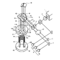
以下、本発明の実施の形態を図面にしたがって詳細に説明する。図1は本発明の絶対屈折率測定装置が備える光学系を示す概略斜視図である。また、図2は、図1に示す光学系内の光路を説明する模式図である。 Hereinafter, embodiments of the present invention will be described in detail with reference to the drawings. FIG. 1 is a schematic perspective view showing an optical system provided in the absolute refractive index measuring apparatus of the present invention. FIG. 2 is a schematic diagram for explaining an optical path in the optical system shown in FIG.
本発明の絶対屈折率測定装置10は、図1、図2に示すように、波長の異なる複数のレーザ光を出射可能な多波長レーザ光源1と、当該多波長レーザ光源1から出射されたレーザ光を二光束に分割する無偏光ビームスプリッタ3と、分割されたレーザ光がともに入射され、各レーザ光をそれぞれ真空領域と被測定サンプル領域とに導入するとともに、両領域を通過したレーザ光と後述の基準レーザ光との干渉光を生成する干渉光学回路4を備える。
As shown in FIGS. 1 and 2, the absolute refractive
上記多波長レーザ光源1は、Heガス及びNeガスが封止された励起管と当該励起管の両端に配置された出力側ミラーと全反射ミラーを有し、当該全反射ミラーと励起管との光学的距離を変化させることで、543nm、594nm、604nm、612nm、及び633nmの各波長のレーザ光を同一の出射口から選択的に出射できる構成になっている。 The multi-wavelength laser light source 1 has an excitation tube sealed with He gas and Ne gas, output side mirrors and total reflection mirrors arranged at both ends of the excitation tube, and includes the total reflection mirror and the excitation tube. By changing the optical distance, laser light having wavelengths of 543 nm, 594 nm, 604 nm, 612 nm, and 633 nm can be selectively emitted from the same emission port.
上記多波長レーザ光源1から水平方向に出射されたレーザ光は、後述の偏光ビームスプリッタ41でのレーザ光の分割を可能とするために、1/2波長板2により偏光角を45度にされた後、キューブ型の無偏光ビームスプリッタ3に入射し、当該無偏光ビームスプリッタ3内を直進するレーザ光と、入射方向に対して水平に90度の方向に進行するレーザ光との二光束に分割される。
The laser light emitted in the horizontal direction from the multi-wavelength laser light source 1 has a polarization angle of 45 degrees by the half-
また、無偏光ビームスプリッタ3から、上記直進レーザ光の進行方向に所定距離だけ離れた位置には、上記直進レーザ光の進行方向を上記無偏光ビームスプリッタ3で90度の方向に反射されたレーザ光と同一方向に変化させるミラー5が設けられる。すなわち、上記多波長レーザ光源1から出射されたレーザ光は、無偏光ビームスプリッタ3とミラー5により、同一方向に進行する平行なレーザ光に分割され、両レーザ光は上記干渉光学回路4に入射される。なお、以下では、ミラー5により進行方向が90度変化したレーザ光を真空側レーザ光L1と記述し、上記無偏光ビームスプリッタ3により、進行方向が90度変化したレーザ光をサンプル側レーザ光L2と記述する。
In addition, a laser beam which is reflected by the
上記干渉光学回路4は、キューブ型の偏光ビームスプリッタ41と、当該偏光ビームスプリッタ41を直進したレーザ光の進行方向を鉛直下方に変化させるミラー42と、前記偏光ビームスプリッタ41の上方に配置され、鉛直下方から入射するレーザ光を、所定の基準点に対して点対称の位置で鉛直下方に向けて折り返すコーナキューブ46とを備える。また、偏光ビームスプリッタ41の上方及び下方、並びにミラー42の下方にはレーザ光が2回通過すると偏光角を90度変化させる1/4波長板43、44、45が設けられている。
The interference optical circuit 4 is disposed above the
図2に示すように、上記干渉光学回路4に入射した真空側レーザ光L1は、偏光ビームスプリッタ41において、例えば、直進するs偏光(横)成分と入射方向に対して90度の方向に反射されるp偏光(縦)成分に分割される。
As shown in FIG. 2, the vacuum laser beam L1 incident on the interference optical circuit 4 is reflected by the
真空側レーザ光L1の偏光ビームスプリッタ41を直進する成分である真空側基準レーザ光L1Aは、ミラー42によって鉛直下方に反射され、後に詳述する測定部6の上面を構成するガラス板で構成される固定ステージ61に到達する。当該固定ステージ61の真空側基準レーザ光L1Aが入射する位置にはミラー加工が成されており、真空側基準レーザ光L1Aは固定ステージ61の上面で鉛直上方に反射される。この鉛直上方に反射された真空側基準レーザ光L1Aは、ミラー42を経て再び偏光ビームスプリッタ41に入射する。このとき、真空側基準レーザ光L1Aは、1/4波長板43を2回通過したことで偏光角が90度変化しており、偏光ビームスプリッタ41において鉛直上方に反射される。
The vacuum-side reference laser light L1A, which is a component of the vacuum-side laser light L1 that travels straight through the
そして、上記コーナキューブ46に到達し、当該コーナキューブ46において鉛直下方に進行方向が変化した真空側基準レーザ光L1Aは、再度、偏光ビームスプリッタ41に入射するが、1/4波長板45の通過により偏光角が90度変化しているため、偏光ビームスプリッタ41を直進して再び固定ステージ61に到達する。固定ステージ61の当該位置も上述と同様にミラー加工が成されており、真空側基準レーザ光L1Aは鉛直上方に反射され、1/4波長板44の通過により偏光角が90度変化した真空側基準レーザ光L1Aは、偏光ビームスプリッタ41において、当該干渉光学回路4に入射されてきた方向に反射される。なお、真空側レーザ光L1が入出射する偏光ビームスプリッタ41の入出射面41aにおいて、真空側レーザ光L1の入射位置と出射位置とは、上記コーナキューブ46による反射により、異なる水平面に位置にすることになる。すなわち、偏光ビームスプリッタ41から出射された真空側レーザ光L1の光路上に、上記無偏光ビームスプリッタ3やミラー5が位置していない。
Then, the vacuum side reference laser light L1A that has reached the
一方、偏光ビームスプリッタ41において、入射方向に対して90度の方向(ここでは、鉛直下方)に反射された、真空側レーザ光L1のp偏光成分である真空側測長レーザ光L1Bは、真空側基準レーザ光L2Aと通過順序は異なるが、同一の光学素子を通過して真空側基準レーザ光L1Aの出射位置と同一の位置から出射される。
On the other hand, in the
この真空側測長レーザ光L1Bの光路において、固定ステージ61の真空側測長レーザ光L1Bが到達する位置に透明な光導入窓61aが設けられており、真空側測長レーザ光L1Bは、当該光導入窓61aを介して真空領域63に導入されて測定部6の下端に設けられたミラーからなる移動ステージ62の上面で鉛直上方に反射される。
In the optical path of the vacuum side length measuring laser beam L1B, a transparent
すなわち、真空側基準レーザ光L1Aの光路長と真空側測長レーザ光L1Bの光路長とは、固定ステージ61の上面から移動ステージ62の上面までの光学的距離の4倍(2往復)だけ異なる。
In other words, the optical path length of the vacuum-side reference laser beam L1A and the optical path length of the vacuum-side measurement laser beam L1B differ by four times (two reciprocations) the optical distance from the upper surface of the fixed
このように、真空側基準レーザ光L1Aと真空側測長レーザ光L1Bとが畳重した状態で偏光ビームスプリッタ41から出射された真空側レーザ光L1は、偏光角45度のレーザ光が通過できるよう配置した偏光板47を通過することで、同一偏光成分の真空側基準レーザ光L1Aと真空側測長レーザ光L1Bが畳重した状態となり、上記光路差に応じた光強度を有する干渉光となる。
As described above, the vacuum side laser beam L1 emitted from the
また、サンプル側レーザ光L2についても、真空側レーザ光L1と同様に、上記干渉光学回路4をサンプル側基準レーザ光L2Aとサンプル側測長レーザ光L2Bとに分割されて通過し、当該サンプル側基準レーザ光L2Aとサンプル側測長レーザ光L2Bは、偏光ビームスプリッタ41の上記真空側レーザ光L1の出射位置とは異なる同一位置から出射される。このとき、サンプル側基準レーザ光L2Aは固定ステージ61の上面のミラー加工部で反射され、また、サンプル側測長レーザL2Bは、固定ステージ61の光導入窓61bを介してサンプル領域64に導入された後、移動ステージ62の上面で反射される。このため、干渉光学回路4から出射されるサンプル側レーザ光L2は、固定ステージ61の上面から移動ステージ62の上面までの光学的距離の4倍(2往復)の光路差に応じた光強度を有する干渉光となる。
Similarly to the vacuum side laser beam L1, the sample side laser beam L2 passes through the interference optical circuit 4 while being divided into the sample side reference laser beam L2A and the sample side length measuring laser beam L2B. The reference laser beam L2A and the sample side length measuring laser beam L2B are emitted from the same position different from the emission position of the vacuum side laser beam L1 of the
上述のようにして、干渉光学回路4から出射された真空側レーザ光L1、及び、サンプル側レーザ光L2は、ミラー7等を介して光センサ8a、8bに入力され光強度が検知される。
As described above, the vacuum side laser light L1 and the sample side laser light L2 emitted from the interference optical circuit 4 are input to the
なお、図2の例では、上記無偏光ビームスプリッタ3の多波長レーザ光源1側に、さらに無偏光ビームスプリッタ9を設けるとともに、当該無偏光ビームスプリッタ9において分割されたレーザ光の光強度を検知する光センサ8cを設け、多波長レーザ光源1から出力されるレーザ光の強度を確認できるようにしている。
In the example of FIG. 2, a non-polarizing beam splitter 9 is further provided on the multi-wavelength laser light source 1 side of the
また、本発明の絶対屈折率測定装置10では、上述の波長板2、43、44、45及び偏光ビームスプリッタ41として、上記多波長レーザ光源1が出射するレーザ光の波長範囲において、波長依存性の小さい偏光光学素子を採用している。
In the absolute refractive
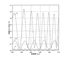
図3に、上記構成の絶対屈折率測定装置10において、移動ステージ62を下方に移動させているときに光センサ8bから出力される出力信号を示す。図3において、横軸は移動ステージ62の移動量に相当する経過時間であり、縦軸は光センサ8bの出力信号である。また、図中の一点鎖線A、破線B、実線Cは、それぞれ、633nm、594nm、543nmの波長に対する出力信号である。
FIG. 3 shows an output signal output from the
多波長レーザ光源1から出射されるレーザ光の強度が波長により異なるため、各波長における出力信号の大きさに差が見られるが、いずれの波長においても干渉光の強度変化が測定される。したがって、図3に示す干渉光の強度変化の波数を計数することで、多波長レーザ光源1が出力する波長範囲において、絶対屈折率の測定が可能である。 Since the intensity of the laser light emitted from the multi-wavelength laser light source 1 varies depending on the wavelength, there is a difference in the magnitude of the output signal at each wavelength, but the intensity change of the interference light is measured at any wavelength. Therefore, the absolute refractive index can be measured in the wavelength range output by the multi-wavelength laser light source 1 by counting the wave number of the intensity change of the interference light shown in FIG.
ここで、測定部6の構成について説明する。測定部6は、上端に上面が水平に設けられた例えば円盤状の上記固定ステージ61を備え、下端に当該固定ステージ61の上面と平行な上面を有し、上下方向に移動可能に設けられた円盤状の上記移動ステージ62を備える。
Here, the configuration of the
上記真空領域63は、上下面が固定ステージ61及び移動ステージ62で閉塞され、かつ、側面が上記移動ステージ62の移動に伴い伸縮可能な例えばジャバラ状の側壁で閉塞される略円柱状の空間として構成され、図示しない真空ポンプにより、内部が1atm程度の真空状態に保持されている。
The
また、上記移動ステージ62は、固定ステージ61上面と移動ステージ62上面との平行状態を保持したまま上下に移動させる移動ステージ駆動機構11に連結されている。
The moving
例えば、図4に示すように、上記移動ステージ駆動機構11は、テーブル12上に固定されたフレーム111の上端に、モータ等の駆動手段112が支持され、当該駆動手段112の下方に当該駆動手段112の回転駆動力を上下方向の駆動力に変換するギア等の駆動伝達手段113が設けられる。
For example, as shown in FIG. 4, the moving
上記駆動伝達手段113には、上下方向に延びる柱状の上下動アーム115が連結されており、この上下動アーム115の下端に、支持部材116を介して移動ステージ62の外縁部が固定される。
A columnar
また、上記上下動アーム115は、テーブル12に設けられたパイプ状の案内手段114に挿通されており、移動ステージ62は、水平方向のブレを生じることなく、昇降するようになっている。
The
一方、固定ステージ61の外縁部には、被測定液Sが固定ステージ61の上面に侵入することを防止する側壁65が設けられている。そして、絶対屈折率測定の際には、上記測定部6を、図示しない温度調整手段により液温が一定に保持される被測定液Sが収容された容器66内に、被測定液Sの液面が上記固定ステージ61の上面以上に位置するまで浸漬させる。
On the other hand, a
これにより、固定ステージ61と移動ステージ62の間の真空領域を除く領域に、被測定液Sが充填された上記サンプル領域64が構成される。
As a result, the
なお、上記光学系は、少なくとも、偏光板47を除く干渉光学回路4を、適宜、支持部材等を介して、測定部6の上方で上記フレーム111に支持させればよく、これら以外の光学素子は、上記テーブル12上などの任意の位置に配置すればよい。加えて、上記固定ステージ61は、側壁65がテーブル12又はフレーム111に固定されることにより支持されている。
In the optical system, at least the interference optical circuit 4 excluding the
また、上記移動ステージ駆動機構11としては、移動ステージ62を上下動可能であれば任意の構成を採用することができるが、上述のように、移動ステージ62が水平方向のブレや振動を防止できる構成であることが好ましい。
As the moving
以上説明したように、上記絶対屈折率測定装置10は、偏光光学素子を使用した光学回路を用いて、測定部6に入射する全光路、すなわち、真空側基準レーザ光L1A、真空側測長レーザ光L1B、サンプル側基準レーザ光L2A、及びサンプル側測長レーザ光L2Bをそれぞれ点対称の位置関係で2往復させている。このため、仮に、何らかの要因により移動ステージ62の上面が上記固定ステージ61の上面に対して傾斜した場合であっても、この傾きを吸収することが可能である。
As described above, the absolute refractive
また、上記コーナキューブ46は、下方から入射したレーザ光を、常に、コーナキューブ46の中心に対して点対象の位置に折り返す。すなわち、上記絶対屈折率測定装置10は、測定中に何らかの要因で光学系が振動した場合でも、上記全光路の点対称の位置関係を保持することができるため、振動の影響を受けにくくなっている。
Further, the
さて、上記のようにして被測定液Sに測定部6を浸漬した状態で、多波長レーザ光源1から、例えば、波長633nmのレーザ光を出射させ、移動ステージ62を移動ステージ駆動機構11により、例えば、下方に移動させると、移動ステージ62が移動中に光センサ8a,8bに入射される真空側レーザ光L1及びサンプル側レーザ光L2は、移動ステージの移動量に応じて明暗の強度変化を繰り返すことになる。
Now, with the measuring
この強度変化は、光センサ8a、8bの出力信号として、図2に示す計数器21に入力される。計数器21は入力された信号のフリンジ数を計数する。このフリンジ数の計数は、移動ステージ62が移動を開始してから停止するまでの間の任意の期間にわたって継続される。背景技術において説明したように、フリンジ数は移動ステージ62の移動量に依存するので、移動ステージ62の移動開始位置、及び停止位置は任意である。
This intensity change is input to the
上記計数器21は、図5に示すように、各光センサ8ごとに、出力信号を所定の信号レベルまで増幅するアンプ211と、出力信号のピークやゼロクロス点(光センサの出力信号をサイン波と看做した場合に位相0度に相当する位置)等を検出する比較器212と、当該比較器212の検出結果に基づいてフリンジ数を計数するカウンタ213を備えている。
As shown in FIG. 5, the
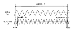
上記フリンジ数は、任意の方法により計数すればよいが、本実施の形態では、移動ステージ62の移動量が小さくなるように、以下の方法を採用している。すなわち、図6に示すように、真空側レーザ光L1の光強度を検出する光センサ8aの任意のゼロクロス点を始点tsとし、光センサ8aに対応するカウンタ値が所定値nとなるゼロクロス点を終点teとする。
The number of fringes may be counted by an arbitrary method, but in the present embodiment, the following method is adopted so that the moving amount of the moving
上記始点tsと終点teの間の計数期間Tにおいて、サンプル側レーザ光L2の光強度を検出する光センサ8bのフリンジ数をカウントする。このようにして計数したカウント値だけでは、絶対屈折率の精度は上記所定値nの1/桁数となる。
In the counting period T between the start point ts and the end point te, the number of fringes of the
そこで、本実施の形態では、始点ts、及び終点teにおける光センサ8bの出力信号のアナログ値から、上記カウンタ213が、サンプル側レーザ光L2のフリンジ数としてカウントできない1に満たない部分、すなわち、小数点以下の波数(以下、端数という。)を求めている。このような端数は、上記アナログ値と光センサ8bの出力信号の振幅値との比率から演算される位相から求めることができる。なお、本実施の形態ではこの演算をA/Dコンバータ214と後述の演算手段22とで行っている。なお、上記演算により2つの位相が得られるが、正しい位相がどちらであるかの判断は、光センサ8bの出力信号のゼロクロス間隔の1/4以下の時間に、再度光センサ8bのアナログ値を取得し、当該アナログ値と先に取得したアナログ値との大小関係により判断している。
Therefore, in the present embodiment, from the analog value of the output signal of the
このように、光センサ8の出力信号から、端数を含めたフリンジ数を計数することで、同一の移動量でより精度の高い絶対屈折率を求めることができる。 Thus, by counting the number of fringes including the fraction from the output signal of the optical sensor 8, a more accurate absolute refractive index can be obtained with the same movement amount.
以上のようにして計数された真空側レーザ光L1とサンプル側レーザ光L2のフリンジ数(上記端数を含む)は、図2及び図5に示すマイクロコンピュータ等からなる演算手段22に入力される。上記サンプル領域64に充填された被測定液Sの絶対屈折率は、背景技術で説明したように、(サンプル側レーザ光L2のフリンジ数)/(真空側レーザ光L1のフリンジ数)として求めることができるので、上記演算手段22は、(サンプル側レーザ光L2のフリンジ数+始点端数X1+終点端数X2)/(真空側レーザ光L1のフリンジ数)を演算し、波長633nmのレーザ光に対する被測定液Sの絶対屈折率を取得する。
The fringe numbers (including the fractions) of the vacuum-side laser light L1 and the sample-side laser light L2 counted as described above are input to the calculation means 22 including a microcomputer shown in FIGS. As described in the background art, the absolute refractive index of the liquid S to be measured filled in the
なお、このレーザ光の正確な波長は、例えば、上記測定の前または後に多波長レーザ光源1と1/2波長板2との間で、カップリングデバイス等を用いてレーザ光を取出し、この取出したレーザ光を光波長計により測定する。
The exact wavelength of this laser beam is obtained, for example, by using a coupling device or the like between the multi-wavelength laser light source 1 and the half-
このような処理を、上記多波長レーザ光源1が選択可能な全波長に対して行い、各波長に対する被測定液Sの絶対屈折率を取得する。そして、上記演算手段22は、各波長に対する被測定液Sの絶対屈折率から、絶対屈折率と波長の関係式を、例えば、3次の回帰式として導出し、この関係式に基づいて、ナトリウムD線(波長589.3nm)に対する絶対屈折率を演算する。 Such processing is performed for all wavelengths that can be selected by the multi-wavelength laser light source 1, and the absolute refractive index of the liquid S to be measured for each wavelength is acquired. Then, the calculating means 22 derives a relational expression between the absolute refractive index and the wavelength as, for example, a cubic regression expression from the absolute refractive index of the liquid S to be measured for each wavelength, and based on this relational expression, sodium The absolute refractive index for the D line (wavelength 589.3 nm) is calculated.
具体例として、被測定液Sに純水とトリデカン(液温20℃)を用いた場合の各波長における測定結果を表1に示す。 As a specific example, Table 1 shows the measurement results at each wavelength when pure water and tridecane (liquid temperature 20 ° C.) are used as the liquid S to be measured.

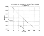
また、上記表1の結果に基づいて、絶対屈折率と波長の関係式を3次の回帰式として求め、この回帰式に基づいて求めたナトリウムD線(波長589.3nm)に対する絶対屈折率は、純水が1.333356、トリデカンが1.425957である。なお、上記各絶対屈折率の測定値は、10-6オーダの良好な再現性が得られている。参考までに、文献値によれば、純水の絶対屈折率は1.33335となっている("Handbook of Chemistry and Physics" 56th Edition, CRC Press)。 Moreover, based on the result of the said Table 1, the absolute refractive index with respect to the sodium D line | wire (wavelength 589.3nm) calculated | required as a cubic regression equation was calculated | required as a relationship equation of an absolute refractive index and a wavelength, Pure water is 1.333356 and tridecane is 1.425957. The measured values of the respective absolute refractive indexes have good reproducibility on the order of 10 −6 . For reference, according to literature values, the absolute refractive index of pure water is 1.33335 ("Handbook of Chemistry and Physics" 56th Edition, CRC Press).
なお、純水の絶対屈折率の周波数依存性を示すグラフを図7に示す。また、上記では3次の回帰式を使用したが、回帰式の次数を特に限定するものではない。 In addition, the graph which shows the frequency dependence of the absolute refractive index of a pure water is shown in FIG. In the above description, a cubic regression equation is used. However, the order of the regression equation is not particularly limited.
以上説明したように、本発明の絶対屈折率測定装置10によれば、各波長における被測定液の絶対屈折率を精度良く測定することができる上、測定波長を変更する場合に、光源及び光学素子の交換、並びに光学回路の調整が必要なく、光源の波長変更に伴う測定誤差を考慮する必要がない。
As described above, according to the absolute refractive
また、上記各波長での絶対屈折率の値を用いて被測定液の絶対屈折率の波長依存性を導出することにより、被測定液の任意の波長におけるの絶対屈折率を精度良く求めることができる。 Further, by deriving the wavelength dependence of the absolute refractive index of the liquid to be measured using the absolute refractive index values at the respective wavelengths, the absolute refractive index at an arbitrary wavelength of the liquid to be measured can be accurately obtained. it can.
なお、上記実施の形態で説明した偏光干渉光学回路4の構成は、具体例を示したものであり、本願の技術的範囲を制限するものではない。本願の効果を奏する範囲において、任意に設計することが可能である。 The configuration of the polarization interference optical circuit 4 described in the above embodiment shows a specific example, and does not limit the technical scope of the present application. It is possible to design arbitrarily within the range where the effects of the present application are achieved.
また、上記では測定部6の構成を、測定部6の下端に支持した移動ステージ62を固定ステージ61に対して移動させる構成として説明したが、この構成に限るものではない。すなわち、真空領域の光路長変動量に対応する干渉光のフリンジ数と、サンプル領域の光路長変動量に対応する干渉光のフリンジ数とが計数できる構成であれば良く、例えば、測定部6の下端に固定した固定ステージに対して、当該固定ステージの上方に設けた移動ステージを移動させる構成を採用してもよい。
In the above description, the configuration of the
さらに、上記サンプル側基準レーザ光、及び、サンプル側測長レーザ光も、上記光路に限定されるものではなく、上記従来技術に記載された構成のように、サンプル側基準レーザ光として真空領域とサンプル領域を通過させたレーザ光を使用する構成など、本発明の効果を奏する範囲において任意の構成を採用することができる。 Further, the sample-side reference laser light and the sample-side length measurement laser light are not limited to the optical path, and as in the configuration described in the conventional technique, the sample-side reference laser light has a vacuum region and Arbitrary configurations can be adopted within a range where the effects of the present invention can be achieved, such as a configuration using laser light that has passed through the sample region.
例えば、測定部の構成を上記固定ステージと移動ステージの間を全て真空領域とし、サンプル側測長レーザ光が到達する位置に透明な光通過窓を設けるとともに、移動ステージと当該移動ステージの下方に当該光通過窓を通過したレーザ光を鉛直上方に反射する上記固定ステージとの距離が固定である固定ミラーを設け、移動ステージと固定ミラーの間にサンプル領域を設ける構成とすることができる。 For example, the structure of the measurement unit is a vacuum region between the fixed stage and the moving stage, and a transparent light passage window is provided at a position where the sample-side length measuring laser beam reaches, and the moving stage and the moving stage are below. A fixed mirror having a fixed distance from the fixed stage that reflects laser light that has passed through the light passing window vertically upward may be provided, and a sample region may be provided between the moving stage and the fixed mirror.
すなわち、サンプル側測長レーザ光として真空領域とサンプル領域とを通過させたレーザ光を使用し、真空側測長レーザ光として真空領域のみを通過させたレーザ光を使用する。この構成によっても、移動ステージが移動時のサンプル領域の光路長変動量に対応するフリンジ数を計数することが可能であり、絶対屈折率を測定することが可能である。 That is, laser light that has passed through the vacuum region and the sample region is used as the sample-side length measurement laser light, and laser light that has been passed through only the vacuum region is used as the vacuum-side length measurement laser light. Also with this configuration, it is possible to count the number of fringes corresponding to the amount of fluctuation in the optical path length of the sample region when the moving stage moves, and it is possible to measure the absolute refractive index.
本発明は、被測定液の任意の波長における絶対屈折率を精度良く求めることができ、液体の絶対屈折率測定装置として有用である。 INDUSTRIAL APPLICATION This invention can obtain | require the absolute refractive index in arbitrary wavelengths of a to-be-measured liquid accurately, and is useful as an absolute refractive index measuring apparatus of a liquid.
1 多波長レーザ
2 1/2波長板
3、9 無偏光ビームスプリッタ
4 偏光光学回路
5、7 ミラー
6 測定部
8 光センサ
10 絶対屈折率測定装置
11 移動ステージ駆動機構
21 計数器
22 演算手段
41 偏光ビームスプリッタ
42 ミラー
43、44,45 1/4波長板
61 固定ステージ
62 移動ステージ
63 真空領域
64 サンプル領域
S 被測定液
DESCRIPTION OF SYMBOLS 1
Claims (2)
前記レーザ光源から出射されるレーザ光を、真空領域を通過させる真空側レーザ光と、被測定液が充填されたサンプル領域を通過させるサンプル側レーザ光とに分割するビームスプリッタと、
前記両領域を通過前に前記分割された各レーザ光からさらに分割された基準レーザ光と、前記両領域を通過後の各レーザ光との干渉光をそれぞれ生成する偏光干渉光学回路と、
前記各干渉光の光強度を検知する光センサと、
前記真空領域及びサンプル領域の前記レーザ光の光路長を変動させたときに前記光センサが検知する前記各干渉光の強度変化の波数をそれぞれ計数する計数器とを備え、
前記偏光干渉光学回路は、前記レーザ光源から出射される全ての波長のレーザ光に対して同一の偏光光学素子を用いる液体の絶対屈折率測定装置。 A laser light source that selectively emits a plurality of laser beams having different wavelengths from the same emission port;
A beam splitter that divides laser light emitted from the laser light source into vacuum side laser light that passes through a vacuum region and sample side laser light that passes through a sample region filled with a liquid to be measured;
A polarization interference optical circuit that generates a reference laser beam further divided from each of the divided laser beams before passing through both the regions, and an interference light between each laser beam after passing through both the regions;
An optical sensor for detecting the light intensity of each interference light;
A counter that respectively counts the wave number of the intensity change of each interference light detected by the optical sensor when the optical path length of the laser light in the vacuum region and the sample region is changed,
The polarization interference optical circuit is a liquid absolute refractive index measurement device that uses the same polarization optical element for all wavelengths of laser light emitted from the laser light source.
Priority Applications (1)
| Application Number | Priority Date | Filing Date | Title |
|---|---|---|---|
| JP2004110066A JP4314390B2 (en) | 2004-04-02 | 2004-04-02 | Liquid absolute refractive index measuring device |
Applications Claiming Priority (1)
| Application Number | Priority Date | Filing Date | Title |
|---|---|---|---|
| JP2004110066A JP4314390B2 (en) | 2004-04-02 | 2004-04-02 | Liquid absolute refractive index measuring device |
Publications (2)
| Publication Number | Publication Date |
|---|---|
| JP2005292033A true JP2005292033A (en) | 2005-10-20 |
| JP4314390B2 JP4314390B2 (en) | 2009-08-12 |
Family
ID=35325113
Family Applications (1)
| Application Number | Title | Priority Date | Filing Date |
|---|---|---|---|
| JP2004110066A Expired - Lifetime JP4314390B2 (en) | 2004-04-02 | 2004-04-02 | Liquid absolute refractive index measuring device |
Country Status (1)
| Country | Link |
|---|---|
| JP (1) | JP4314390B2 (en) |
Cited By (2)
| Publication number | Priority date | Publication date | Assignee | Title |
|---|---|---|---|---|
| JP2009014487A (en) * | 2007-07-04 | 2009-01-22 | National Institute Of Advanced Industrial & Technology | Refractive index measurement method and apparatus |
| WO2019009404A1 (en) * | 2017-07-06 | 2019-01-10 | 浜松ホトニクス株式会社 | Optical module |
-
2004
- 2004-04-02 JP JP2004110066A patent/JP4314390B2/en not_active Expired - Lifetime
Cited By (18)
| Publication number | Priority date | Publication date | Assignee | Title |
|---|---|---|---|---|
| JP2009014487A (en) * | 2007-07-04 | 2009-01-22 | National Institute Of Advanced Industrial & Technology | Refractive index measurement method and apparatus |
| WO2019009404A1 (en) * | 2017-07-06 | 2019-01-10 | 浜松ホトニクス株式会社 | Optical module |
| WO2019009401A1 (en) * | 2017-07-06 | 2019-01-10 | 浜松ホトニクス株式会社 | OPTICAL MODULE |
| JP6496463B1 (en) * | 2017-07-06 | 2019-04-03 | 浜松ホトニクス株式会社 | Optical module |
| CN110799817A (en) * | 2017-07-06 | 2020-02-14 | 浜松光子学株式会社 | Optical assembly |
| JPWO2019009401A1 (en) * | 2017-07-06 | 2020-04-30 | 浜松ホトニクス株式会社 | Optical module |
| US11054309B2 (en) | 2017-07-06 | 2021-07-06 | Hamamatsu Photonics K.K. | Optical module |
| US11067380B2 (en) | 2017-07-06 | 2021-07-20 | Hamamatsu Photonics K.K. | Optical module |
| US11187579B2 (en) | 2017-07-06 | 2021-11-30 | Hamamatsu Photonics K.K. | Optical device |
| US11209260B2 (en) | 2017-07-06 | 2021-12-28 | Hamamatsu Photonics K.K. | Optical module having high-accuracy spectral analysis |
| JP7233365B2 (en) | 2017-07-06 | 2023-03-06 | 浜松ホトニクス株式会社 | optical module |
| US11624605B2 (en) | 2017-07-06 | 2023-04-11 | Hamamatsu Photonics K.K. | Mirror unit and optical module |
| US11629947B2 (en) | 2017-07-06 | 2023-04-18 | Hamamatsu Photonics K.K. | Optical device |
| US11629946B2 (en) | 2017-07-06 | 2023-04-18 | Hamamatsu Photonics K.K. | Mirror unit and optical module |
| US11635290B2 (en) | 2017-07-06 | 2023-04-25 | Hamamatsu Photonics K.K. | Optical module |
| US11879731B2 (en) | 2017-07-06 | 2024-01-23 | Hamamatsu Photonics K.K. | Mirror unit and optical module |
| US12152878B2 (en) | 2017-07-06 | 2024-11-26 | Hamamatsu Photonics K.K. | Mirror unit and optical module |
| US12298132B2 (en) | 2017-07-06 | 2025-05-13 | Hamamatsu Photonics K.K. | Optical device |
Also Published As
| Publication number | Publication date |
|---|---|
| JP4314390B2 (en) | 2009-08-12 |
Similar Documents
| Publication | Publication Date | Title |
|---|---|---|
| JP5226078B2 (en) | Interferometer device and method of operating the same | |
| CN102192896B (en) | Optical interference measuring method and optical interference measuring apparatus | |
| CN102183234B (en) | Method and device for measuring frequency scanning absolute distance based on femtosecond optical frequency comb | |
| Lee et al. | Optical heterodyne grating interferometry for displacement measurement with subnanometric resolution | |
| CN102252764B (en) | Laser wavelength real-time measurement device | |
| JP5511163B2 (en) | Distance measuring method and apparatus by light wave interference | |
| US8687204B2 (en) | Method and apparatus for measuring refractive index based on a ratio between a number of second fringes divided by a difference of the number of second fringes minus a number of first fringes | |
| JP5216465B2 (en) | Displacement measuring device and displacement measuring method | |
| JP2015010921A (en) | Refractive index measurement method, refractive index measurement apparatus, and optical element manufacturing method | |
| JP2017003434A (en) | Refractive index measurement method, measurement device, and optical element manufacturing method | |
| JP2024017359A (en) | Optical devices and spectroscopy | |
| RU155509U1 (en) | LASER-INTERFERENCE HYDROPHONE WITH THERMOSTABILIZATION SYSTEM | |
| JP2015099133A (en) | Measurement method and measurement device for thickness | |
| CN109520428A (en) | A kind of displacement measurement optical system | |
| JP4314390B2 (en) | Liquid absolute refractive index measuring device | |
| JP2002333371A (en) | Wavemeter | |
| JP2015105850A (en) | Refractive index measuring method, refractive index measuring apparatus, and optical element manufacturing method | |
| TW200928301A (en) | Apparatus for measuring displacement by using wavelength-modulated heterodyne grating interferometer | |
| JP6157241B2 (en) | Refractive index measuring method, refractive index measuring apparatus, and optical element manufacturing method | |
| JP5704897B2 (en) | Interference measurement method and interference measurement apparatus | |
| CN104792269A (en) | Calculation method for optical fiber end face height insensitive to linear phase-shift errors | |
| CN116952901A (en) | Experimental device, experimental method and elongation measurement device based on tilted fiber grating | |
| JP4247372B2 (en) | Refractive index measurement method and apparatus | |
| JP2705752B2 (en) | Method of measuring refractive index and method of measuring property characteristics | |
| JPS60500733A (en) | Dynamic mirror alignment control device |
Legal Events
| Date | Code | Title | Description |
|---|---|---|---|
| A621 | Written request for application examination |
Free format text: JAPANESE INTERMEDIATE CODE: A621 Effective date: 20070117 |
|
| A521 | Request for written amendment filed |
Free format text: JAPANESE INTERMEDIATE CODE: A821 Effective date: 20070117 |
|
| A131 | Notification of reasons for refusal |
Free format text: JAPANESE INTERMEDIATE CODE: A131 Effective date: 20081126 |
|
| A521 | Request for written amendment filed |
Free format text: JAPANESE INTERMEDIATE CODE: A523 Effective date: 20090116 |
|
| TRDD | Decision of grant or rejection written | ||
| A01 | Written decision to grant a patent or to grant a registration (utility model) |
Free format text: JAPANESE INTERMEDIATE CODE: A01 Effective date: 20090422 |
|
| A01 | Written decision to grant a patent or to grant a registration (utility model) |
Free format text: JAPANESE INTERMEDIATE CODE: A01 |
|
| A61 | First payment of annual fees (during grant procedure) |
Free format text: JAPANESE INTERMEDIATE CODE: A61 Effective date: 20090428 |
|
| R150 | Certificate of patent or registration of utility model |
Ref document number: 4314390 Country of ref document: JP Free format text: JAPANESE INTERMEDIATE CODE: R150 Free format text: JAPANESE INTERMEDIATE CODE: R150 |
|
| FPAY | Renewal fee payment (event date is renewal date of database) |
Free format text: PAYMENT UNTIL: 20120529 Year of fee payment: 3 |
|
| FPAY | Renewal fee payment (event date is renewal date of database) |
Free format text: PAYMENT UNTIL: 20130529 Year of fee payment: 4 |
|
| R250 | Receipt of annual fees |
Free format text: JAPANESE INTERMEDIATE CODE: R250 |
|
| R250 | Receipt of annual fees |
Free format text: JAPANESE INTERMEDIATE CODE: R250 |
|
| R250 | Receipt of annual fees |
Free format text: JAPANESE INTERMEDIATE CODE: R250 |
|
| S533 | Written request for registration of change of name |
Free format text: JAPANESE INTERMEDIATE CODE: R313533 |
|
| R350 | Written notification of registration of transfer |
Free format text: JAPANESE INTERMEDIATE CODE: R350 |
|
| R250 | Receipt of annual fees |
Free format text: JAPANESE INTERMEDIATE CODE: R250 |
|
| R250 | Receipt of annual fees |
Free format text: JAPANESE INTERMEDIATE CODE: R250 |
|
| R250 | Receipt of annual fees |
Free format text: JAPANESE INTERMEDIATE CODE: R250 |
|
| R250 | Receipt of annual fees |
Free format text: JAPANESE INTERMEDIATE CODE: R250 |
|
| R250 | Receipt of annual fees |
Free format text: JAPANESE INTERMEDIATE CODE: R250 |
|
| R250 | Receipt of annual fees |
Free format text: JAPANESE INTERMEDIATE CODE: R250 |
|
| R250 | Receipt of annual fees |
Free format text: JAPANESE INTERMEDIATE CODE: R250 |
|
| EXPY | Cancellation because of completion of term |