JP2005291987A - Sample analyzer - Google Patents
Sample analyzer Download PDFInfo
- Publication number
- JP2005291987A JP2005291987A JP2004108846A JP2004108846A JP2005291987A JP 2005291987 A JP2005291987 A JP 2005291987A JP 2004108846 A JP2004108846 A JP 2004108846A JP 2004108846 A JP2004108846 A JP 2004108846A JP 2005291987 A JP2005291987 A JP 2005291987A
- Authority
- JP
- Japan
- Prior art keywords
- sample
- aerosol
- sensor
- sample analyzer
- specimen
- Prior art date
- Legal status (The legal status is an assumption and is not a legal conclusion. Google has not performed a legal analysis and makes no representation as to the accuracy of the status listed.)
- Pending
Links
Images

Landscapes
- Automatic Analysis And Handling Materials Therefor (AREA)
- Investigating Or Analysing Materials By Optical Means (AREA)
Abstract
Description
本発明は、検体容器に注入した液体試料の成分や状態を分析するための試料分析装置に関し、特に血液などの感染性試料を分析する際に、検体容器から漏出した液体試料がエアロゾルとなって装置外部に漏洩することを防止するものに関する。 The present invention relates to a sample analyzer for analyzing components and states of a liquid sample injected into a specimen container, and in particular, when analyzing an infectious sample such as blood, the liquid sample leaked from the specimen container becomes an aerosol. The present invention relates to a device that prevents leakage outside the apparatus.
従来の試料分析装置は、図6に示すように、検体容器2を回転させるためのスピンドルモータ4、検体容器2に注入された検体1に光ビームを照射するための光源手段5、検体1を透過した光ビームを検出するための受光手段6、検体容器2を収容するためのケース7などから構成される。
As shown in FIG. 6, the conventional sample analyzer includes a
分析方法としては、例えば検体1として血液を検体容器2に注入してスピンドルモータ4に装着し、スピンドルモータ4によって検体容器2を回転させつつ、光源手段5から出射した光ビームを検体1に照射し、検体1を透過した光ビームを受光手段6により検出することで、血液中の成分を分析する。ここで、検体容器2の反応室201内に特定の抗原と反応する抗体202を塗布しておけば、反応室201を透過する光ビームを検出することで特定の抗原の有無を判定することができる(例えば、特許文献1参照)。
As an analysis method, for example, blood is injected into the
ところが、上記構成では、血液などの検体1を注入した検体容器2を高速で回転させつつ分析を行うため、検体容器2に検体1を注入する際に検体1が検体容器2の検体注入孔203の周囲に付着していた場合や、検体容器2が万一破損していた場合などに、検体容器2の回転によって飛散した検体1がエアロゾル(液体が霧状あるいは粒状となり空気中を浮遊している状態)となって装置外に漏洩する恐れがある。特に血液などの生体試料を分析する場合には、その試料がたとえばB型肝炎など感染力の強いウィルスを含んでいる可能性があり、そのエアロゾルを操作者が吸入した場合には検体1中の病原体(ウィルスなど)に感染する危険性がある。
However, in the above configuration, since the analysis is performed while rotating the
そこで、図に示すように、装置内の空気を装置外に排出する排気ファン9とエアロゾルを捕集するためのフィルタ部材10を設け、万一検体容器2から検体1がエアロゾルとなって飛散しても、フィルタ部材10により飛散したエアロゾルを捕集しつつ、装置内の空気を排気ファン9により装置外に排出するように構成した試料分析装置が提案されている(特許文献2参照)。
しかしながら、前記従来の試料分析装置は、排気ファンやフィルタ部材を備えているとはいえ、検体容器2から漏出した検体1がエアロゾルとなって装置内に浮遊していることに操作者が気付かないまま検体容器着脱扉11を開いて検体容器2を取り出した場合、エアロゾルとして装置内に浮遊している検体1が検体容器着脱扉11から装置外に漏洩し、操作者が病原体に感染するといった事故が想定され、検体容器2から検体1が漏出した際の安全性という面で十分とはいえない。
However, although the conventional sample analyzer includes an exhaust fan and a filter member, the operator does not notice that the specimen 1 leaked from the
本発明は、上記従来の課題を解決するものであり、検体容器2から漏出しエアロゾルとなった検体1が装置外に漏出する危険性を飛躍的に低減することが可能な試料分析装置を提供することを目的とする。
The present invention solves the above-described conventional problems, and provides a sample analyzer that can drastically reduce the risk that the specimen 1 leaked from the
前記従来の課題を解決するために、本発明の試料分析装置は、液体試料を収集した検体容器を内部に収納した状態で、前記液体試料中の成分を分析するようにした分析装置であって、前記分析時に、装置内部に漏洩した前記液体試料によるエアロゾルを検出するセンサを設けたことを特徴とするものである。 In order to solve the above-described conventional problems, the sample analyzer of the present invention is an analyzer configured to analyze components in the liquid sample in a state where a sample container in which the liquid sample is collected is housed inside. In addition, a sensor is provided that detects aerosol from the liquid sample leaked into the apparatus during the analysis.
また本発明は、上記試料分析装置において、検体容器を装置本体内部へ出し入れする際に開閉する扉部材を備えており、さらに、前記センサが装置本体内にエアロゾルの存在を検知した場合に、前記扉部材が動作できないようにするロック機構を設けたことを特徴とするものである。 In the sample analyzer, the present invention further includes a door member that opens and closes when the sample container is taken in and out of the apparatus main body, and when the sensor detects the presence of aerosol in the apparatus main body, A lock mechanism is provided to prevent the door member from operating.
また、本発明の試料分析装置は、装置本体内の空気を装置外に排出するための排気ファンと、排出する空気中のエアロゾルを捕集するためのフィルタ部材をさらに備え、前記センサが装置内部のエアロゾルの存在を検知することに応じて、前記排気ファンを作動させるように構成したことを特徴とするものである。 The sample analyzer of the present invention further includes an exhaust fan for exhausting air inside the apparatus main body to the outside of the apparatus, and a filter member for collecting aerosol in the exhausted air, and the sensor is disposed inside the apparatus. The exhaust fan is operated in response to detecting the presence of the aerosol.
また、本発明の試料分析装置は、前記センサが装置内部におけるエアロゾルの存在を検知した後、所定の時間だけ前記排気ファンを駆動させた後に、前記ロック機構を解除するようにしたことを特徴とするものである。 The sample analyzer of the present invention is characterized in that the lock mechanism is released after the exhaust fan is driven for a predetermined time after the sensor detects the presence of aerosol in the apparatus. To do.
また、本発明の試料分析装置は、前記センサが装置内部におけるエアロゾルの存在を検知した後、前記センサがエアロゾルの濃度が下がったことを検知するまで前記排気ファンを駆動させ、その後、前記ロック機構を解除するようにしたことを特徴とするものである。 In the sample analyzer of the present invention, after the sensor detects the presence of aerosol in the apparatus, the exhaust fan is driven until the sensor detects that the concentration of the aerosol has decreased, and then the lock mechanism It is characterized by canceling.
また、本発明の試料分析装置は、前記センサを、発光素子と該発光素子からの光を受光する受光素子とから構成し、前記受光素子の受光量から装置内部のエアロゾルの存在を検知するようにしたことを特徴とするものである。 In the sample analyzer of the present invention, the sensor includes a light emitting element and a light receiving element that receives light from the light emitting element, and detects the presence of aerosol in the apparatus from the amount of light received by the light receiving element. It is characterized by that.
また、本発明の試料分析装置は、前記センサを検体容器の近傍に配置したことを特徴とするものである。 Moreover, the sample analyzer of the present invention is characterized in that the sensor is arranged in the vicinity of the sample container.
また、本発明の試料分析装置は、検体容器をディスク状に構成するとともに、前記分析装置は、前記ディスクを回転させて液体試料の分析を行うように構成してあり、前記センサのエアロゾル検出領域を前記ディスク盤面の外周部としたことを特徴とするものである。 In the sample analyzer of the present invention, the specimen container is configured in a disk shape, and the analyzer is configured to analyze the liquid sample by rotating the disk, and the aerosol detection area of the sensor Is the outer periphery of the disk board surface.
また、本発明の試料分析装置は、前記センサがエアロゾルの存在を検知したことを操作者に告知するようにしたことを特徴とするものである。 In the sample analyzer of the present invention, the operator is notified that the sensor detects the presence of aerosol.
本発明の試料分析装置によれば、検体容器の破損等により万一検体が検体容器から漏出し、エアロゾルとなって装置内に飛散しても、飛散したエアロゾルが装置外に漏洩することを防止し、また、装置内にエアロゾルとなった検体が浮遊していることに気付かずに操作者が検体容器着脱扉を開いてしまい、漏洩したエアロゾルを吸入して病原体に感染するといった事故を回避することができる。 According to the sample analyzer of the present invention, even if a specimen leaks out of the specimen container due to a breakage of the specimen container, etc., and becomes an aerosol, it is prevented from leaking out of the apparatus. In addition, the operator opens the specimen container attachment / detachment door without noticing that the aerosolized specimen is floating in the device, and avoids accidents such as inhaling the leaked aerosol and infecting pathogens. be able to.
以下に、本発明の試料分析装置について、その実施の形態を図面とともに詳細に説明する。なお、従来の試料分析装置と同一の機能を有する部分には同一の符号を付し、説明を省略する。
(実施の形態1)
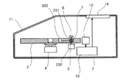
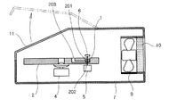
図1は、本発明の実施の形態1における試料分析装置の構成図である。本実施の形態における試料分析装置の構成は、従来の試料分析装置の構成に類似しているが、装置内部にエアロゾルを検知するエアロゾルセンサを備え、前記検体容器から液体試料が漏出したことを検知可能に構成した点で異なる。
Hereinafter, embodiments of the sample analyzer of the present invention will be described in detail with reference to the drawings. In addition, the same code | symbol is attached | subjected to the part which has the same function as the conventional sample analyzer, and description is abbreviate | omitted.
(Embodiment 1)
FIG. 1 is a configuration diagram of a sample analyzer according to Embodiment 1 of the present invention. The configuration of the sample analyzer in the present embodiment is similar to the configuration of a conventional sample analyzer, but an aerosol sensor that detects aerosol is provided inside the device and detects that a liquid sample has leaked from the specimen container. It differs in that it is configured as possible.
図1において、12は空気中に浮遊するエアロゾルを検出するためのエアロゾルセンサ、13は制御回路、14は装置の状態を操作者に知らせるための表示装置である。本実施の形態の試料分析装置を用いて分析を行う際、着脱可能な検体容器2に検体1を注入した後、装置に設けられた検体容器着脱扉11を開いて検体容器2を装置に装着する。次に、検体容器2はスピンドルモータ4により回転し、必要に応じて遠心分離等の処理を行った後、検体1を検体容器2内の反応室201に移送し、反応室内の抗体202と反応させる。そこで、光源手段5から出射した光ビームを反応室201に照射し、その透過光を受光手段6を用いて受光することで検体1と抗体202との反応状態を検出して分析を行う。
In FIG. 1, 12 is an aerosol sensor for detecting aerosol floating in the air, 13 is a control circuit, and 14 is a display device for notifying the operator of the state of the apparatus. When performing analysis using the sample analyzer of the present embodiment, after injecting the sample 1 into the
ここで、操作者が検体容器2に検体1を注入する際に検体1が検体注入孔203から溢れたり、また万一検体容器2が破損していたりした場合、検体容器2をスピンドルモータ4で回転させたときに検体容器2の表面に付着した、もしくは破損した検体容器2から漏出した検体1が遠心力により飛散し、エアロゾルとなって装置内を浮遊することとなる。
Here, when the operator injects the specimen 1 into the
そこで、本実施の形態の試料分析装置では、装置内に浮遊するエアロゾルをエアロゾルセンサ12で検出し、制御回路13を介して表示装置14に警告表示を行うことで検体1の漏出を操作者に知らせることが可能となり、操作者が装置内にエアロゾルとなった検体1が浮遊していることに気付かずに検体容器着脱扉11を開いてしまい、検体容器着脱扉11から流出したエアロゾルを吸入して病原体に感染するといった事故を回避することができる。
Therefore, in the sample analyzer of the present embodiment, the aerosol floating in the apparatus is detected by the
(実施の形態2)
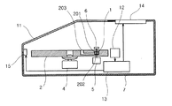
図2は、本発明の実施の形態2における試料分析装置の構成図である。本実施の形態における試料分析装置の構成は、上記実施の形態1の構成と類似しているが、検体容器着脱扉11にロック機構15を設けた点で異なる。
(Embodiment 2)
FIG. 2 is a configuration diagram of the sample analyzer according to the second embodiment of the present invention. The configuration of the sample analyzer in the present embodiment is similar to the configuration of the first embodiment, but differs in that a
図2において、実施の形態1と同様に分析動作中にエアロゾルセンサ12が、装置内に検体1が漏出したことを検知すると、制御回路13が、ロック機構15を作動させ、検体容器着脱扉11をロックして開かないようにする。
In FIG. 2, when the
このような構成をとることで、操作者が装置内にエアロゾルとなった検体1が浮遊していることに気付かずに検体容器着脱扉11を開いてしまい、検体容器着脱扉11から流出したエアロゾルを吸入して病原体に感染するといった事故を回避することができ、更に安全性を増すことができる。
By adopting such a configuration, the operator opens the sample container attaching / detaching
(実施の形態3)
図3は本発明の実施の形態3における試料分析装置の構成図である。本実施の形態における試料分析装置の構成は、上記実施の形態1もしくは実施の形態2に示した構成と類似しているが、装置内部の空気を装置外に排出する排気ファン9と、外部に排出する空気からエアロゾルを捕集するフィルタ部材10を備え、前記エアロゾルセンサ12が検体1の漏出を検知したときに、前記排気ファン9が作動し、装置内部のエアロゾルを前記フィルタ部材10にて捕集しつつ、装置内部の空気を外部に排出するように構成した点で異なる。このような構成をとることにより、検体容器2から検体1が漏出した際に、装置内に浮遊するエアロゾルを速やかに捕集することができ、更に安全性を高めることが可能となる。
(Embodiment 3)
FIG. 3 is a configuration diagram of a sample analyzer according to Embodiment 3 of the present invention. The configuration of the sample analyzer in the present embodiment is similar to the configuration shown in the first embodiment or the second embodiment, but the
また、本実施の形態の構成による試料分析装置において、エアロゾルセンサ12が検体1の漏出を検知した後、排気ファン9が一定時間動作した後に、表示装置14の警告表示及び/またはロック機構15の作動を解除するように構成することにより、装置内のエアロゾルの捕集が完了した後、速やかに次の分析作業を継続することが可能となる。
Further, in the sample analyzer according to the configuration of the present embodiment, after the
この際の表示装置14の警告表示及び/またはロック機構15の作動を解除するまでの排気ファンの動作時間は、装置内部の容積と、排気ファン9、フィルタ部材10の特性から、装置内部の空気がフィルタ部材10を通して全て排出されるまでの時間を計算して設定することも可能であり、また、実際に装置内部の空気が前記フィルタ部材10を通して全て排出されるのに要する時間を実験的に求めて設定してもよい。但し、何れの方法による場合も、排気ファン9の動作時間を設定する場合は、実際にエアロゾルの捕集に要する時間よりも長い時間に設定することが安全性の面で好ましい。
At this time, the warning time of the
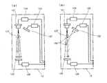
なお、図4は、上記実施の形態1から3に説明した試料分析装置に使用可能なエアロゾルセンサ12の構成の一例を示す構成図であり、図中(a)はエアロゾルが存在しない状態、(b)はエアロゾルが存在する状態を表している。
FIG. 4 is a block diagram showing an example of the configuration of the
上記エアロゾルセンサは、半導体レーザあるいは発光ダイオードなどの発光素子121を、発光素子駆動回路124にて発光させ、発光素子121の光軸上でエアロゾル検出領域127を挟んで発光素子121と対向する位置に透過光検出用光検出器123を、発光素子121の光軸外でエアロゾル検出領域127の方向に向けて散乱光検出用光検出器122を配置させた構成となっており、図の如くエアロゾルが存在しない状態では発光素子121から出射した光はエアロゾル検出領域127を透過して透過光検出用光検出器123に入射する。
In the aerosol sensor, a
一方、エアロゾルが存在する状態では、発光素子121から出射した光の一部は同様にエアロゾル検出領域127を透過して透過光検出用光検出器123に入射するが、一部はエアロゾル検出領域127内に存在するエアロゾル粒子150により反射/屈折/散乱して光路を曲げられ、散乱光検出用光検出器122に入射する。ここで、散乱光検出用光検出器122及び透過光検出用光検出器123からアンプ125、126を介して出力された信号の差分あるいは比率を取ることでエアロゾル検出領域127内にエアロゾルが存在するかどうかを判断することが可能となる。
On the other hand, in the state where the aerosol is present, part of the light emitted from the
ここで、透過光検出用光検出器123を用いず、散乱光検出用光検出器122の出力のみをモニターしてエアロゾルの存在を検知することも可能であるが、透過光と散乱光の両方をモニターして検出する方法の方が検出精度の面で優れている。試料の漏洩を検出するためのセンサとしては、上記の他に、液滴の付着を電気抵抗の変化から検出する方式のセンサなども使用可能であるが、センサに直接付着した液滴を検出する方式の場合、付着した試料が乾燥してセンサ表面に固着するため、長期の使用に伴ってセンサの検出感度が悪化する懸念があり、検出信頼性の面で推奨できない。
Here, it is possible to detect the presence of aerosol by monitoring only the output of the scattered
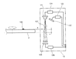
また、液体試料の漏洩によるエアロゾルの発生を確実に検知するためには、エアロゾルセンサ12を検体容器2の近傍に配置することが好ましい。特に、検体容器2が円盤形状を成し、試料分析時には検体容器2が円盤形状の中心を軸に回転するような構成の試料分析装置の場合には、図5に示すように、エアロゾルセンサ12を円盤形状の盤面の延長上にある、検体容器2の外周領域を検出するよう配置する。そして発光素子121からの光が円盤形状の盤面に垂直な方向に出射し、エアロゾル検出領域127が円盤形状を成した検体容器の全厚(図中Tの範囲)をカバーするように構成する。これにより、容器から漏出した検体100は回転する検体容器2の遠心力により前記検体容器2の外周方向(図中X方向)に移動しつつエアロゾルとなって飛散するため、検体の漏出を速やかに検出することが可能となり、安全性を高めることができる。
Further, in order to reliably detect the generation of aerosol due to leakage of the liquid sample, it is preferable to arrange the
更に、図5に示すように、発光素子121や散乱光検出用光検出器122、透過光検出用光検出器123を、円盤形状を成した検体容器2の全厚(図中Tの範囲)を避けて配置すれば、発光素子121、散乱光検出用光検出器122、透過光検出用光検出器が飛散したエアロゾルにより汚染されることを防止でき、長期にわたって検出信頼性を確保することができる。
Further, as shown in FIG. 5, the
本発明にかかる試料分析装置は、装置内部にエアロゾルを検知するエアロゾルセンサを備え、検体容器から液体試料が漏出したことを検知可能に構成することにより、検体容器から漏出しエアロゾルとなった検体が装置外に漏出する危険性を飛躍的に低減することが可能であり、着脱可能な検体容器に注入した液体試料の状態を分析するための試料分析装置等に有用であり、特に血液などの感染性試料を分析する際の試料漏洩防止に有効である。 The sample analyzer according to the present invention includes an aerosol sensor that detects aerosol in the apparatus, and is configured to detect that a liquid sample has leaked from the sample container. It is possible to drastically reduce the risk of leakage outside the device, and it is useful for sample analyzers for analyzing the state of a liquid sample injected into a detachable specimen container, especially infections such as blood This is effective in preventing sample leakage when analyzing a sex sample.
1 検体
2 検体容器
4 スピンドルモータ
5 光源手段
6 受光手段
7 ケース
9 排気ファン
10 フィルター部材
11 検体容器着脱扉
12 エアロゾルセンサ
13 制御回路
14 表示装置
15 ロック機構
100 容器より漏洩した検体
121 発光素子
122 散乱光検出用光検出器
123 透過光検出用光検出器
124 発光素子駆動回路
125、126 アンプ
127 エアロゾル検出領域
150 エアロゾル粒子
201 反応室
202 抗体
203 検体注入孔
DESCRIPTION OF SYMBOLS 1
Claims (9)
Priority Applications (1)
| Application Number | Priority Date | Filing Date | Title |
|---|---|---|---|
| JP2004108846A JP2005291987A (en) | 2004-04-01 | 2004-04-01 | Sample analyzer |
Applications Claiming Priority (1)
| Application Number | Priority Date | Filing Date | Title |
|---|---|---|---|
| JP2004108846A JP2005291987A (en) | 2004-04-01 | 2004-04-01 | Sample analyzer |
Publications (1)
| Publication Number | Publication Date |
|---|---|
| JP2005291987A true JP2005291987A (en) | 2005-10-20 |
Family
ID=35325071
Family Applications (1)
| Application Number | Title | Priority Date | Filing Date |
|---|---|---|---|
| JP2004108846A Pending JP2005291987A (en) | 2004-04-01 | 2004-04-01 | Sample analyzer |
Country Status (1)
| Country | Link |
|---|---|
| JP (1) | JP2005291987A (en) |
-
2004
- 2004-04-01 JP JP2004108846A patent/JP2005291987A/en active Pending
Similar Documents
| Publication | Publication Date | Title |
|---|---|---|
| AU2003285852B2 (en) | Point source biological agent detection system | |
| CA2442359C (en) | Optical biological measurement system using scraping means to collect the sample | |
| US6729196B2 (en) | Biological individual sampler | |
| US10309876B2 (en) | Cartridge for airborne substance sensing device, and airborne substance sensing device | |
| US6108096A (en) | Light absorption measurement apparatus and methods | |
| JP5860175B2 (en) | Airborne substance detection device and cartridge used therefor | |
| WO2019193878A1 (en) | Pathogen detection device and pathogen detection method | |
| CN101479609B (en) | Analysis panel and analysis device using same | |
| JP4859769B2 (en) | Analysis panel and analyzer using the same | |
| WO2019187910A1 (en) | Pathogen detection device and pathogen detection method | |
| KR20210132792A (en) | Personal Corona Antibody Diagnostic Kit Set | |
| JP7474950B2 (en) | Pathogen Detection Devices | |
| KR20220111362A (en) | Integrated system for identifying species of microbe in real-time | |
| JP2005291987A (en) | Sample analyzer | |
| US9482600B2 (en) | Sample collection unit, system and method for microbiological air analysis | |
| JP6779524B2 (en) | Containment performance inspection system | |
| EP0924508A2 (en) | Light absorption measurement apparatus and method | |
| KR20220111360A (en) | Apparatus for identifying species of microbe in real-time | |
| JP2006145359A (en) | Liquid sample analysis disc | |
| KR102616032B1 (en) | Apparatus and method for detecting virus using fluorescence separation | |
| JP2005037326A (en) | Analysis equipment | |
| JP4690742B2 (en) | Sample separation apparatus and flow cell | |
| JP2004177319A (en) | Liquid sample analyzer | |
| JP2003185666A (en) | Liquid sample measuring device | |
| JP2551622Y2 (en) | Cell analyzer |