JP2005291982A - Dynamic torque measuring device for rolling bearings - Google Patents
Dynamic torque measuring device for rolling bearings Download PDFInfo
- Publication number
- JP2005291982A JP2005291982A JP2004108737A JP2004108737A JP2005291982A JP 2005291982 A JP2005291982 A JP 2005291982A JP 2004108737 A JP2004108737 A JP 2004108737A JP 2004108737 A JP2004108737 A JP 2004108737A JP 2005291982 A JP2005291982 A JP 2005291982A
- Authority
- JP
- Japan
- Prior art keywords
- outer ring
- bearing
- link mechanism
- load
- rolling bearing
- Prior art date
- Legal status (The legal status is an assumption and is not a legal conclusion. Google has not performed a legal analysis and makes no representation as to the accuracy of the status listed.)
- Pending
Links
Images
Landscapes
- Force Measurement Appropriate To Specific Purposes (AREA)
- Testing Of Devices, Machine Parts, Or Other Structures Thereof (AREA)
- Rolling Contact Bearings (AREA)
Abstract
【課題】 ラジアルニードル軸受5に複数種類の荷重が作用した場合の、このラジアルニードル軸受5の動トルクや、ニードルのスキュー角等の特性を測定できる装置を実現する。
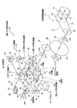
【解決手段】 外輪28を支持したリンク機構13を、ピボット軸受14により揺動自在に支持する。又、回転駆動装置12により内輪48を回転駆動する。この時、上記外輪28が連れ回りにより回転し、この回転は上記リンク機構13を構成する面板29に伝達される。又、第一の押圧装置41により、このリンク機構13を構成する支持棒30に、ラジアル荷重を負荷する。更に、第二、第三の押圧装置44、45によりこの面板29に、モーメント荷重を負荷する。これにより、上記外輪28に、ラジアル荷重及びモーメント荷重が負荷される。この状態で、この面板29に作用する力をロードセル15により検出して、上記ラジアルニードル軸受5の動トルクを測定する。これにより上記課題を解決できる。
【選択図】 図1PROBLEM TO BE SOLVED: To realize an apparatus capable of measuring characteristics such as a dynamic torque of a radial needle bearing 5 and a skew angle of a needle when a plurality of types of loads are applied to the radial needle bearing 5.
A link mechanism 13 that supports an outer ring 28 is supported by a pivot bearing 14 so as to be swingable. Further, the inner ring 48 is rotationally driven by the rotational driving device 12. At this time, the outer ring 28 is rotated along with the rotation, and this rotation is transmitted to the face plate 29 constituting the link mechanism 13. Further, a radial load is applied to the support rod 30 constituting the link mechanism 13 by the first pressing device 41. Further, a moment load is applied to the face plate 29 by the second and third pressing devices 44 and 45. As a result, a radial load and a moment load are applied to the outer ring 28. In this state, the force acting on the face plate 29 is detected by the load cell 15, and the dynamic torque of the radial needle bearing 5 is measured. Thereby, the said subject can be solved.
[Selection] Figure 1
Description
この発明は、ラジアルニードル軸受等の転がり軸受の動トルク測定装置の改良に関し、具体的には、この転がり軸受に複数種類の荷重を同時に負荷した状態で、この転がり軸受の動トルクや他の特性を測定する事が可能な装置を実現するものである。 The present invention relates to an improvement in a dynamic torque measuring device for a rolling bearing such as a radial needle bearing. Specifically, the present invention relates to the dynamic torque and other characteristics of the rolling bearing while a plurality of types of loads are simultaneously applied to the rolling bearing. An apparatus capable of measuring the above is realized.
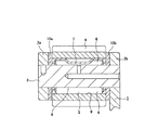
ラジアルニードル軸受により回転自在に支持された遊星歯車を備えた機械装置として、自動車用の自動変速装置が、広く知られている。この様な自動変速装置として従来から、複数の遊星歯車式変速機を組み合わせて成るもの、或はトロイダル型無段変速機と遊星歯車式変速機とを組み合わせて成るものが、広く知られている。又、この様な遊星歯車式変速機を組み込んだ自動変速装置の場合には、キャリアに対し遊星歯車を回転自在に支持する。この様に、キャリアに対し遊星歯車を回転自在に支持する構造に関しては、例えば特許文献1等、多数の文献に記載されて従来から周知である。図2は、上述の様にキャリアに対し遊星歯車を回転自在に支持する、遊星歯車の回転支持装置の1例を示している。 As a mechanical device including a planetary gear rotatably supported by a radial needle bearing, an automatic transmission for an automobile is widely known. Conventionally, such automatic transmissions are widely known in which a plurality of planetary gear type transmissions are combined, or in which a toroidal continuously variable transmission and a planetary gear type transmission are combined. . Further, in the case of an automatic transmission incorporating such a planetary gear type transmission, the planetary gear is rotatably supported with respect to the carrier. As described above, the structure for rotatably supporting the planetary gear with respect to the carrier is described in many documents such as Patent Document 1 and is well known. FIG. 2 shows an example of a planetary gear rotation support device that rotatably supports the planetary gear with respect to the carrier as described above.
この図2に示した構造では、キャリア1を構成する互いに平行な1対の支持板2a、2bの円周方向複数個所に、支持軸3の両端部を支持固定している。そして、この支持軸3の中間部周囲に遊星歯車4を、ラジアルニードル軸受5を介して、回転自在に支持している。このラジアルニードル軸受5は、複数本のニードル6、6を保持器7により転動自在に保持すると共に、上記支持軸3の中間部外周面を円筒状の内輪軌道8とし、上記遊星歯車4の内周面を円筒状の外輪軌道9として、上記各ニードル6、6の転動面を、これら内輪軌道8及び外輪軌道9に転がり接触させている。又、上記遊星歯車4の軸方向両端面と上記両支持板2a、2bの内側面との間には、それぞれフローティングワッシャ10a、10bを配置して、上記遊星歯車4の軸方向両端面と上記両支持板2a、2bの内側面との間の摩擦力の低減を図っている。
In the structure shown in FIG. 2, both end portions of the support shaft 3 are supported and fixed at a plurality of locations in the circumferential direction of a pair of
上述の様な構成を有する遊星歯車の回転支持装置は、ラジアル荷重は勿論、モーメント荷重が負荷された状態で使用される場合が多い。従って、この様な状態で使用される上記遊星歯車の回転支持装置に組み込むラジアルニードル軸受5には、複数の荷重が合成されて作用する。この様な合成荷重下で使用される上記遊星歯車の回転支持装置の場合、この回転支持装置に組み込むラジアルニードル軸受5を構成する各ニードル6、6の転動面に、フレーキング等の損傷を生じ易いと言う問題があった。
The planetary gear rotation support device having the above-described configuration is often used in a state where a moment load as well as a radial load is applied. Therefore, a plurality of loads are combined and act on the radial needle bearing 5 incorporated in the planetary gear rotation support device used in such a state. In the case of the rotation support device for the planetary gear used under such a composite load, damage such as flaking is caused on the rolling surfaces of the
上述の様な問題を解消する為には、フレーキングの損傷が生じる原因を調べる必要があるが、この為には、上記遊星歯車の回転支持装置に組み込まれた状態で作用する合成荷重を再現して、即ち、上記ラジアルニードル軸受5にラジアル方向とモーメント方向との合成荷重を負荷した状態で、このラジアルニードル軸受の動トルクや、上記各ニードル6、6の転動状態等の特性を測定する必要がある。転がり軸受の動トルクを測定する装置として、特許文献2〜4に記載された発明があるが、これら各特許文献に記載された発明は、測定される転がり軸受に積極的にモーメント荷重を負荷した状態で、この転がり軸受の動トルクを測定する構造とはなっていない。従って、上記各特許文献に記載された発明では、ラジアル荷重の他にモーメント荷重を負荷した状態で、転がり軸受の動トルクや他の特性を測定する事はできない。
In order to solve the above-mentioned problems, it is necessary to investigate the cause of the flaking damage, but for this purpose, the combined load acting in the state incorporated in the rotation support device of the planetary gear is reproduced. That is, with the radial needle bearing 5 subjected to a combined load of the radial direction and the moment direction, the dynamic torque of the radial needle bearing and the characteristics of the rolling state of the
本発明の転がり軸受の動トルク測定装置は、上述の様な事情に鑑み、転がり軸受に複数種類の荷重が同時に作用した場合の、この転がり軸受の動トルクや、転動体の転動状態等の特性を測定できる装置を実現すべく発明したものである。 In view of the above-described circumstances, the dynamic torque measuring device for a rolling bearing according to the present invention is such as the dynamic torque of the rolling bearing and the rolling state of the rolling element when a plurality of types of loads are simultaneously applied to the rolling bearing. It was invented to realize an apparatus capable of measuring characteristics.
本発明の転がり軸受の動トルク測定装置は、回転駆動装置と、リンク機構と、ピボット軸受と、荷重センサとを備える。
このうちの回転駆動装置は、転がり軸受を構成する内輪を回転駆動する為のものである。
又、上記リンク機構は、上記転がり軸受を構成する外輪の回転に伴って変形する様に、この外輪を直接若しくはハウジングを介して支持すると共に、この転がり軸受に複数種類の荷重を伝達自在としている。
又、上記ピボット軸受は、上記リンク機構を揺動自在に支持するものである。
又、上記荷重センサは、上記リンク機構の回転方向に作用する力を測定する為のものである。
The dynamic torque measuring device for a rolling bearing according to the present invention includes a rotation drive device, a link mechanism, a pivot bearing, and a load sensor.
Of these, the rotational drive device is for rotationally driving the inner ring constituting the rolling bearing.
The link mechanism supports the outer ring directly or via a housing so that the outer ring constituting the rolling bearing is deformed, and allows a plurality of types of loads to be transmitted to the rolling bearing. .
The pivot bearing supports the link mechanism in a swingable manner.
The load sensor is for measuring a force acting in the rotation direction of the link mechanism.
上述の様に構成する本発明の転がり軸受の動トルク測定装置の場合、複数方向(複数種類)の荷重を合成した合成荷重下に於ける転がり軸受の動トルクを測定できる。即ち、回転駆動装置により内輪を回転駆動した場合、ラジアルニードル軸受の動トルクにより、外輪も回転する傾向となる。この外輪を支持するリンク機構は、この外輪の回転に伴い変形する。又、このリンク機構は、ピボット軸受により揺動自在に支持されている。この為、上記外輪は、このリンク機構の変形及び揺動の範囲内で回転可能である。又、この回転は、このリンク機構に伝達される。従って、このリンク機構の回転方向に作用する力を測定する事により、上記転がり軸受の動トルクを検出できる。 In the rolling bearing dynamic torque measuring device of the present invention configured as described above, the dynamic torque of the rolling bearing can be measured under a combined load obtained by combining loads in a plurality of directions (plural types). That is, when the inner ring is rotationally driven by the rotational drive device, the outer ring also tends to rotate due to the dynamic torque of the radial needle bearing. The link mechanism that supports the outer ring is deformed as the outer ring rotates. The link mechanism is supported by a pivot bearing so as to be swingable. For this reason, the outer ring can rotate within a range of deformation and swing of the link mechanism. The rotation is transmitted to the link mechanism. Therefore, the dynamic torque of the rolling bearing can be detected by measuring the force acting in the rotational direction of the link mechanism.
又、上記外輪を支持するリンク機構に複数方向の荷重を負荷する事により、上記転がり軸受に合成荷重を負荷できる。即ち、上記リンク機構は上記ピボット軸受により支持されている為、このリンク機構が、このピボット軸受を中心に揺動可能である。従って、このリンク機構の揺動方向に荷重を負荷する事が可能である。又、このピボット軸受に所定方向の荷重を負荷すれば、このリンク機構全体に所定方向の荷重を負荷する事が可能である。本発明の場合、この様に、リンク機構に複数方向の荷重を負荷する事により、このリンク機構を介して上記転がり軸受に合成荷重を負荷できる。そして、この状態で、上述の様に、転がり軸受の動トルクを検出すれば、合成荷重下に於ける転がり軸受の動トルクが検出できる。
この結果、遊星歯車の回転支持装置の様に、合成荷重下で使用される回転支持装置に組み込む転がり軸受の性能向上に寄与できる。
Further, by applying a load in a plurality of directions to the link mechanism that supports the outer ring, a combined load can be applied to the rolling bearing. That is, since the link mechanism is supported by the pivot bearing, the link mechanism can swing around the pivot bearing. Therefore, it is possible to apply a load in the swing direction of the link mechanism. Further, if a load in a predetermined direction is applied to the pivot bearing, it is possible to apply a load in a predetermined direction to the entire link mechanism. In the case of the present invention, by applying loads in a plurality of directions to the link mechanism in this way, a combined load can be applied to the rolling bearing via the link mechanism. In this state, if the dynamic torque of the rolling bearing is detected as described above, the dynamic torque of the rolling bearing under the combined load can be detected.
As a result, like a planetary gear rotation support device, it can contribute to improving the performance of a rolling bearing incorporated in a rotation support device used under a combined load.
本発明を実施する為に好ましくは、請求項2に記載した様な構成とする。
即ち、リンク機構を、転がり軸受の中心軸に直交する仮想平面上に配置され、面板と、支持棒と、ヒンジ部と、1対の接続棒とにより構成されるものとする。
このうちの面板は、外輪若しくはハウジングの軸方向中央部外周面に、その中心部をこれら外輪若しくはハウジングが貫通する状態で固定する。
又、上記支持棒は、上記面板の周囲(例えば上方又は下方)に、この面板と平行に配置する。
又、上記ヒンジ部は、上記支持棒の両端部と上記面板の両端部とにそれぞれ設ける。
又、上記各接続棒は、上記各ヒンジ部を介して、上記支持棒と面板との両端部同士を接続する。
又、ピボット軸受により、上記支持棒の中央部を支持する。
又、このピボット軸受に上記転がり軸受の径方向(例えば上下方向)の荷重を負荷する事により、上記リンク機構を介して上記転がり軸受に、ラジアル荷重を負荷する。
又、上記面板のうちで、この転がり軸受の中心軸に関して対称位置に、この面板の表裏方向に関して互いに逆方向の力をそれぞれ付与する事により、この転がり軸受にモーメント荷重を負荷する。
この様に構成すれば、上記転がり軸受にラジアル方向及びモーメント方向の合成荷重を負荷した状態で、この転がり軸受の動トルクを測定できる。
In order to carry out the present invention, the structure as described in claim 2 is preferable.
That is, the link mechanism is disposed on a virtual plane orthogonal to the center axis of the rolling bearing and is constituted by a face plate, a support bar, a hinge part, and a pair of connecting bars.
Among these, the face plate is fixed to the outer peripheral surface of the axially central portion of the outer ring or the housing in a state where the outer ring or the housing penetrates the central portion.
The support rod is arranged around the face plate (for example, above or below) in parallel with the face plate.
The hinge portions are provided at both end portions of the support rod and both end portions of the face plate.
Moreover, each said connection rod connects the both ends of the said support rod and a face plate through each said hinge part.
The central portion of the support rod is supported by a pivot bearing.
Further, by applying a load in the radial direction (for example, the vertical direction) of the rolling bearing to the pivot bearing, a radial load is applied to the rolling bearing through the link mechanism.
In addition, a moment load is applied to the rolling bearing by applying forces in opposite directions with respect to the front and back directions of the face plate to symmetrical positions with respect to the center axis of the rolling bearing.
If comprised in this way, the dynamic torque of this rolling bearing can be measured in the state which applied the combined load of the radial direction and the moment direction to the said rolling bearing.
又、より好ましくは、請求項3に記載した様に、上記リンク機構を構成する各ヒンジ部に、被測定物とは別の、支承用転がり軸受を組み込む。
この様に構成すれば、リンク機構が変形する事に対する摩擦損失を極めて小さくでき、上記被測定物である転がり軸受の動トルクを、より正確に測定できる。
更に好ましくは、請求項4に記載した様に、上記外輪の両端面に対向させて、この外輪に作用するスラスト方向の力を測定する為の荷重センサを設置する。
この様に構成すれば、転がり軸受の運転中に生じるスラスト力が測定可能である。即ち、本発明の場合、上記外輪を支持するリンク機構がピボット軸受により支持されている為、上記転がり軸受に生じるスラスト力によりこの外輪がスラスト方向に変位可能である。従って、この外輪がスラスト方向に移動する力を測定する事により、上記転がり軸受に生じるスラスト力を測定できる。
More preferably, as described in claim 3, a rolling bearing for support, which is different from the object to be measured, is incorporated in each hinge part constituting the link mechanism.
If comprised in this way, the friction loss with respect to a deformation | transformation of a link mechanism can be made very small, and the dynamic torque of the rolling bearing which is the said to-be-measured object can be measured more correctly.
More preferably, as described in
If comprised in this way, the thrust force which arises during the driving | operation of a rolling bearing can be measured. That is, in the case of the present invention, since the link mechanism that supports the outer ring is supported by the pivot bearing, the outer ring can be displaced in the thrust direction by the thrust force generated in the rolling bearing. Therefore, the thrust force generated in the rolling bearing can be measured by measuring the force with which the outer ring moves in the thrust direction.
又、請求項5に記載した様に、上記被測定物である転がり軸受がラジアルニードル軸受である場合には、このラジアルニードル軸受を構成する外輪の外周面複数個所で少なくとも軸方向に離隔した位置に、このラジアルニードル軸受を構成する各ニードルの通過を検知する為のセンサを、それぞれ設置する事が好ましい。
この様に構成すれば、上記軸方向に離隔した位置でそれぞれ検知した各ニードルの通過時間のずれから、合成荷重下に於ける上記各ニードルのスキュー角を求める事ができる。又、これら各ニードルの公転速度も検出可能である。
Further, when the rolling bearing as the object to be measured is a radial needle bearing as described in
If comprised in this way, the skew angle of each said needle under a synthetic | combination load can be calculated | required from the shift | offset | difference of the passing time of each needle | hook detected in the position separated in the said axial direction. Further, the revolution speed of each needle can also be detected.
図1は、本発明の実施例を示している。本実施例の動トルク測定装置11は、前述の遊星歯車の回転支持装置の運転状態に近い状態を再現し、この状態で、この回転支持装置に組み込むラジアルニードル軸受5等の転がり軸受の動トルク等の各種特性を測定するものである。この為に、上記動トルク測定装置11は、回転駆動装置12と、リンク機構13と、ピボット軸受14と、請求項1に記載した荷重センサであるロードセル15とを備える。このうちの回転駆動装置12は、上記動トルク測定装置11により動トルクを測定する対象である、上記ラジアルニードル軸受5の内輪軌道8(図2参照。尚、図2では、支持軸3の外周面に内輪軌道8を形成している。従って、図2の構造では、支持軸3が内輪に相当する。)を形成した内輪48を回転駆動する為のものである。又、上記内輪48を回転駆動する為に、上記回転駆動装置12は、電動モータ16と、ベルト伝達部17と、歯車伝達部18とを備える。そして、この電動モータ16の動力をこれらベルト伝達部17と歯車伝達部18とを介して、上記内輪48に伝達自在としている。
FIG. 1 shows an embodiment of the present invention. The dynamic
上記ベルト伝達部17は、駆動プーリ20と、従動プーリ22と、これら駆動プーリ20と従動プーリ22との間に掛け渡したベルト21とから成り、上記歯車伝達部18は、大歯車25と小歯車26とから成る。そして、上記電動モータ16の動力は、次の様に上記内輪48に伝達される。即ち、上記電動モータ16の回転駆動軸19を回転駆動する事により、この回転駆動軸19の先端(図1の左上)部に固定した上記駆動プーリ20を回転させる。この駆動プーリ20の回転は、上記ベルト21を介して上記従動プーリ22に伝達される。
The
又、上記従動プーリ22をその基端(図1の右下)部に固定した中間軸23は、両端部を転がり軸受や滑り軸受等の軸受24a、24aにより回転自在に支持されており、中間部に上記大歯車25を固定している。又、この大歯車25の周囲に、この大歯車25と噛合する上記小歯車26を配置している。この小歯車26は、その中間部に上記内輪48を外嵌固定してこの内輪48と共に回転する、主軸27の中間部基端寄り(図1の右下寄り)部分に固定されている。従って、上記従動プーリ22に伝達された回転駆動力は、上記大歯車25と小歯車26とを介して、上記主軸27に伝達される。この様に、本実施例の場合、上記電動モータ16の回転駆動力を、上記プーリ伝達部17と上記歯車伝達部18とを介する事により増速して、上記主軸27に外嵌した上記内輪48に伝達している。尚、この主軸27は、上記小歯車26と上記内輪48との間と、一端部(図の左上部)とが、それぞれ転がり軸受或は滑り軸受等の軸受24b、24bにより回転自在に支持されている。
The
又、本実施例の場合、前記ラジアルニードル軸受5の外輪軌道9(図2参照。尚、図2では、遊星歯車4の内周面に外輪軌道9を形成している。従って、図2の構造では、遊星歯車4が外輪に相当する。)を外輪28の内周面に形成している。そして、上記内輪48の外周面に形成した上記内輪軌道8と、この外輪軌道9との間に複数のニードル6、6(図2参照)を、転動自在に設けている。従って、上記外輪28は、上記内輪48に対して回転自在である。又、この外輪28は、前記リンク機構13により支持されている。尚、この外輪28にハウジングを外嵌する場合もある。この場合、このハウジングをこのリンク機構13により支持する。
In the case of this embodiment, the
上記リンク機構13は、上記ラジアルニードル軸受5の中心軸に直交する仮想平面上に配置されており、面板29と、支持棒30と、4個所のヒンジ部35、35と、1対の接続棒31、31とから構成される。このうちの面板29は、中心部に通孔32を設けた主部33と、この主部33の両側に設けた腕部34、34とから成る。そして、この通孔32に上記外輪28を貫通する状態で内嵌固定して、上記面板29とこの外輪28とを不離に結合している。又、この面板29が、この外輪28の軸方向中央部に位置する様に固定されている。尚、この面板29は、金属製或は合成樹脂製とし、上記腕部34、34が湾曲したり、後述する様にこの面板29に作用する荷重により変形しない程度の剛性を確保する。又、本実施例の場合、上記面板29を図示の様な形状とする事により、余分な部分(例えば、腕部34、34の下部)を除肉して軽量化を図っている。これにより、上記面板29の慣性質量を低減している。
The link mechanism 13 is disposed on a virtual plane orthogonal to the central axis of the
又、上記支持棒30は、上記面板29の上側に、この面板29と平行に配置されている。この支持棒30も金属製等とする事により、この支持棒30に作用する荷重により変形しない程度の剛性を確保している。又、この支持棒30の両端部と、上記面板29の両端部に設けた腕部34、34とに、それぞれ上記ヒンジ部35、35を設けている。又、上記支持棒30の両端部と腕部34、34の先端部とを、これら各ヒンジ部35、35を介して、上記接続棒31、31により接続している。従って、これら支持棒30及び腕部34、34とこれら各接続棒31、31との連結部には、それぞれヒンジ部35、35が存在し、各部材29、30、31が、これら各ヒンジ部35、35を支点として互いに揺動変位自在となる。又、これら各ヒンジ部35、35には、転がり軸受36、36を組み込んで、これら各ヒンジ部35、35が揺動変位する事に対する抵抗を低減している。本実施例の場合、上記各部材29、30、31を、上述した様に構成する事により、矩形若しくは平行四辺形の、リンク機構13を形成している。
Further, the support rod 30 is disposed on the upper side of the
又、本実施例の場合、このリンク機構13は、その全体が、前記ピボット軸受14により揺動自在に支持されている。即ち、このリンク機構13を構成する上記支持棒30の中央下部に、上記ピボット軸受14を構成する雌部を形成した部材を固設している。尚、この支持棒30の中央下部に直接、この雌部を形成しても良い。又、上記ピボット軸受14を構成する雄部は、後述する、上記リンク機構13に荷重を負荷する為のラジアル荷重負荷装置38を構成する揺動腕部39の中間部に、その中心軸αをほぼ鉛直方向に位置させて、上方に向けて固設している。そして、この揺動腕部39に設けた上記雄部と上記支持棒30に設けた上記雌部とを係合させている。従って、上記リンク機構13は、上記ピボット軸受14を中心に揺動可能な状態となる。具体的には、このリンク機構13を構成する支持棒30が、上記ピボット軸受14を中心に揺動可能な状態となり、この支持棒30の揺動に伴い、上記リンク機構13が変形する。尚、上記ピボット軸受14は、後述する、このピボット軸受14を介して上記リンク機構13に負荷される荷重に、十分に耐えられる強度及び剛性を確保する。
In this embodiment, the entire link mechanism 13 is supported by the pivot bearing 14 so as to be swingable. That is, a member in which a female portion constituting the pivot bearing 14 is formed is fixed to the lower center portion of the support rod 30 constituting the link mechanism 13. In addition, you may form this female part directly in the center lower part of this support bar 30. FIG. The male part constituting the pivot bearing 14 has a central axis α at an intermediate part of a
尚、上記ピボット軸受14は、ピボット玉軸受としても良い。又、このピボット軸受14を配置する方向は、上述した場合と上下反対としても良い。即ち、上記雄部を上記支持棒30の中央部に下方に向けて固設し、上記雌部を上記揺動腕部39の中間部の上部に設けても良い。本発明者が、実際に本実施例の装置を組んで、上記ピボット軸受14の配置する方向を変えて実施した結果、上記リンク機構13の揺動量が小さかった為、このピボット軸受14をどちらの方向に配置しても、このリンク機構13の揺動に支障はなかった。
The
又、上記ラジアル荷重負荷装置38は、前記ラジアルニードル軸受5にラジアル荷重を負荷する為のもので、上記揺動腕部39と、この揺動腕部39の基端部(図の左上部)を支持する揺動支持部40と、この揺動腕部39の先端部(図の右下部)に上方に向く力を付与する為の第一の押圧装置41とから構成される。このうちの揺動支持部40は、固定の部分に設置されており、上面を、互いに逆方向に傾斜した傾斜面42、42としている。即ち、これら各傾斜面42、42は、上記揺動腕部39の配設方向に直交する様に配置され、下方に向かう程互いに近付く方向に傾斜している。そして、上記各傾斜面42、42の下端縁同士を突き合わせている。又、これら各傾斜面42、42の突き合わせた部分(最底部)に、上記揺動腕部39の基端部を下方に折り曲げた折り曲げ部43の下端部を突き当てている。
The radial
又、上記折り曲げ部43の下端部はナイフエッジとしており、このナイフエッジの先端を、上記各傾斜面42、42同士を突き合わせた部分に当接させている。そして、上記折り曲げ部43の下端部のナイフエッジと上記揺動支持部40とにより、ナイフエッジ軸受を構成している。従って、上記揺動腕部39は、上記ナイフエッジと上記各傾斜面42、42を突き合わせた部分との当接部を支点として、揺動可能である。尚、上記ナイフエッジを支承する上記揺動支持部40及びこのナイフエッジに就いても、負荷荷重に十分耐えられる様に、材料や形状等を設計的に定める。又、上記揺動腕部39の下端部を揺動自在に支承できれば、上述したナイフエッジ軸受以外に、例えば、ピボット軸受を採用しても良い。但し、本実施例の様に、ナイフエッジ軸受を採用すれば、このナイフエッジ軸受に荷重が負荷される事により上記揺動腕部39の位置が安定し、この揺動腕部39が所望の方向以外に揺動する事を防止できる。
The lower end of the
又、上記第一の押圧装置41は、エアシリンダにより構成して、上記揺動腕部39の先端部に上方向の荷重を負荷するもので、シリンダを固定の部分に設置し、このシリンダによりロッドを、上下方向の移動自在としている。又、このロッドの先端部を、上記揺動腕部39の先端部に係合させている。そして、上記シリンダ内に圧縮空気を送り込む事により上記ロッドを上昇させて、この揺動腕部39の先端部に上方向の荷重を負荷自在としている。尚、上記第一の押圧装置41は、エアシリンダ以外に、オイルによる圧力を利用する等、その他の手段を採用しても良い。即ち、上記揺動腕部39に上向きの力を付与できる構造であれば良い。
The first pressing device 41 is constituted by an air cylinder and applies an upward load to the tip of the
上述の様に構成する本実施例の場合、上記第一の押圧装置41により上記揺動腕部39の先端部を上昇させる事により、この揺動腕部39を上記ナイフエッジ軸受を支点として上方向に揺動させる。この結果、前記ピボット軸受14を介して上記リンク機構13に、上向の荷重を負荷できる。尚、本実施例の場合、上記支持棒30を上記揺動腕部39に対してピボット軸受14により支承している為、この揺動腕部39が上向に揺動しても、この支承している部分がずれる事は殆どない。即ち、この揺動腕部39が上方向に揺動した場合に、この揺動腕部39に固定された、上記ピボット軸受14を構成する雄部の中心軸αが鉛直方向に対してずれる傾向となっても、この雄部が上記支持棒30に固定された雌部からずれる事は殆どない。この為、この揺動腕部39から上記支持棒30に対して確実に荷重を負荷できる。
In the case of the present embodiment configured as described above, the first pressing device 41 raises the tip of the
又、上述の様に、リンク機構13に上方向の荷重を負荷する事により、前記ラジアルニードル軸受5を構成する外輪28に対してラジアル方向の荷重を負荷できる。即ち、前述の様に、この外輪28は、上記リンク機構13により支持されている為、このリンク機構13に荷重を負荷すれば、この外輪28にも荷重が負荷される。又、このリンク機構13は、このラジアルニードル軸受5の中心軸に直交する仮想平面上に存在する為、このリンク機構13に上方向の荷重を負荷すれば、上記外輪28にも上方向のラジアル荷重が負荷される。そして、上記第一の押圧装置41のシリンダ内に送り込む空気圧を変えたり、揺動腕部39の軸方向に関して、この揺動腕部39により上記支持棒30に荷重を負荷する位置を変える等により、上記ラジアル荷重の大きさを調整できる。又、上述した構造では、リンク機構13に上方向に向く荷重を負荷する事により、外輪28に上方向のラジアル荷重を負荷する構造としているが、支持棒30及びピボット軸受14を面板29の下側に配置して、リンク機構13に下方向に向く荷重を負荷する事により、上記外輪28の下方向のラジアル荷重を負荷する様にしても良い。
Further, as described above, by applying an upward load to the link mechanism 13, it is possible to apply a radial load to the
又、本実施例の場合、上記ラジアルニードル軸受5に対してモーメント荷重を負荷する構造としている。即ち、上記リンク機構13を構成する面板29のうちで、上記ラジアルニードル軸受5の中心軸に関して対称位置に、この面板29の表裏方向に関して互いに逆方向の力を付与する。この為に、この面板29の主部33の一部で、上記ラジアルニードル軸受5を貫通させる通孔32の両側に、エアシリンダ等の第二、第三の押圧装置44、45を配置する。これら各押圧装置44、45は、上述した第一の押圧装置41と同様に、空気圧等によりロッドを押し引き自在としており、このロッドの先端面を上記面板29の所定位置に突き当て自在としている。
In this embodiment, a moment load is applied to the
即ち、上記各押圧装置44、45は、上記面板29の表裏方向に関して、互いに逆側に設けている。具体的には、第二の押圧装置44は、この面板29の一方の面側(図の手前側)に、第三の押圧装置45は、この面板29の他方の面側(図の奥側)にそれぞれ設けている。又、これら各押圧装置44、45は、上記ラジアルニードル軸受5の中心軸に対して対称に配置されている。従って、この中心軸からそれぞれの設置位置までの距離は同じである。又、上記各押圧装置44、45の上下方向の位置は、上記ラジアルニードル軸受5の中心軸と直交し上記面板29と平行な仮想線βで示す様に、このラジアルニードル軸受5の中心軸と同じ高さ位置としている。そして、この様に配置された各押圧装置44、45の各ロッドを、上記面板29のそれぞれ対向する部分に当接させる。
That is, the
上記ラジアルニードル軸受5に前記モーメント荷重を負荷する為には、上述の様に配置された各押圧装置44、45に圧縮空気を送り込んでロッドを押し出す事により、上記面板29のそれぞれ当接している部分を、図の矢印イ方向と矢印ロ方向とにそれぞれ押圧する。この結果、上記面板29に対して矢印ハ方向にモーメント荷重を負荷できる。本実施例の場合、この面板29が上記揺動腕部39に対してピボット軸受14により支持されている為、この面板29が、このピボット軸受14を中心に揺動自在である。従って、この面板29に対して上述した様なモーメント荷重を負荷した場合、この面板29に固定される前記外輪28にもモーメント荷重が負荷され、この外輪28が前記内輪48に対して傾斜する傾向となる。尚、本実施例の場合、上記第二、第三の押圧装置44、45の押圧力若しくはラジアルニードル軸受5の中心軸からの距離を変える事により、この外輪28に負荷するモーメント荷重を調節可能である。そして、このモーメント荷重を調節する事により、この外輪28の上記内輪48に対する傾斜角度を変える事ができる。
In order to apply the moment load to the
又、本実施例の場合、上記面板29の一方(図の手前側)の腕部34の下側に、前記ロードセル15を設置している。このロードセル15は、この一方の腕部34に作用する力を測定する為のものである。そして、このロードセル15でこの腕部34に作用する力を測定する事により、上記ラジアルニードル軸受5に発生する動トルクが測定可能である。即ち、前述した回転駆動装置12により、このラジアルニードル軸受5を構成する内輪48を回転させた場合に、この内輪48の周囲に配置した上記外輪28も連れ回りにより回転する傾向となる。即ち、前記各ニードル6、6の転動面と、前記内輪、外輪両軌道8、9との摩擦により、上記内輪48の回転に伴い上記外輪28に連れ回ろうとする力が作用して、この外輪28が回転する傾向となる。この外輪28に作用する力がラジアルニードル軸受5の動トルクに相当する。そして、この外輪28の連れ回りによる回転に伴い、この外輪28に固定された上記面板29が、上記ラジアルニードル軸受5の内輪48を中心に揺動する傾向になる。本実施例の場合、この面板29は、前述した様に、リンク機構13の一部を構成する為、このリンク機構13が変形する事により、この面板29の揺動を許容する。
In the case of this embodiment, the load cell 15 is installed below the
具体的には、上記外輪28が、図の矢印ニ方向に回転する傾向となった場合、上記リンク機構13が変形する事により、上記一方の腕部34が下側に、他方の腕部34が上側に、それぞれ変位する。本実施例では、このリンク機構13を構成する支持棒30がピボット軸受14により支持されている為、この支持棒30がこのピボット軸受14を支点として回転方向に揺動自在である。又、この支持棒30及び上記各腕部34、34と、前記接続棒31、31とを連結する前記各ヒンジ部35、35に、転がり軸受36、36を組み込んでいる為、このリンク機構13は滑らかに(摩擦損失が少なく)変形する。従って、上記外輪28に作用するトルクがほぼ損失なく、上記一方の腕部34に伝達される。
Specifically, when the
上述の様に、外輪28と共に上記面板29が回転方向に揺動する事により、この面板29の一方の腕部34に、この外輪28に作用するトルクが伝達される。従って、この一方の腕部34に伝達される力を上記ロードセル15で検出する事により、上記外輪28に作用するトルクを検出できる。尚、上記ロードセル15を設置する場所は、上記面板29に作用する回転方向の力を検出できれば、図示の例以外の場所であっても良い。
As described above, the
又、本実施例の場合、上記外輪28の軸方向両端面に対向させて、上記ラジアルニードル軸受5に生じるスラスト力を測定する為の、請求項4に記載した荷重センサである、スラスト力用ロードセル46、46を設置している。即ち、上記ラジアルニードル軸受5の運転中に、スラスト方向の力が発生する場合がある。本実施例の場合、上記ラジアルニードル軸受5を構成する内輪48は、前述の様に、主軸27に外嵌されており、この主軸27は軸受24b、24bに固定されている。この為、この内輪48はスラスト方向には変位不能である。又、本実施例の場合、上記外輪28は、前述の様に、リンク機構13により支持されており、このリンク機構13は、ピボット軸受14により支持されている。この為、このリンク機構13及び上記外輪28が、このピボット軸受14を中心にスラスト方向に揺動可能である。この為、上述の様に、ラジアルニードル軸受5にスラスト方向の力が発生した場合、この力によって上記外輪28がスラスト方向に変位する。従って、この外輪28の両端面にスラスト力用ロードセル46、46を設置して、この外輪28がスラスト方向に変位しようとする力を測定する事により、上記ラジアルニードル軸受5の運転中に生じるスラスト力を検出できる。
Further, in the case of this embodiment, the load sensor according to
更に、本実施例の場合、上記ラジアルニードル軸受5を構成する外輪28の外周面の軸方向2個所位置に、請求項5に記載した各ニードル6、6の通過を検知する為のセンサである、ギャップセンサ47、47を設置している。即ち、上記ラジアルニードル軸受5を構成する外輪28の外周面で、軸方向に離れた2個所位置に、上記ギャップセンサ47、47を、このラジアルニードル軸受5の中心軸と直交する方向に配置している。図示の例では、上記面板29を挟んだ軸方向両側にそれぞれギャップセンサ47、47を設置している。そして、この軸方向2個所位置での、上記各ニードル6、6の通過をそれぞれ検知する。この様に構成する本実施例の場合、上記各ギャップセンサ47、47がそれぞれ検知するこれら各ニードル6、6の通過時間のずれを求める事により、これら各ニードル6、6のスキュー角を検出できる。又、これら各ニードル6、6の通過速度から、これら各ニードル6、6の公転速度も検出できる。
Furthermore, in the case of the present embodiment, the sensor is for detecting the passage of the
尚、本実施例の場合、上記各ギャップセンサ47、47を2個所に設置した場合に就いて示したが、更に多数のギャップセンサを設置しても良い。例えば、外輪28の円周方向の3個所で、ラジアル荷重の負荷圏、非負荷圏、これらの中間の位置にギャップセンサをそれぞれ設けても良い。この場合にも、各円周方向の位置毎に、ギャップセンサを2個ずつ、軸方向に離隔して設置する。この様に構成すれば、それぞれの位置での各ニードル6、6のスキュー角を検出できる為、ラジアルニードル軸受5の運転時に於ける各ニードル6、6の挙動を詳細に知る事ができる。
In this embodiment, the
上述の様に構成される本実施例の構造により、上記ラジアルニードル軸受5の動トルクを測定する場合には、先ず、電動モータ16により主軸27を回転駆動する。この電動モータ16の動力は、ベルト伝達部17と歯車伝達部18とを介して上記主軸27に伝達されて、この主軸27に外嵌された、ラジアルニードル軸受5を構成する内輪48が回転する。次に、この様にラジアルニードル軸受5を運転した状態で、このラジアルニードル軸受5に、リンク機構13を介してラジアル方向及びモーメント方向の荷重を負荷する。これにより、実際の運転状態に近い状態を再現できる。そして、この状態で、上記ラジアルニードル軸受5の動トルクを、上記リンク機構13を介して測定する。又、このラジアルニードル軸受5に生じるスラスト力や、各ニードル6、6のスキュー角、公転速度も検出する。
In the case of measuring the dynamic torque of the
上述した様に構成される、本実施例の動トルク測定装置11の場合、リンク機構13を介してラジアルニードル軸受5にラジアル方向とモーメント方向の荷重を負荷し、このリンク機構13を介してこのラジアルニードル軸受5の動トルクを検出する。この為、このラジアルニードル軸受5の動トルクを、実際の運転状態に近い状態で検出できる。又、本実施例の場合、このラジアルニードル軸受5の動トルクに加えて、このラジアルニードル軸受5の運転時に生じるスラスト力や、このラジアルニードル軸受5の各ニードル6、6のスキュー角及び公転速度も検出できる。この様に、実際の運転状況に近い状態で、上記ラジアルニードル軸受5の動トルクや各ニードル6、6のスキュー角等の特性を調べる事ができれば、前述した遊星歯車の回転支持装置の様に、合成荷重下で使用される回転支持装置に組み込むラジアルニードル軸受に生じるフレーキング発生等の問題の解決に寄与できる。そして、このラジアルニードル軸受の性能向上に寄与できる。
In the case of the dynamic
又、本実施例の場合、ラジアル荷重とモーメント荷重を同時に負荷した状態で、各種測定を行なう場合に就いて説明したが、どちらか一方の荷重のみを負荷した状態で、上述した各種測定を行なっても良い。この様に本実施例の場合、種々の条件で各種測定が可能な為、それぞれの条件毎に装置を製造する必要がなくなる。この結果、試験装置の製造コストの低減を図れる。 Further, in the case of the present embodiment, the case where various measurements are performed with a radial load and a moment load applied simultaneously has been described. However, the above-described various measurements are performed with only one of the loads being applied. May be. In this way, in the present embodiment, various measurements can be performed under various conditions, so that it is not necessary to manufacture a device for each condition. As a result, the manufacturing cost of the test apparatus can be reduced.
1 キャリア
2a、2b 支持板
3 支持軸
4 遊星歯車
5 ラジアルニードル軸受
6 ニードル
7 保持器
8 内輪軌道
9 外輪軌道
10a、10b フローティングワッシャ
11 動トルク測定装置
12 回転駆動装置
13 リンク機構
14 ピボット軸受
15 ロードセル
16 電動モータ
17 ベルト伝達部
18 歯車伝達部
19 回転駆動軸
20 駆動プーリ
21 ベルト
22 従動プーリ
23 中間軸
24a、24b 軸受
25 大歯車
26 小歯車
27 主軸
28 外輪
29 面板
30 支持棒
31 接続棒
32 通孔
33 主部
34 腕部
35 ヒンジ部
36 転がり軸受
38 ラジアル荷重負荷装置
39 揺動腕部
40 揺動支持部
41 第一の押圧装置
42 傾斜面
43 折り曲げ部
44 第二の押圧装置
45 第三の押圧装置
46 スラスト力用ロードセル
47 ギャップセンサ
48 内輪
DESCRIPTION OF SYMBOLS 1
Claims (5)
ピボット軸受が、上記支持棒の中央部を支持しており、
このピボット軸受に上記転がり軸受の径方向の荷重を負荷する事により、上記リンク機構を介して上記転がり軸受にラジアル荷重を負荷し、
上記面板のうちでこの転がり軸受の中心軸に関して対称位置に、この面板の表裏方向に関して互いに逆方向の力をそれぞれ付与する事により、この転がり軸受にモーメント荷重を負荷する、請求項1に記載した転がり軸受の動トルク測定装置。 A link mechanism is disposed on a virtual plane orthogonal to the center axis of the rolling bearing, and a face plate fixed to the outer peripheral surface of the outer ring or housing in the axial direction central portion thereof in a state in which the outer ring or the housing penetrates the center portion; Around the face plate, support rods arranged in parallel to the face plate, hinge portions provided at both ends of the face plate and both end portions of the support rod, and the support rods via the hinge portions, It is composed of a pair of connecting rods that connect both ends of the face plate,
A pivot bearing supports the central portion of the support rod,
By applying a radial load of the rolling bearing to the pivot bearing, a radial load is applied to the rolling bearing via the link mechanism,
The moment load is applied to the rolling bearing by applying forces in opposite directions with respect to the front and back directions of the face plate at symmetrical positions with respect to the center axis of the rolling bearing among the face plates. A dynamic torque measuring device for rolling bearings.
Priority Applications (1)
| Application Number | Priority Date | Filing Date | Title |
|---|---|---|---|
| JP2004108737A JP2005291982A (en) | 2004-04-01 | 2004-04-01 | Dynamic torque measuring device for rolling bearings |
Applications Claiming Priority (1)
| Application Number | Priority Date | Filing Date | Title |
|---|---|---|---|
| JP2004108737A JP2005291982A (en) | 2004-04-01 | 2004-04-01 | Dynamic torque measuring device for rolling bearings |
Publications (1)
| Publication Number | Publication Date |
|---|---|
| JP2005291982A true JP2005291982A (en) | 2005-10-20 |
Family
ID=35325066
Family Applications (1)
| Application Number | Title | Priority Date | Filing Date |
|---|---|---|---|
| JP2004108737A Pending JP2005291982A (en) | 2004-04-01 | 2004-04-01 | Dynamic torque measuring device for rolling bearings |
Country Status (1)
| Country | Link |
|---|---|
| JP (1) | JP2005291982A (en) |
Cited By (5)
| Publication number | Priority date | Publication date | Assignee | Title |
|---|---|---|---|---|
| KR101447573B1 (en) * | 2013-04-16 | 2014-10-07 | 설동규 | Torque Measuring Device for Tapered Roller Bearings |
| CN104089776A (en) * | 2014-07-23 | 2014-10-08 | 安徽工程大学 | Testing device for measuring rolling bearing force and deformation relation |
| CN109406125A (en) * | 2018-11-26 | 2019-03-01 | 吉林大学 | Portable main shaft full working scope load and device for detecting performance |
| CN114252264A (en) * | 2022-01-06 | 2022-03-29 | 北京航空航天大学 | A planetary row needle roller bearing test device and method |
| CN120761030A (en) * | 2025-09-04 | 2025-10-10 | 山东丰源汽车科技有限公司 | A dynamic torque detection device for a transmission shaft |
-
2004
- 2004-04-01 JP JP2004108737A patent/JP2005291982A/en active Pending
Cited By (7)
| Publication number | Priority date | Publication date | Assignee | Title |
|---|---|---|---|---|
| KR101447573B1 (en) * | 2013-04-16 | 2014-10-07 | 설동규 | Torque Measuring Device for Tapered Roller Bearings |
| CN104089776A (en) * | 2014-07-23 | 2014-10-08 | 安徽工程大学 | Testing device for measuring rolling bearing force and deformation relation |
| CN109406125A (en) * | 2018-11-26 | 2019-03-01 | 吉林大学 | Portable main shaft full working scope load and device for detecting performance |
| CN109406125B (en) * | 2018-11-26 | 2024-05-10 | 吉林大学 | Portable spindle full-working-condition loading and performance detecting device |
| CN114252264A (en) * | 2022-01-06 | 2022-03-29 | 北京航空航天大学 | A planetary row needle roller bearing test device and method |
| CN114252264B (en) * | 2022-01-06 | 2022-08-12 | 北京航空航天大学 | A planetary row needle roller bearing test device and method |
| CN120761030A (en) * | 2025-09-04 | 2025-10-10 | 山东丰源汽车科技有限公司 | A dynamic torque detection device for a transmission shaft |
Similar Documents
| Publication | Publication Date | Title |
|---|---|---|
| EP2767728A1 (en) | Continuously variable transmission | |
| CN111504831B (en) | Bearing steel ball friction and wear performance test bench and test method | |
| CN103586982B (en) | Transmission device of mixer truck | |
| JP2005291982A (en) | Dynamic torque measuring device for rolling bearings | |
| US20080118344A1 (en) | Helical Gear Supporting Structure, Speed Increaser for Wind Power Generator, and Vertical Shaft Supporting Structure | |
| US6328669B1 (en) | Toroidal type continuously variable transmission | |
| CN115420504A (en) | Aerogenerator base bearing moment test system that topples | |
| CN114544176A (en) | Bearing testing device | |
| US6408518B1 (en) | Method and apparatus for assembling balls forming ball spline of toroidal-type continuously variable transmission | |
| JP2006177447A (en) | Double-row rolling bearing | |
| JP2006047180A (en) | Roller bearing cage wear test method and cage wear test apparatus | |
| JP2975903B2 (en) | Swivel bearing | |
| JP2000162092A (en) | Dynamic torque measuring device for rolling bearings | |
| US6449868B1 (en) | Measuring apparatus for a power roller unit for a toroidal type continuous variable speed transmission | |
| US6945904B2 (en) | Toroidal-type continuously variable transmission | |
| JP5318514B2 (en) | Torque measuring device | |
| JP3864646B2 (en) | Reference length measuring device for input side disk unit for toroidal type continuously variable transmission | |
| JP2000205362A (en) | Toroidal type continuously variable transmission | |
| JP2001124165A5 (en) | ||
| CN219906379U (en) | Tension control device | |
| JPH0216861B2 (en) | ||
| JP2001050360A (en) | Toroidal type continuously variable transmission | |
| JP2001304366A (en) | Toroidal type continuously variable transmission | |
| JPH0474660B2 (en) | ||
| US12411050B1 (en) | Radial load measuring apparatus |