JP2005291973A - Efficiency measuring method of speed change gear, and device used therefor - Google Patents
Efficiency measuring method of speed change gear, and device used therefor Download PDFInfo
- Publication number
- JP2005291973A JP2005291973A JP2004108404A JP2004108404A JP2005291973A JP 2005291973 A JP2005291973 A JP 2005291973A JP 2004108404 A JP2004108404 A JP 2004108404A JP 2004108404 A JP2004108404 A JP 2004108404A JP 2005291973 A JP2005291973 A JP 2005291973A
- Authority
- JP
- Japan
- Prior art keywords
- load
- efficiency
- speed change
- transmission
- change gear
- Prior art date
- Legal status (The legal status is an assumption and is not a legal conclusion. Google has not performed a legal analysis and makes no representation as to the accuracy of the status listed.)
- Pending
Links
- 238000000034 method Methods 0.000 title claims abstract description 9
- 230000005540 biological transmission Effects 0.000 claims description 35
- 238000005259 measurement Methods 0.000 description 8
- 238000012360 testing method Methods 0.000 description 8
- 239000003638 chemical reducing agent Substances 0.000 description 4
- 238000011160 research Methods 0.000 description 3
- 229910045601 alloy Inorganic materials 0.000 description 2
- 239000000956 alloy Substances 0.000 description 2
- 238000010521 absorption reaction Methods 0.000 description 1
- 230000001133 acceleration Effects 0.000 description 1
- 230000002411 adverse Effects 0.000 description 1
- 229910052782 aluminium Inorganic materials 0.000 description 1
- XAGFODPZIPBFFR-UHFFFAOYSA-N aluminium Chemical compound [Al] XAGFODPZIPBFFR-UHFFFAOYSA-N 0.000 description 1
- 238000006243 chemical reaction Methods 0.000 description 1
- 238000001514 detection method Methods 0.000 description 1
- 238000011161 development Methods 0.000 description 1
- 238000006073 displacement reaction Methods 0.000 description 1
- 238000011156 evaluation Methods 0.000 description 1
- 230000005484 gravity Effects 0.000 description 1
- 239000000463 material Substances 0.000 description 1
- 238000000691 measurement method Methods 0.000 description 1
- 229910052751 metal Inorganic materials 0.000 description 1
- 239000002184 metal Substances 0.000 description 1
Images

Landscapes
- Testing Of Devices, Machine Parts, Or Other Structures Thereof (AREA)
Abstract
Description
本発明は、減速機や増速機のような変速機の効率を簡単に、しかも正確に測定するための測定方法及びそれに用いる装置に関するものである。 The present invention relates to a measurement method for measuring the efficiency of a transmission such as a speed reducer or a speed increaser easily and accurately, and an apparatus used therefor.
最近、マイクロメカニズム分野における研究の進行に伴って、マイクロモータやマイクロ変速機の開発が行われるようになり、このマイクロ変速機の性能を評価する必要性が生じてきた。 Recently, with the progress of research in the field of micromechanisms, the development of micromotors and microtransmissions has been carried out, and the need to evaluate the performance of these microtransmissions has arisen.
機械分野において、電動機のような動力やその動力伝達機構について、その性能を評価することは、既に行われており、例えば歪みゲージを電導機駆動軸に固定して、既知長さの駆動軸に対して加わる既知の死荷重を用いて歪みとトルクの関係を校正し、電動機を作動したときの入力及び回転速度を測定し、前記歪みゲージから回転アンテナを経て固定アンテナにRF信号を伝送し、負荷をかけて前記駆動軸のトルクの測定値を記録することにより、電動機の効率又は負荷を測定する方法(特許文献1参照)、固定された機械とこれを一直線の軸線に沿って横断し、角速度で軸線の周りを回転する軸系との間で機械的エネルギーを交換し、その際の機械的エネルギーが軸系内を軸線方向に流れるように構成された仕事率を決定する装置(特許文献2参照)、回転力を伝達する2つの出力軸を有し、その出力軸の伝達トルクが一定値以上の差を生じたことを検出する機構を備えたトルク差検出装置(特許文献3参照)、駆動モータと第一トルク検出器とを連結し、入力軸に接続した第一伝導ラインと、吸収モータと第二トルク検出器とを連結し、出力軸に接続した第二伝導ラインとを並設した伝動機のトルクを測定する試験装置(特許文献4参照)などが知られている。 In the mechanical field, it has already been done to evaluate the performance of power such as an electric motor and its power transmission mechanism. For example, a strain gauge is fixed to an electric drive shaft and a drive shaft of a known length is used. Calibrating the relationship between strain and torque using a known dead load applied to it, measuring the input and rotation speed when operating the motor, transmitting an RF signal from the strain gauge to the fixed antenna via the rotating antenna, A method of measuring the efficiency or load of the motor by recording a measured value of the torque of the drive shaft under a load (see Patent Document 1), traversing a fixed machine and this along a straight axis, A device that determines the work power configured to exchange mechanical energy with an axial system rotating around an axis at an angular velocity, and the mechanical energy at that time flows in the axial direction in the axial system (patented) 2), a torque difference detection device having two output shafts for transmitting rotational force and a mechanism for detecting that the transmission torque of the output shafts has a difference of a certain value or more (see Patent Document 3) ), Connecting the drive motor and the first torque detector, connecting the first conduction line connected to the input shaft, and connecting the absorption motor and the second torque detector, and connecting the second conduction line connected to the output shaft. A test apparatus (see Patent Document 4) for measuring the torque of transmissions arranged side by side is known.
しかしながら、変速機、特にマイクロ変速機の効率を測定するために好適な装置については、これまで研究の対象に採り上げられておらず、実用的なものはまだ知られていない。 However, devices suitable for measuring the efficiency of transmissions, particularly micro transmissions, have not been the subject of research so far, and practical ones are not yet known.
本発明者らは、先に遊星歯車を用いて小型化したハーモニックドライブ機構のために、駆動モータと変速機と負荷プーリとを一直線状に配置して、それぞれ軸連結し、モータに一体的に取り付けた入力腕に負荷した重錘でモータの反力を相殺するとともに、プーリに重錘を負荷して出力側のトルクを測定する試験装置を提案したが、このものは、実験の開始時と終了時との間に装置自体の変形を生じ、その測定結果に悪影響を及ぼすという欠点があった。 The inventors of the present invention have arranged a drive motor, a transmission, and a load pulley in a straight line for a harmonic drive mechanism that has been miniaturized using a planetary gear in advance, and connected to each other through a shaft. We proposed a test device that counteracts the reaction force of the motor with the weight loaded on the attached input arm, and measured the torque on the output side by loading the weight on the pulley. There is a drawback that the device itself is deformed between the end time and the measurement result is adversely affected.
本発明は、変速機特に小型変速機の効率を簡単かつ正確に評価するための変速機の効率測定方法及びそれに用いる装置を提供することを目的としてなされたものである。 An object of the present invention is to provide a transmission efficiency measuring method and an apparatus used therefor for simply and accurately evaluating the efficiency of a transmission, particularly a small transmission.
本発明者らは、微小な動力を扱うマイクロ変速機の効率測定を精密に行うための効率測定装置を開発するために鋭意研究を重ねた結果、駆動側に浮動ケーシングモータを、負荷側にブローニングブレーキを用い、両者のトルク測定腕を天井に固定支点をもつ天秤の腕にリンク結合した天秤型にすることにより、その目的を達成し得ることを見出し、その知見に基づいて本発明をなすに至った。 As a result of intensive research to develop an efficiency measuring device for precisely measuring the efficiency of a micro transmission that handles minute power, the inventors have made a floating casing motor on the drive side and a browning on the load side. It is found that the purpose can be achieved by using a brake, and the torque measuring arms of both are linked to a balance arm having a fixed fulcrum on the ceiling, and the present invention is made based on the knowledge. It came.
すなわち、本発明は、駆動部と負荷部とを対向させて、駆動部のモータの軸方向に対し左右に揺動自在に取り付けするとともに、駆動部と負荷部の中間に効率を測定すべき変速機を固定配置し、駆動部を入力ギヤに連結して変速機を回転させ、それを出力ギヤを介して負荷部に伝達し、それによって発生した負荷量を測定し、その変化率に基づいて変速機の効率を算出することを特徴とする変速機の効率測定方法、及び駆動モータ6と負荷プーリ9とを上部に固定された梁体1に設けられた2個所の刃型支点(2,2´)のそれぞれに天秤型支持アームを介して支持し、たがいに対向して配置された構造を有し、両者の中間に測定すべき変速機を、その入力ギヤが駆動モータの回転軸に、また出力ギヤが負荷プーリ軸にそれぞれ着脱可能に連結されていることを特徴とする変速機の効率測定装置を提供するものである。
That is, according to the present invention, the drive unit and the load unit are opposed to each other and attached to the drive unit so as to be swingable to the left and right with respect to the axial direction of the motor. The machine is fixedly arranged, the drive part is connected to the input gear, the transmission is rotated, it is transmitted to the load part via the output gear, the amount of load generated thereby is measured, and based on the rate of change A method for measuring the efficiency of the transmission characterized by calculating the efficiency of the transmission, and two blade-type fulcrums (2, 2) provided on the
本発明によると、変速機、特に微小な動力を扱うマイクロ変速機の効率測定を精密に行うことができる。 According to the present invention, it is possible to precisely measure the efficiency of a transmission, particularly a micro transmission that handles minute power.
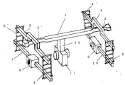
次に、添付図面に従って、本発明を実施するための最良の形態を説明する。
図1は、本発明測定装置の1例を示す斜視図であって、外枠(図示せず)に平行に支持された固定上部梁体1の2個所の刃型支点2,2´に2本の天秤型アーム3,4が該固定上部梁体1に対し左右に揺動可能に支持されている。
Next, the best mode for carrying out the present invention will be described with reference to the accompanying drawings.
FIG. 1 is a perspective view showing an example of the measuring apparatus of the present invention, in which two blade-
そして、一方のアーム3にはモータ部接続部材5,5´により駆動モータ6を取り付けたモータ固定アーム7が、またもう一方のアーム4には、負荷部接続部材8,8´により負荷プーリ9を取り付けた負荷プーリ固定アーム10がぞれぞれ支持され、さらに駆動モータ6と負荷プーリ9との中間位置に供試されるべき変速機11が固定上部梁体1に固定部材12によって配置されている。
One
この装置を用いて変速機の効率を測定するには、変速機11の入力ギヤ(図示せず)に駆動モータ6の回転軸(図示せず)を、また変速機11の出力ギヤ(図示せず)に負荷プーリ9の軸(図示せず)をそれぞれ連結する。この連結は、必要時又は不必要時に着脱可能な方式でなされている。
In order to measure the efficiency of the transmission using this device, the input gear (not shown) of the transmission 11 is connected to the rotating shaft (not shown) of the
この装置の材質としては、できるだけ変形を生じないようにし、かつ質量を小さくするために、アルミニウム又はその合金のような軽量で剛性のある金属又は合金を選ぶのが好ましい。
また、刃型支点2,2´には、カミソリ刃のような薄い板状体を用いるのが好ましい。
駆動モータ6は、モータ固定アーム7に取り付けられるが、駆動モータ6が変換自在に取り付けられるように、例えば2枚の支持板に挟み込み、固定する形式にするのが好ましい。
As a material of this device, it is preferable to select a light and rigid metal or alloy such as aluminum or an alloy thereof in order to prevent deformation as much as possible and reduce the mass.
Further, it is preferable to use a thin plate-like body such as a razor blade for the
The
この装置を用いて、変速機の効率を測定するには、先ず天秤型アーム3,4が水平になるように水準器及びレーザ変位計を用いて測定しながら、左右のバランスを調整する。この調整は、例えば軽い方に鉛のような重錘を付加することによって行われる。
In order to measure the efficiency of the transmission using this device, the balance between the left and right is first adjusted while measuring with a level and a laser displacement meter so that the
次いで、変速機11を設置後、デジタルフォースゲージをその先端が刃型支点例えばカミソリ刃に軽く触れるようにしてモータ部及び負荷プーリ部に取り付けたのち、このデジタルフォースゲージとアナライジングレコーダとを接続する。 Next, after the transmission 11 is installed, the digital force gauge is attached to the motor part and the load pulley part with its tip lightly touching the blade type fulcrum, for example, a razor blade, and then this digital force gauge is connected to the analyzing recorder. To do.
このような準備が完了したのち、電源を入れ、駆動モータ6を始動させると、モータの回転が変速機11に伝達され、さらにその回転が負荷プーリ9に伝達される。この負荷プーリ9には負荷が印加されているので天秤型アーム4が傾斜しようとする。
そして、この状態になったとき、刃型支点2´に接続しているデジタルフォースゲージにより、その際の荷重が測定される。
After completing such preparation, when the power is turned on and the
And when it will be in this state, the load in that case will be measured with the digital force gauge connected to blade type fulcrum 2 '.
一方、負荷プーリ9に負荷が印加されると、それと連動してモータ6にも負荷が印加されるので、天秤型アーム3が傾斜し、その際の荷重がデジタルフォースゲージで測定される。
このようにして得られる各天秤型アーム3,4に印加された荷重は、アナライジングレコーダに記録される。
On the other hand, when a load is applied to the
The load applied to each of the balance-
このようにして得られたデータに基づき、以下の式(1)に従って変速機の所定の変速比uにおける効率η(%)を求めることができる。
η=(1/u)・(τ0/τi) (1)
式中のτ0及τiは以下の意味をもつ。
τ0=m0g・r0 (2)
τi=mig・ri (3)
ただし
τ0:負荷側トルク(N・mm)
m0:負荷側荷重(g)
r0=負荷側の中心からデジタルフォースゲージまでの距離(mm)
g:重力加速度(kg/s2)
τi:モータ側トルク(N・mm)
mi:モータ側荷重(g)
ri:モータ側の中心からデジタルフォースゲージまでの距離(mm)
Based on the data thus obtained, the efficiency η (%) of the transmission at a predetermined gear ratio u can be obtained according to the following equation (1).
η = (1 / u) · (τ 0 / τ i ) (1)
Τ 0 and τ i in the formula have the following meanings.
τ 0 = m 0 g · r 0 (2)
τ i = m i g · r i (3)
However, τ 0 : Load side torque (N · mm)
m 0 : Load side load (g)
r 0 = distance from center of load side to digital force gauge (mm)
g: Gravity acceleration (kg / s 2 )
τ i : Motor side torque (N · mm)
m i : Motor side load (g)
r i : Distance from the center on the motor side to the digital force gauge (mm)
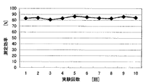
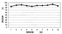
市販の減速比1/95の減速機について、6V及び9Vの電圧を印加して本発明方法により10回試験して得た測定効率(%)を図2及び図3に示す。 FIG. 2 and FIG. 3 show the measurement efficiencies (%) obtained by applying the voltages of 6V and 9V to the commercially available speed reducer with a reduction ratio of 1/95 and performing the test ten times by the method of the present invention.
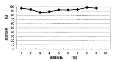
市販の減速比1/80の減速機について、6V及び9Vの電圧で駆動させ、本発明方法により10回試験して得た測定効率(%)を図4及び図5に示す。 4 and 5 show the measurement efficiencies (%) obtained by driving a commercially available speed reducer with a reduction ratio of 1/80 at a voltage of 6 V and 9 V and testing 10 times according to the method of the present invention.
これらの図から、本発明方法によれば、減速比の異なる減速機について、いずれも安定した効率の評価結果が得られることが分かる。 From these figures, it can be seen that according to the method of the present invention, stable evaluation results of the speed reducers with different reduction ratios can be obtained.
本発明によれば、種々の変速機についての効率を簡単かつ正確に算出することができるので、変速機を用いるシステムの管理に好適に利用できる。 According to the present invention, since the efficiency of various transmissions can be calculated easily and accurately, it can be suitably used for management of a system using the transmission.
1 固定上部梁体
2,2´刃型支点
3,4 アーム
5,5´モータ部接続部材
6 駆動モータ
7 モータ固定アーム
8,8´負荷部接続部材
9 負荷プーリ
10 負荷プーリ固定アーム
11 変速機
DESCRIPTION OF
Claims (2)
The drive motor and the load pulley are supported on each of the two blade-type fulcrums provided on the beam body fixed on the upper part via a balance-type support arm, and have a structure arranged opposite to each other. An apparatus for measuring efficiency of a transmission, characterized in that a transmission to be measured between them has an input gear detachably connected to a rotating shaft of a drive motor and an output gear connected to a load pulley shaft.
Priority Applications (1)
| Application Number | Priority Date | Filing Date | Title |
|---|---|---|---|
| JP2004108404A JP2005291973A (en) | 2004-03-31 | 2004-03-31 | Efficiency measuring method of speed change gear, and device used therefor |
Applications Claiming Priority (1)
| Application Number | Priority Date | Filing Date | Title |
|---|---|---|---|
| JP2004108404A JP2005291973A (en) | 2004-03-31 | 2004-03-31 | Efficiency measuring method of speed change gear, and device used therefor |
Publications (1)
| Publication Number | Publication Date |
|---|---|
| JP2005291973A true JP2005291973A (en) | 2005-10-20 |
Family
ID=35325057
Family Applications (1)
| Application Number | Title | Priority Date | Filing Date |
|---|---|---|---|
| JP2004108404A Pending JP2005291973A (en) | 2004-03-31 | 2004-03-31 | Efficiency measuring method of speed change gear, and device used therefor |
Country Status (1)
| Country | Link |
|---|---|
| JP (1) | JP2005291973A (en) |
Cited By (4)
| Publication number | Priority date | Publication date | Assignee | Title |
|---|---|---|---|---|
| JP2007271275A (en) * | 2006-03-30 | 2007-10-18 | Tdk Corp | Torque detector and detecting method |
| CN103033301A (en) * | 2012-12-24 | 2013-04-10 | 重庆理工大学 | Automated mechanical transmission (AMT) gear selecting actuator transmission efficiency measuring test method |
| CN104764488A (en) * | 2015-03-18 | 2015-07-08 | 成都飞机工业(集团)有限责任公司 | Detection device for comprehensive performance of revolution class tool |
| CN106124196A (en) * | 2016-06-14 | 2016-11-16 | 广东明阳风电产业集团有限公司 | An experimental test method for the efficiency of a wind turbine gearbox transmission chain |
Citations (7)
| Publication number | Priority date | Publication date | Assignee | Title |
|---|---|---|---|---|
| JPS5251984A (en) * | 1975-10-24 | 1977-04-26 | Chinkaku Higashijima | Power meter |
| JPS53140482U (en) * | 1977-04-13 | 1978-11-07 | ||
| JPS6133892A (en) * | 1984-07-26 | 1986-02-17 | 株式会社東芝 | Method of measuring driving torque of joint of robot |
| JPS6145946A (en) * | 1984-08-09 | 1986-03-06 | Fujitsu Ltd | Measuring instrument for efficiency of force transmission mechanism |
| JPS62112023A (en) * | 1985-11-09 | 1987-05-23 | Shinpo Kogyo Kk | Torque detecting device |
| JPH02303752A (en) * | 1989-05-19 | 1990-12-17 | Elco Co Ltd | Torque detector for machine tool |
| JPH11183277A (en) * | 1997-12-18 | 1999-07-09 | Kawatetsu Advantech Kk | Torque meter |
-
2004
- 2004-03-31 JP JP2004108404A patent/JP2005291973A/en active Pending
Patent Citations (7)
| Publication number | Priority date | Publication date | Assignee | Title |
|---|---|---|---|---|
| JPS5251984A (en) * | 1975-10-24 | 1977-04-26 | Chinkaku Higashijima | Power meter |
| JPS53140482U (en) * | 1977-04-13 | 1978-11-07 | ||
| JPS6133892A (en) * | 1984-07-26 | 1986-02-17 | 株式会社東芝 | Method of measuring driving torque of joint of robot |
| JPS6145946A (en) * | 1984-08-09 | 1986-03-06 | Fujitsu Ltd | Measuring instrument for efficiency of force transmission mechanism |
| JPS62112023A (en) * | 1985-11-09 | 1987-05-23 | Shinpo Kogyo Kk | Torque detecting device |
| JPH02303752A (en) * | 1989-05-19 | 1990-12-17 | Elco Co Ltd | Torque detector for machine tool |
| JPH11183277A (en) * | 1997-12-18 | 1999-07-09 | Kawatetsu Advantech Kk | Torque meter |
Cited By (5)
| Publication number | Priority date | Publication date | Assignee | Title |
|---|---|---|---|---|
| JP2007271275A (en) * | 2006-03-30 | 2007-10-18 | Tdk Corp | Torque detector and detecting method |
| CN103033301A (en) * | 2012-12-24 | 2013-04-10 | 重庆理工大学 | Automated mechanical transmission (AMT) gear selecting actuator transmission efficiency measuring test method |
| CN103033301B (en) * | 2012-12-24 | 2014-12-03 | 重庆理工大学 | Automated mechanical transmission (AMT) gear selecting actuator transmission efficiency measuring test method |
| CN104764488A (en) * | 2015-03-18 | 2015-07-08 | 成都飞机工业(集团)有限责任公司 | Detection device for comprehensive performance of revolution class tool |
| CN106124196A (en) * | 2016-06-14 | 2016-11-16 | 广东明阳风电产业集团有限公司 | An experimental test method for the efficiency of a wind turbine gearbox transmission chain |
Similar Documents
| Publication | Publication Date | Title |
|---|---|---|
| US7444855B2 (en) | Orthogonal rheometer | |
| CN104267617B (en) | A kind of dynamic load simulation test experiment platform and method of testing | |
| CN102680894B (en) | Performance testing system and performance testing method for portable motor | |
| KR19990070275A (en) | Apparatus and method for measuring mass moment of inertia and center of gravity | |
| EP2790003B1 (en) | Tensile testing machine | |
| JPH06509164A (en) | Compact axial torque transducer | |
| WO2014077275A1 (en) | Device for measuring dynamic characteristics of centrifugal-type rotary machine, and centrifugal-type rotary machine | |
| TW201723448A (en) | Axial rotation torque sensor allows one end of the elastic piece to sensitively produce bending and deformation under state of force received | |
| CN102879139A (en) | Turntable wire winding torque test device and test method | |
| RU2345338C1 (en) | Device for determination of performances of transmission with flexible communication | |
| CN111024516B (en) | Device for measuring structure bending moment under pure bending condition | |
| JP2008145197A (en) | Gear transmission error measuring device for gear transmission mechanism | |
| KR102330033B1 (en) | Reducer life time test apparatus | |
| RU2411496C2 (en) | Method of experimental-theoretical determination of friction performance of friction pair for torque transfer and device for implementation of this method | |
| JP2009036544A (en) | Gear noise evaluation method and apparatus for gear transmission | |
| CN209495846U (en) | Torque loading device | |
| CN108844894B (en) | Kinetic friction coefficient meter and method for measuring the kinetic friction coefficient of granules | |
| JP2007240421A (en) | Torsional rigidity computing device for rotating body, motor output computing device and methods thereof | |
| JP5133221B2 (en) | Inspection apparatus and inspection method for constant velocity universal joint | |
| CN203823031U (en) | Planetary reducer capable of carrying out torque detection at the same time | |
| JPS622252B2 (en) | ||
| JP2004132983A (en) | Balance testing machine | |
| EP1552261B1 (en) | Dual-string dynamometer for measuring dental handpiece power at high speed and low torque | |
| CN103939591A (en) | Planetary gear speed reducer capable of carrying out torque detection simultaneously | |
| CN213180676U (en) | Reducer angle transmission accuracy module testing machine |
Legal Events
| Date | Code | Title | Description |
|---|---|---|---|
| A621 | Written request for application examination |
Free format text: JAPANESE INTERMEDIATE CODE: A621 Effective date: 20070319 |
|
| RD01 | Notification of change of attorney |
Free format text: JAPANESE INTERMEDIATE CODE: A7421 Effective date: 20090608 |
|
| A131 | Notification of reasons for refusal |
Free format text: JAPANESE INTERMEDIATE CODE: A131 Effective date: 20100723 |
|
| A02 | Decision of refusal |
Free format text: JAPANESE INTERMEDIATE CODE: A02 Effective date: 20101112 |