JP2005291918A - Impactor rotation type impact inspection device - Google Patents
Impactor rotation type impact inspection device Download PDFInfo
- Publication number
- JP2005291918A JP2005291918A JP2004107335A JP2004107335A JP2005291918A JP 2005291918 A JP2005291918 A JP 2005291918A JP 2004107335 A JP2004107335 A JP 2004107335A JP 2004107335 A JP2004107335 A JP 2004107335A JP 2005291918 A JP2005291918 A JP 2005291918A
- Authority
- JP
- Japan
- Prior art keywords
- balance arm
- spring
- impactor
- striking
- return
- Prior art date
- Legal status (The legal status is an assumption and is not a legal conclusion. Google has not performed a legal analysis and makes no representation as to the accuracy of the status listed.)
- Ceased
Links
Images
Landscapes
- Investigating Or Analyzing Materials By The Use Of Ultrasonic Waves (AREA)
Abstract
【課題】 インパクターの姿勢や角度に拘らず、いかなる姿勢でも、どんな方向からでも、重力の影響を排除しながらインパクターの打撃を可能にし、また、接触時間が短く切れのよい打撃によって、対象物により高周波域で振動できるようにし、異状や変状の検出率を高くでき、精密診断に寄与するインパクター回動式打撃検査装置を提供する。
【解決手段】 一端にインパクターを備えて、枢支された回動バランスアームを、打撃ばねに抗して回動して、別途ばね付勢されて枢支されたトリガーレバーに係止し打撃待機の初期位置にセットし、トリガーレバーを操作して回動バランスアームとの係止を外し、打撃ばねにより回動バランスアームを回動して打撃し、同時に戻しばねを作用させ、打撃後、戻しばねと磁石によって二度打ちを防止し切れよい打撃を与える。
【選択図】図1PROBLEM TO BE SOLVED: To enable an impactor to be struck in any posture and from any direction regardless of the impactor's posture and angle, while eliminating the influence of gravity. Provided is an impactor rotation type impact inspection device that can vibrate in a high frequency range by an object, can increase the detection rate of abnormalities and deformations, and contributes to precise diagnosis.
SOLUTION: An impactor is provided at one end, and a pivoting balance arm is pivoted against a striking spring, and is separately strung by a trigger lever pivotally supported by a spring. Set to the initial position of standby, operate the trigger lever to unlock the rotating balance arm, rotate the rotating balance arm with the impact spring and hit it at the same time, act the return spring at the same time, after hitting, The return spring and magnet prevent double strikes and give a good blow.
[Selection] Figure 1
Description
本願発明の属する技術分野は、コンクリート構造物や鋼管の内部の空洞やクラックあるいは腐食などの異状部が存在するか否かの検査を可能とする打撃検査方法及び打撃検査装置に係り、対象物の壁面に機械的に打撃する打撃機構を用いて、打撃の反響音を解析し、異状部の位置、大きさなどを判定する装置として好適な打撃検査装置に関するものである。 The technical field to which the present invention belongs relates to a batting inspection method and a batting inspection device that can inspect whether or not there are cavities inside the concrete structure or steel pipe, cracks or corrosion, and the like. The present invention relates to a batting inspection device suitable as a device for analyzing a reverberation sound of a batting using a batting mechanism that mechanically bakes a wall surface and determining a position, a size, and the like of an abnormal portion.
検査対象の異状や変化をインパクターによる打撃や振動を印加した際の音響応答を用いて検査する従来の振動検査方法において、その音響解析法として、周波数分析法によって振動周波数の高低をもって異状診断を行ってきた。これまで、比較的低周波数領域の振動に着目していたために印加する打撃や振動は精密なものを必要としなかった。しかし、近年、検査対象の劣化により精密に診断する必要が生まれ、構造物のせん断ズレによる振動波形、弾性波の反射波形、鋼管の円周りの振動など、物理的に異なる振動モードを区別し検査をより精密にするようになった。 In the conventional vibration inspection method that inspects the abnormality or change of the inspection object using the acoustic response when impact or vibration is applied by the impactor, abnormality diagnosis is performed with the frequency of the vibration frequency as the acoustic analysis method. I went. Until now, since the focus was on vibration in a relatively low frequency region, the applied striking and vibration did not need to be precise. However, in recent years, it has become necessary to make a precise diagnosis due to deterioration of the inspection target, and distinguish and inspect physically different vibration modes such as vibration waveform due to shear deviation of structure, reflected wave of elastic wave, vibration around the circle of steel pipe, etc. Became more precise.
上述した検査方法又は検査装置において、従来のように単に手でインパクターを持ち打撃するか、或いは単純な機構を持つ器具により打撃するなどの検査方法又は検査装置では、打撃力などにバラツキがあるために、振動モードの違いを利用できる良質の音響データが得にくかったり、あるいは衝突する瞬間の接触時間が長かったり、インパクターが一旦離反した後に自らの振動で二度打ちをするなど、これらによって得られた音響データは適切に判定できない音響データとなり、目的の精密診断が困難になるなど問題を残すものであった。 In the above-described inspection method or inspection apparatus, the inspection method or inspection apparatus such as hitting and impacting the impactor with a hand or hitting with an instrument having a simple mechanism as in the prior art has variations in striking force. For this reason, it is difficult to obtain high-quality acoustic data that can use the difference in vibration mode, the contact time at the moment of collision is long, the impactor hits once with its own vibration after separating, etc. The obtained acoustic data becomes acoustic data that cannot be properly determined, and problems such as difficult precision diagnosis of the purpose remain.
特に、配管等の検査対象物が傾斜していたり、検査対象物が上方に位置していてその下面を対象にしなければならない場合など、これらの傾斜等した対象物に対して打撃検査装置の設置姿勢が変えられた場合には、打撃力などにバラツキが生じるものであった。
本願発明は、配管等の検査対象物に対する打撃検査装置の設置姿勢の如何に拘らず打撃力などにバラツキがなく、振動モードの違いを正確に把握できる良質の音響データを得るのに利用でき、且つ衝突する瞬間の接触時間が短く、インパクターが一旦離反した後の二度打ちを防止することができ、これによって適切に判定できる音響データを提供することのできる打撃検査方法及び打撃検査装置を提供する。 The invention of the present application can be used to obtain high-quality acoustic data that can accurately grasp the difference in vibration mode without any variation in the impact force regardless of the installation posture of the impact inspection device for inspection objects such as piping, Further, there is provided a hit inspection method and a hit inspection apparatus capable of preventing the double hit after the impactor is once separated from the impact time when the impact is short and thereby providing acoustic data that can be appropriately determined. provide.
本願発明の第1の目的は、インパクターの姿勢や角度による重力の影響でインパクターの回転運動の力が変化することを防ぎ、インパクターの姿勢や角度に拘らず、いかなる姿勢でも、どんな方向からでも、重力の影響を排除しながらインパクターの打撃を可能にし、常にインパクターの回転運動の力を一定にして打撃可能にすることである。 The first object of the present invention is to prevent the impactor's rotational movement force from changing due to the influence of gravity due to the impactor's posture and angle, regardless of the impactor's posture and angle, in any direction, in any direction. Therefore, the impactor can be struck while eliminating the influence of gravity, and the impactor can always be struck with a constant rotational force.
本願発明の第2の目的は、インパクターが検査対象に衝突する寸前に作動するバネにより、インパクターと検査対象の接触時間が短く切れのよい打撃によって、対象物をより高周波域で振動できるようにして、異状や変状の検出率を高くすることのできる打撃検査法及び打撃検査装置を提供することである。 The second object of the present invention is to allow the impactor to vibrate in a higher frequency range by a spring that operates immediately before the impactor collides with the inspection object, and the impact time between the impactor and the inspection object is short and can be easily cut. Thus, it is an object of the present invention to provide a batting inspection method and a batting inspection device that can increase the detection rate of abnormalities and deformations.
本願発明の第3の目的は、インパクターの回転運動の途中の経路で磁石による吸引力を活かしてインパクターの戻り速度を減速し、複合振動による2度目の打撃が発生しないようにした打撃検査装置を提供することである。 The third object of the present invention is to perform a hit inspection in which the impact force of the magnet is utilized in the path in the middle of the impactor's rotational movement to reduce the return speed of the impactor so that the second hit due to the composite vibration does not occur. Is to provide a device.
本願発明は、ケース本体に枢支され、一端にインパクターを備え他端に磁性材を備えた回動バランスアームを、打撃方向に付勢する打撃ばねに抗して回動して、ケース本体に別途ばね付勢されて枢支されたトリガーレバーに係止して打撃待機の初期位置にセットし、トリガーレバーの操作によって回動バランスアームの係止を外し、打撃ばねによって回動バランスアームを回動して所定の打撃動作をし、その際、回動バランスアームに戻しばねを作用させ、打撃後、回動バランスアームが復帰する際、戻しばねのばね力と、本体に設置の磁力によって、急速に回動バランスアームを通常略水平状態に収斂する復帰保持位置をとり二度打ちを防止することを特徴とするインパクター回動式打撃検査方法を提供する。
また、本願発明は、インパクターの突出可能な開口を有するケース本体と、ケース本体の第一枢軸に打撃ばねにより打撃方向に付勢可能に通常略水平状態に枢支され、一端にインパクターを備え他端に磁性材を備え、且つ第一枢軸を中心とした対向位置にあってその両面に互いに反対方向突出した戻し駆動ピン及び打撃駆動ピンを備えた回動バランスアームと、ケース本体の第二枢軸に枢支されトリガーレバー戻しばねにより係止方向に付勢され、一端に作動つまみを備え他端に回動バランスアームの打撃駆動ピンと係止するラッチ溝を備えたトリガーレバーと、回動バランスアームの戻し駆動ピンと係合させ、回動バランスアームをトリガーレバー戻しばねに抗して回動し、回動バランスアームをトリガーレバーに係止するセットレバーと、回動バランスアームの第一枢軸に取り付けられ、一端を本体に固定され、他端を片持ち構造をなし、第一枢軸と戻し駆動ピン心との間に位置して配設され、打撃時に戻し駆動ピンによりばね力を蓄積して戻し方向に付勢される戻しばねと、 本体に設置され、枢支される回動バランスアームの磁性材に作用して回動バランスアームを通常略水平状態に保持すると共に打撃後の傾斜した回動バランスアームを略水平状態に復元保持するマグネットとを含むことを特徴とするインパクター回動式打撃検査装置を提供する。
The present invention is pivotally supported by a case main body, and rotates a rotating balance arm having an impactor at one end and a magnetic material at the other end against a striking spring biasing in the striking direction. It is locked to a trigger lever that is separately spring-biased and pivotally supported, and is set at the initial position of the standby for hitting. The lock balance arm is unlocked by operating the trigger lever, and the rotary balance arm is locked by the striking spring. Rotate to perform a predetermined striking operation, and at that time, a return spring is applied to the rotating balance arm. After the impact, when the rotating balance arm returns, the spring force of the return spring and the magnetic force installed on the main body An impactor rotation-type impact inspection method is provided, which takes a return holding position where the rotation balance arm normally converges in a substantially horizontal state and prevents double strike.
The invention of the present application is a case main body having a projectable opening of the impactor, and is normally pivotally supported in a substantially horizontal state so as to be urged in a striking direction by a striking spring on the first pivot of the case main body. A rotating balance arm having a magnetic material at the other end and having a return drive pin and an impact drive pin projecting in opposite directions on opposite sides of the first pivot, and a first of the case body A trigger lever that is pivotally supported by two pivots and is urged in the locking direction by a trigger lever return spring, and has an operation knob at one end and a latch groove that locks the striking drive pin of the rotation balance arm at the other end, and rotation A set lever that engages with the return drive pin of the balance arm, rotates the rotary balance arm against the trigger lever return spring, and locks the rotary balance arm to the trigger lever; Attached to the first pivot of the rotating balance arm, one end is fixed to the main body, the other end has a cantilever structure, and is located between the first pivot and the return drive pin core. A return spring that accumulates spring force by the drive pin and is urged in the return direction, and is installed in the main body and acts on the magnetic material of the pivot balance arm that is pivotally supported so that the pivot balance arm is normally in a substantially horizontal state. There is provided an impactor rotation-type impact inspection apparatus characterized by including a magnet that holds and rotates and holds an inclined rotation balance arm in a substantially horizontal state after impact.
さらに、本願発明は、打撃ばねの強さを可変する調整手段を設けると共に、戻しばねの強さを可変する調整手段を設けたり、ケース本体の底面に設置時の間隙を規定する足部材を設けたり、ケース本体の底面にガイド手段を配設したり、ケース本体に少なくとも一つの取手を有したインパクター回動式打撃検査装置をも提供する。 Further, the present invention provides an adjusting means for changing the strength of the impact spring, an adjusting means for changing the strength of the return spring, and a foot member for defining a gap at the time of installation on the bottom surface of the case body. There is also provided an impactor turning-type impact inspection device in which guide means is disposed on the bottom surface of the case body, or at least one handle is provided on the case body.
本願発明によれば、打音によって異状や変状を検出するための打音検査装置において、
インパクターの姿勢や角度による重力の影響でインパクターの回転運動の力が変化することを防ぎ、インパクターの姿勢や角度に拘らず、いかなる姿勢でも、どんな方向からでも、重力の影響を排除しながらインパクターの打撃を可能にし、常にインパクターの回転運動の力を一定にして打撃可能にすることである。
According to the present invention, in the sound-inspecting device for detecting abnormalities and deformations by sound,
It prevents the impactor's rotational movement force from changing due to the impact and gravity of the impactor, and eliminates the influence of gravity from any orientation, regardless of the impactor's orientation and angle. The impactor can be struck while the force of the impactor's rotational motion is always kept constant.
また、本願発明によれば、インパクターが検査対象に衝突する寸前に作動するバネにより、インパクターと検査対象の接触時間が短く切れのよい打撃によって、対象物をより高周波域で振動できるようにして、異状や変状の検出率を高くすることができる。 Further, according to the present invention, the spring that operates immediately before the impactor collides with the inspection object enables the object to vibrate in a higher frequency range by a short hit with a short contact time between the impactor and the inspection object. Thus, the detection rate of abnormalities and deformations can be increased.
さらに、本願発明によれば、インパクターの回転運動の途中の経路で磁石による吸引力を活かしてインパクターの戻り速度を減速し、複合振動による2度目の打撃が発生しないようにすることができる。 Furthermore, according to the present invention, the return speed of the impactor can be reduced by utilizing the attractive force of the magnet in the path in the middle of the rotational movement of the impactor, so that the second blow due to the combined vibration can be prevented. .
本願発明によれば、第一枢軸に巻回した打撃ばねの打撃駆動ピン当接する一端と反対側の他端を、ケース本体に対し、第一枢軸を中心とした所定半径の周方向に位置調整可能に取り付けることによって、打撃ばねの強さを調整することができる。 According to the present invention, the other end of the striking spring wound around the first pivot and the other end opposite to the one that contacts the striking drive pin is adjusted with respect to the case body in the circumferential direction with a predetermined radius centered on the first pivot. The strength of the striking spring can be adjusted by mounting it as possible.
また、第二枢軸に巻回し、戻し駆動ピンに当接する一端と反対側の他端を、ケース本体に対し、第一枢軸を中心として一定周方向に位置調整可能に取り付けることによって、戻しばねの強さを調整することができる。 In addition, the other end of the return spring that is wound around the second pivot and that is opposite to the one end that contacts the return drive pin is attached to the case body so that the position of the return spring can be adjusted in a certain circumferential direction around the first pivot. The strength can be adjusted.
ケース本体1の底面を被検査材の打撃面に沿わせることによって、所定の値に設定されて打撃力で打撃面を打撃し、をすることができる。
ケース本体1の底面に設置時の間隙を規定する足部材30を設けることによって打撃力を所定の値に設定することができる。
By setting the bottom surface of the
The striking force can be set to a predetermined value by providing a
ケース本体1の側方下方に向けたガイド手段31を配設することによって、パイプ等の配管に対し迅速にかつ確実に適用することが可能である。
ケース本体1に少なくとも上面及び側面にハンドルを取り付けた場合には両方の取手により傾斜した配管に対しても回動式打撃検査装置を容易に適用することができる。
By disposing the guide means 31 directed to the lower side of the
When the handle is attached to the
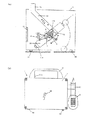
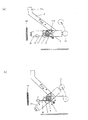
本発明の打撃検査装置は図1にその概要が示される。
図1(b)は打撃検査装置の外観を示し、本体ケース1は角形をなし、上面に第一ハンドル1aを有し、第一ハンドル1aの背後に位置してトリガーレバーの操作摘み12aが揺動可能に突出して設けられ、図右側面のマイク支持部材20に集音マイク3がセットされ、正面にセットレバー摘み29が揺動操作可能に設けられている。本体ケース1内には、図1(a)に示す打撃検査装置の模式図とともに、その打撃検査方法の原理が模式的に示される。以下この図1bの模式図を用いて説明する。
An outline of the impact inspection apparatus of the present invention is shown in FIG.
FIG. 1 (b) shows the external appearance of the impact inspection apparatus. The
回動バランスアーム10はその一端にインパクター11を備えると共に他端に磁性材11aを備え、ケース本体1に第一枢軸4により枢支され、打撃ばね8により打撃方向へ付勢可能に配置される。一方、トリガーレバー12は、ケース本体1の第2枢軸に別途ばねにより第一枢軸4の方向に付勢して枢支される。
The rotating
また、回動バランスアームの第一枢軸には戻しばね9が取り付けられ、戻しばね9の一端を本体に固定位置調整可能に取り付けられ、他端を片持ち構造となし、回動バランスアームの戻し駆動ピン7との間に所定の間隔を置いて配設されており、打撃時に戻し駆動ピンによりばね力を蓄積して戻し方向に付勢される。
Further, a
さらに本体には、マグネット18が設置され、第一枢軸4に枢支されたインパクター11を備える回動バランスアーム10の他端の磁性材と吸引し合っている。
したがって、回動バランスアーム10は、打撃駆動ピン6を介した戻しばね9の力と、回動バランスアーム10の他端磁性材のマグネット18による吸引力とのバランスの下に、図面略水平に支持される。回動バランスアーム10は、後述するように本体に固定される固定端が調節可能に取り付けられ、戻しばね力を調節することができるので、これに伴って回動バランスアーム10の水平位置は変化させられるので、以下「略水平」とは、この戻しばね力とマグネット吸引力によって定まるケース1の底面に対する図示略水平位置をとることを意味するものです。
Further, a
Therefore, the
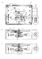
回動バランスアーム10は、詳細には、図2(a)及び(c)に示すように、第一枢軸の左側で手前に延びる戻し駆動ピン7を備えると共に第一枢軸の戻し駆動ピン7側と反対側(図面右側)の位置でその後方に延びる打撃駆動ピン6を備え、回動バランスアーム10とトリガーレバー12の間の第一枢軸4部分に巻回して備えた打撃ばね8の一方の開放端部が打撃駆動ピン6に当接し、打撃ばね8の他方の端部は本体ケースに調節可能に固定されている。これにより、第一枢軸4に配設された打撃ばね8による回動バランスアーム10の付勢力は、回動バランスアーム10が図面左方向に回動されて打撃待機位置にもたらされたとき、打撃ばね8が打撃駆動ピン6に当接しながら圧縮されることによって蓄積される。
Specifically, as shown in FIGS. 2A and 2C, the
トリガーレバー12は、詳細には、図2(a)及び(b)に示すように、本体1の第2枢軸22に巻回して取り付けたトリガーレバー戻しばね13により第一枢軸4の方向に付勢して枢支されているので、回動バランスアーム10が図面左回動方向に回動すると、トリガーレバー12を打撃駆動ピン6で押し上げながらばね13に抗して回動し、打撃駆動ピン6を係止溝12bに係止する。これにより、回動バランスアーム10はその打撃駆動ピン6をトリガーレバーの係止溝12bに係止した打撃待機位置にセットされる。
Specifically, as shown in FIGS. 2A and 2B, the
なお、打撃待機位置にセットする操作は、図1(a)(b)及び図2(c)に示すように、本体ケース1正面のセットレバー28の摘み29を揺動操作すればよく、摘み29を揺動操作によって押金27、戻し駆動ピン7を介して回動バランスアーム10が回動され、打撃駆動ピン6をトリガーレバー12に沿って押し上げ、トリガーレバー12の係止溝12bの位置において自動的に係止させ打撃待機位置にセットされる。
As shown in FIGS. 1 (a), 1 (b) and 2 (c), the operation of setting the hitting standby position may be performed by swinging the
戻しばね9は、詳細には、図2(a)及び(c)に示すように、回動バランスアーム10の第一枢軸4の手前側に巻回して取り付けられ、戻しばね9の一端は取り付け金具を介して本体に固定位置調整可能に取り付けられ、戻しばね9他端は、回動バランスアーム10の戻し駆動ピン7との間に所定の間隔を置いて配設されている。打撃時、回動バランスアーム10が釈放され、インパクター11が打撃位置へと回動すると、戻しばね9は回動バランスアーム10の戻し駆動ピン7に途中から接触し駆動ピン7更なる回動によりばね力が蓄積される。これにより、打撃位置において、回動バランスアーム10は戻し方向に付勢される。
In detail, as shown in FIGS. 2A and 2C, the
戻しばね9一端の固定位置調整可能な取り付けによって、戻しばね9と戻し駆動ピン7との当接のタイミングを変更し、蓄積される戻しばね9の反発力を変更することができる。
マグネット18は、詳細には、図2(a)及び(c)に示すように、本体1にシャーシ2を介して取り付けた取付金具2によって、第一枢軸4に枢支されたインパクター11を備える回動バランスアーム10の回動軌跡に近傍において取り付けられ、マグネット18の取り付け位置は、図1(a)に示すように、マグネット18と第一枢軸4に枢支された回動バランスアーム10が略水平の状態で最大の吸引力が作用する位置、板状のマグネット18の中心と第一枢軸4を結ぶ線が、たとえば配管に代表される打撃面と平行をなす位置に設定される。したがって、打撃待機位置にセットされた回動バランスアーム10が釈放され、打撃し、その後の復帰保持位置は図面略水平に支持される。
By attaching the one end of the
Specifically, as shown in FIGS. 2 (a) and 2 (c), the
以上本願発明においては、一端にインパクター11を備え他端に磁性材11aを備え、ケース本体1に第一枢軸4に枢支された回動バランスアーム10を、摘み29の操作によって、打撃方向に付勢する打撃ばね8に抗して回動し、別途トリガレバー戻しばね13により付勢されて枢支されたトリガーレバー12に係止して打撃待機位置にセットし、トリガーレバー12の操作によって回動バランスアーム10との係止を外し、打撃ばね8によって回動バランスアーム10を回動して所定の打撃動作を行い、その際、回動バランスアームに戻しばねを作用させ、打撃後、回動バランスアームが復帰する際、戻しばね9のばね力と、マグネット18の磁力によって、急速に回動バランスアーム10を通常略水平状態に収斂する復帰保持位置をとり、回動バランスアーム10のインパクター11による二度打ちを確実に防止する。
As described above, in the present invention, the
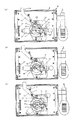
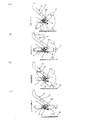
図3は、本発明に係る打撃検査装置を打撃待機位置にセットするときの一連の操作状態を示す。図3(a)に示す復帰保持位置では、回動バランスアーム10はマグネット18の吸引作用を受けて中立状態にあり、摘み29先端の押金27は戻し駆動ピン7と離れており、戻しばね9も戻し駆動ピン7と離れ、戻しばね力は作用しておらず、打撃駆動ピン6はトリガーレバー12の係止溝12bとの係合が解除されている。
FIG. 3 shows a series of operation states when the batting inspection apparatus according to the present invention is set at the batting standby position. In the return holding position shown in FIG. 3 (a), the
図3(b)に示す打撃待機位置へ移行位置では、摘み29を操作してセットレバー28先端の押金27を回動バランスアーム10の戻し駆動ピン7に当接させ、他方では回動バランスアーム10の打撃駆動ピン6をトリガーレバー12に当接させ、セットレバー摘み29の回動操作により、回動バランスアーム10をトリガーレバー12に係止する打撃待機位置へ移行する可能な状態が示される。この時点において、戻しばね9は戻し駆動ピン7と離れていて、戻しばね力は作用していない、
図3(c)のセットされた打撃待機位置では、セットレバー28さらに回動し、押金27を戻し駆動ピン7に当接させながら回動バランスアーム10左側を押し下げると共に、端部のインパクター11を上方に回動し、回動バランスアーム10の打撃駆動ピン6をトリガーレバー12の係止溝12bにもたらした位置で、トリガーレバー戻しばね13の作用でトリガーレバー12を点線矢印の方向に回動し、打撃駆動ピン6は係止溝12bに係止される。この位置でも、戻しばね9は戻し駆動ピン7と離れ、戻しばね力は作用していない。
In the transition position to the impact standby position shown in FIG. 3 (b), the
3C, the
図4は、本発明の打撃検査装置を打撃待機位置にセットするときの回動バランスアーム10とトリガーレバー12との一連の係合操作過程におけるトリガーレバー戻しばね13の関係を示す。トリガーレバー戻しばね13は、図4(a)に示すように、トリガーレバー12を枢支する第二枢軸22に巻回して装着され、一端を本体ケース1に固定のストッパー14に係合し、他端をトリガーレバー12のトリガーレバー駆動ピン21に係合し、したがって、トリガーレバー戻しばね13は、第二枢軸22を中心にしてトリガーレバー12を常に図示右回動方向に付勢する負荷力が与えられている。そこで、係止を解除され、打診検査を終了し、マグネット18の吸引作用を受ける図4(a)に示す中立状態では、トリガーレバー12は常時回動バランスアーム10の打撃駆動ピン6に当接しているので、回動バランスアーム10の回動により打撃駆動ピン6を介してトリガーレバー12を戻しばね13に抗して作動可能な状態となっている。また、図4(b)の打撃待機位置では、セットレバー12を回動バランスアームにより回動操作してトリガーレバーに係止し打撃待機状態にもたらしたときのトリガーレバー戻しばねの状態を示す図である。
FIG. 4 shows the relationship of the trigger
図5は、本発明の打撃待機位置にセットするため、回動バランスアーム10とトリガーレバー12との一連の係合過程における打撃ばね8と戻しばね9の関係を示す図である。
打診検査を終了し、回動バランスアーム10が打撃面に平行な中立状態にあるときには、図5(a)に示すように、打撃ばね8は図面左側端部がケース本体に固定され、右側端部は打撃駆動ピン6に添って位置され、回動バランスアーム10はマグネット18の吸引作用を受けてマグネット18の面と略垂直状に位置される。回動バランスアーム10が打撃待機位置にセットされた状態では、図5(b)に示すように、打撃ばね8のフリーとなった左側端部は打撃駆動ピン6により曲げられ、打撃のためのばね力が蓄積される。図5(a)の中立状態から図5(a)に示す打撃待機位置まで操作において、戻しばね9は戻し駆動ピン7による曲げ作用を受けることはない。
FIG. 5 is a view showing the relationship between the
When the percussion examination is completed and the
図6は、本発明の打撃待機位置から係止を解除して打撃し、中立の復帰保持位置に至るまでの一連の動作を示す模式図である。
図6(a)の打撃待機位置にセットされた状態では、回動バランスアーム10は打撃ばね8の付勢力を蓄積した状態でトリガーレバー12に係止され、戻しばね9はフリーとなっている。図6(b)の係止が解除され打撃位置へと進行している途中の状態では、回動バランスアーム10は打撃ばね8の蓄積した付勢力を受けてトリガーレバー12は矢印の方向に回動した略水平状態の位置を示し、このときもまだ戻しばね9はフリーとなっている。図6(c)の被検査材を打撃した状態では、回動バランスアーム10は打撃ばね8の付勢力から解放され、インパクター11を備えた回動バランスアーム10の慣性で打撃面を打撃し、その際、トリガーレバー12は、図3(c)で示すストッパー14により停止した位置に保持され、戻しばね9は戻し駆動ピン7により曲げ力を受け、回動バランスアーム10の戻り動作のためのばね力が蓄積される。打撃後に反転動作し、図6(d)の復帰保持位置になった状態では、回動バランスアーム10は打撃ばね8の作用を受けず、また戻しばね9の作用も受けず、マグネット18の吸着力のみの支配下にある状態に急速に収斂した中立位置となる。
FIG. 6 is a schematic diagram showing a series of operations from the hitting standby position according to the present invention to releasing the lock and hitting to the neutral return holding position.
In the state set in the striking standby position in FIG. 6A, the
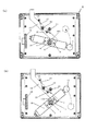
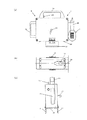
図7は、本願発明の別の実施例を示す。本体ケース1は、前記実施例と同様に、第1ハンドル1a、トリガレバーの操作摘み12a、セットレバー摘み29、マイク支持部材20を有し、その底面に、インパクター11が突出する開口が形成されている。この実施例ではさらに、本体ケース1の側面で、マイク支持部材20の反対側側面に第二ハンドル1bが取り付けられる。また、本体ケース1の底面には、長手方向両端部近傍に長手方向と直交する足部材30、30が横断的に取り付けられる。さらに、長手方向側面にそれぞれ底下方に伸びるガイド31、31が設けられている。
FIG. 7 shows another embodiment of the present invention. The
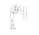
この第2の実施例によれば、第1ハンドル1a及び第2ハンドルの両者を把持して、特に傾斜した被検査材、又は頭上に位置して下向きの表面を検査対象とする被検査材の場合には、2つハンドルで容易に位置調整して設置することができるので、打撃検査が容易にできる。長手方向側面に設けたガイド31、31により、配管に対して容易にかつ適切に設置することができるので、斜傾した配管に対する適応においては特に効果的である。
According to the second embodiment, both the first handle 1a and the second handle are grasped, and particularly the inspected material to be inspected, or the inspected material that is located above the head and has a downward surface to be inspected. In this case, since the position can be easily adjusted and installed with two handles, the hit inspection can be easily performed. Since the
また、本体ケース1の底面設けた足部材30、30が横断的に取り付けられているので、本体ケース底の開口から突出するインパクター11の距離を一定にすることができるので常にインパクター11の打撃力を所定の設定値に設定することができるので、安定した検査値が、確実に得られる。
Further, since the
1 ケース
1a 第1ハンドル
1b 第2ハンドル
2 シャーシ
2a 取り付け金具
3 集音マイク
4 第一枢軸
5 ホルダー付きベアリング
6 打撃駆動ピン
7 戻し駆動ピン
8 打撃ばね
9 戻しばね
10 回動バランスアーム
11 インパクター(インパクター)
12 トリガーレバー
12a 操作摘み
12b 係止溝
13 トリガーレバー戻しばね
14 ストッパー
15 ストッパー
16 戻しばね調整リング
17 打撃力調整金具
18 マグネット
19 被検査材
20 マイク支持部材
21 トリガーレバー駆動ピン
22 第二枢軸
23 セットレバー戻し駆動ピン
24 セットレバー戻しばね
25 セットレバー回動軸
26 セットレバー金具
27 押金
28 セットレバー
29 摘み
30 足部材
31 ガイド
H 打撃検査装置
DESCRIPTION OF
12
H Blow inspection device
Claims (7)
7. The impactor rotation type hammering inspection apparatus according to claim 2, wherein the case main body has at least one handle.
Priority Applications (1)
| Application Number | Priority Date | Filing Date | Title |
|---|---|---|---|
| JP2004107335A JP2005291918A (en) | 2004-03-31 | 2004-03-31 | Impactor rotation type impact inspection device |
Applications Claiming Priority (1)
| Application Number | Priority Date | Filing Date | Title |
|---|---|---|---|
| JP2004107335A JP2005291918A (en) | 2004-03-31 | 2004-03-31 | Impactor rotation type impact inspection device |
Publications (1)
| Publication Number | Publication Date |
|---|---|
| JP2005291918A true JP2005291918A (en) | 2005-10-20 |
Family
ID=35325006
Family Applications (1)
| Application Number | Title | Priority Date | Filing Date |
|---|---|---|---|
| JP2004107335A Ceased JP2005291918A (en) | 2004-03-31 | 2004-03-31 | Impactor rotation type impact inspection device |
Country Status (1)
| Country | Link |
|---|---|
| JP (1) | JP2005291918A (en) |
Cited By (7)
| Publication number | Priority date | Publication date | Assignee | Title |
|---|---|---|---|---|
| JP2016205900A (en) * | 2015-04-17 | 2016-12-08 | 株式会社フジタ | Inspection object state evaluation system |
| CN108562356A (en) * | 2017-12-22 | 2018-09-21 | 东方通信股份有限公司 | A kind of vibration invading detector verifying attachment |
| KR20190056786A (en) * | 2017-11-17 | 2019-05-27 | 한국식품연구원 | Nondestructive quality measurement equipment using percussion sound |
| JP2021006828A (en) * | 2020-10-21 | 2021-01-21 | 株式会社フジタ | Condition evaluation device for inspection objects |
| JP2021009164A (en) * | 2020-10-21 | 2021-01-28 | 株式会社フジタ | State evaluation apparatus of test object |
| CN113640508A (en) * | 2021-07-19 | 2021-11-12 | 安徽桐康医疗科技股份有限公司 | Detection plate for fluorescence immunoassay quantitative analyzer |
| CN117723637A (en) * | 2024-02-09 | 2024-03-19 | 同济大学 | Tunnel contact detection system and its periodic shock wave excitation device |
-
2004
- 2004-03-31 JP JP2004107335A patent/JP2005291918A/en not_active Ceased
Cited By (12)
| Publication number | Priority date | Publication date | Assignee | Title |
|---|---|---|---|---|
| JP2016205900A (en) * | 2015-04-17 | 2016-12-08 | 株式会社フジタ | Inspection object state evaluation system |
| KR20190056786A (en) * | 2017-11-17 | 2019-05-27 | 한국식품연구원 | Nondestructive quality measurement equipment using percussion sound |
| KR102074400B1 (en) | 2017-11-17 | 2020-02-14 | 한국식품연구원 | Nondestructive quality measurement equipment using percussion sound |
| CN108562356A (en) * | 2017-12-22 | 2018-09-21 | 东方通信股份有限公司 | A kind of vibration invading detector verifying attachment |
| JP2021006828A (en) * | 2020-10-21 | 2021-01-21 | 株式会社フジタ | Condition evaluation device for inspection objects |
| JP2021009164A (en) * | 2020-10-21 | 2021-01-28 | 株式会社フジタ | State evaluation apparatus of test object |
| JP7018636B2 (en) | 2020-10-21 | 2022-02-14 | 株式会社フジタ | Condition evaluation device for inspection objects |
| JP7029146B2 (en) | 2020-10-21 | 2022-03-03 | 株式会社フジタ | Condition evaluation device for inspection objects |
| CN113640508A (en) * | 2021-07-19 | 2021-11-12 | 安徽桐康医疗科技股份有限公司 | Detection plate for fluorescence immunoassay quantitative analyzer |
| CN113640508B (en) * | 2021-07-19 | 2024-02-27 | 安徽桐康医疗科技股份有限公司 | Detection plate for fluorescent immunity quantitative analyzer |
| CN117723637A (en) * | 2024-02-09 | 2024-03-19 | 同济大学 | Tunnel contact detection system and its periodic shock wave excitation device |
| CN117723637B (en) * | 2024-02-09 | 2024-04-19 | 同济大学 | Tunnel contact detection system and periodic shock wave excitation device |
Similar Documents
| Publication | Publication Date | Title |
|---|---|---|
| JP2005291918A (en) | Impactor rotation type impact inspection device | |
| KR20020018198A (en) | Method and apparatus for locating and aligning golf club shaft spine | |
| HK1045020B (en) | Disk unit | |
| CN110082199A (en) | Percussion device and intrinsic frequency measurement device | |
| JPWO2017175446A1 (en) | Rotating electric machine wedge impact device and rotating electric machine wedge inspection system | |
| US20220161405A1 (en) | Retaining device for use with a nail gun | |
| JP6387031B2 (en) | Concrete sounding device and concrete inspection method using the same | |
| JPH07261745A (en) | Piano sound stop | |
| JP7312102B2 (en) | Hammering test device | |
| JP3822801B2 (en) | Hitting device and method used for evaluation of soundness of concrete | |
| JP3831300B2 (en) | Blowing device and striking method | |
| JP7362068B2 (en) | Non-destructive testing method and non-destructive testing device for concrete structures | |
| US11738431B2 (en) | Retaining device for use with a nail gun | |
| JP3739896B2 (en) | Impact device for wall peeling diagnostic machine | |
| JP6758010B1 (en) | Strike device | |
| JP2012172997A (en) | Agitation apparatus for concrete pole | |
| KR101451198B1 (en) | Rapping device for a scale removal of heat exchanger | |
| JPH10153099A (en) | Strength measuring method and device for sprayed concrete | |
| EP4029653B1 (en) | Retaining device for use with a nail gun | |
| US20240165479A1 (en) | Golf Ball Putting Practice Apparatus | |
| KR200183458Y1 (en) | A impacting apparatus for testing non-destruction of concrete | |
| JPH0538549U (en) | Excitation device for experimental modal analysis | |
| JP2003084753A (en) | Piano silencer | |
| JP4116501B2 (en) | Launch angle adjustment mechanism of bullet ball game machine | |
| JP4111882B2 (en) | Launch angle adjustment mechanism of bullet ball game machine |
Legal Events
| Date | Code | Title | Description |
|---|---|---|---|
| A521 | Written amendment |
Effective date: 20070330 Free format text: JAPANESE INTERMEDIATE CODE: A821 |
|
| A621 | Written request for application examination |
Effective date: 20070330 Free format text: JAPANESE INTERMEDIATE CODE: A621 |
|
| A01 | Written decision to grant a patent or to grant a registration (utility model) |
Effective date: 20100302 Free format text: JAPANESE INTERMEDIATE CODE: A01 |
|
| A045 | Written measure of dismissal of application |
Free format text: JAPANESE INTERMEDIATE CODE: A045 Effective date: 20100727 |