JP2005291901A - Lens meter - Google Patents

Lens meter Download PDF

Info

Publication number
JP2005291901A
JP2005291901A JP2004106805A JP2004106805A JP2005291901A JP 2005291901 A JP2005291901 A JP 2005291901A JP 2004106805 A JP2004106805 A JP 2004106805A JP 2004106805 A JP2004106805 A JP 2004106805A JP 2005291901 A JP2005291901 A JP 2005291901A
Authority
JP
Japan
Prior art keywords
lens
light
measurement
receiving element
projecting
Prior art date
Legal status (The legal status is an assumption and is not a legal conclusion. Google has not performed a legal analysis and makes no representation as to the accuracy of the status listed.)
Pending
Application number
JP2004106805A
Other languages
Japanese (ja)
Inventor
Satoshi Imaizumi
智 今泉
Current Assignee (The listed assignees may be inaccurate. Google has not performed a legal analysis and makes no representation or warranty as to the accuracy of the list.)
Nidek Co Ltd
Original Assignee
Nidek Co Ltd
Priority date (The priority date is an assumption and is not a legal conclusion. Google has not performed a legal analysis and makes no representation as to the accuracy of the date listed.)
Filing date
Publication date
Application filed by Nidek Co Ltd filed Critical Nidek Co Ltd
Priority to JP2004106805A priority Critical patent/JP2005291901A/en
Publication of JP2005291901A publication Critical patent/JP2005291901A/en
Pending legal-status Critical Current

Links

Images

Landscapes

  • Testing Of Optical Devices Or Fibers (AREA)

Abstract

<P>PROBLEM TO BE SOLVED: To provide a lens meter for stabilizing measurement precision without being affected by the difference in the power of a lens to be inspected. <P>SOLUTION: The lens meter comprises a nose piece for placing the lens to be inspected at a prescribed position; a light projection optical system that has a light projection lens system for projecting a measurement luminous flux from a measurement light source to the lens to be inspected and projects at least three measurement luminous fluxes to the lens to be inspected; and a two-dimensional light receiving element arranged at a position for receiving the measurement luminous flux after being transmitted through the lens to be inspected without going through an image optical system, thus measuring the optical characteristics of the lens to be inspected on the basis of the output of the two-dimensional light receiving element. The light projection lens system is arranged so that the measurement light source and an area near the lens to be inspected placed at the nose piece are in a conjugate relationship. <P>COPYRIGHT: (C)2006,JPO&NCIPI

Description

本発明は、被検レンズの光学特性を測定するレンズメータに関する。   The present invention relates to a lens meter that measures optical characteristics of a lens to be examined.

レンズメータとしては、光源からの測定光束をコリメータレンズで平行光束として被検レンズに投光し、被検レンズを通過した後の光束を少なくとも3個の開口及びこの開口にそれぞれ配設した収束レンズを介して2次元受光素子に投影し、受光素子に投影された開口のスポット像の位置を検出することにより、被検レンズの光学特性を測定するものが知られている(特許文献1参照)。
特開平11−255581号
As a lens meter, a measurement light beam from a light source is projected onto a test lens as a parallel light beam by a collimator lens, and the light beam after passing through the test lens is provided with at least three apertures and converging lenses respectively disposed in the apertures Is known that measures the optical characteristics of a lens to be measured by projecting to a two-dimensional light receiving element via the sensor and detecting the position of the spot image of the aperture projected on the light receiving element (see Patent Document 1). .
Japanese Patent Laid-Open No. 11-255581

しかし、上記のようなレンズメータにおいては、受光素子上のスポット像のサイズ及び光量が被検レンズの度数により変化する問題があった。例えば、開口にそれぞれ配設した収束レンズによる収束光が、0D度数のときに受光素子上で集光するような配置とした場合、被検レンズが高度数になる程、受光素子上のスポット像のサイズは広がり、光量は低下する。受光素子のダイナミックレンジが狭いと、0D度数の付近で十分な階調がとれても、高度数になる程スポット像の光量が低下し、階調がとれずに、スポット像の位置検出精度の低下を招く問題がある。   However, in the lens meter as described above, there is a problem that the size and the light amount of the spot image on the light receiving element vary depending on the power of the test lens. For example, when the converging light from the converging lenses respectively disposed at the apertures is arranged to be condensed on the light receiving element when the power is 0D, the spot image on the light receiving element becomes higher as the test lens becomes higher in number. Increases in size and the amount of light decreases. If the dynamic range of the light receiving element is narrow, even if a sufficient gradation can be obtained in the vicinity of the 0D power, the light amount of the spot image decreases as the altitude increases, and the position detection accuracy of the spot image is reduced without gradation. There is a problem that causes a drop.

本発明は、上記問題点を鑑み、被検レンズの度数の違いの影響を受けず、測定精度の安定化を図ることができるレンズメータを提供することを技術課題とする。   In view of the above problems, an object of the present invention is to provide a lens meter that can stabilize measurement accuracy without being affected by the difference in the power of the lens to be examined.

(1) 被検レンズを所定の位置に載置するためのノーズピースと、測定光源からの測定光束を被検レンズへ投光する投光レンズ系を持ち、被検レンズに対して少なくとも3つの測定光束を投光する投光光学系と、被検レンズを透過した後の測定光束を結像光学系を介さずに受光する位置に配置された2次元受光素子とを備え、前記2次元受光素子の出力に基づいて被検レンズの光学特性を測定するレンズメータであって、前記投光レンズ系は、前記測定光源とノーズピースに載置される被検レンズ付近とが共役関係となるように配置されていることを特徴とする。
(2) (1)のレンズメータにおいて、前記投光光学系は前記測定光源と投光レンズ系との間に配置され、且つ前記投光レンズ系の像側焦点位置に配置された絞りを備え、前記測定光源は少なくとも3個配置されていることを特徴とする。
(3) (2)のレンズメータにおいて、前記絞りの径を変化させる絞り径可変手段と、前記2次元受光素子の出力に基づいて前記絞り径可変手段を制御する制御手段と、を備えることを特徴とする。
(4) (1)の投光レンズ系は、コリメータレンズと、該コリメータレンズを通過した前記測定光源からの光をリング状に制限して被検レンズに集光するリングレンズと、を持つことを特徴とする。
(1) A nosepiece for placing the test lens at a predetermined position, and a light projecting lens system for projecting the measurement light beam from the measurement light source to the test lens, and at least three for the test lens A light projecting optical system for projecting the measurement light beam, and a two-dimensional light receiving element disposed at a position for receiving the measurement light beam after passing through the test lens without passing through the imaging optical system. A lens meter for measuring optical characteristics of a test lens based on an output of an element, wherein the projection lens system has a conjugate relationship between the measurement light source and the vicinity of the test lens placed on a nosepiece. It is characterized by being arranged.
(2) In the lens meter of (1), the light projecting optical system includes a stop disposed between the measurement light source and the light projecting lens system and disposed at an image side focal position of the light projecting lens system. , At least three measurement light sources are arranged.
(3) The lens meter according to (2), further comprising: a diaphragm diameter varying unit that changes the diameter of the diaphragm; and a control unit that controls the diaphragm diameter varying unit based on an output of the two-dimensional light receiving element. Features.
(4) The projection lens system according to (1) includes a collimator lens and a ring lens that condenses the light from the measurement light source that has passed through the collimator lens in a ring shape and collects the light on the lens to be examined. It is characterized by.

本発明によれば、被検レンズの度数の違いの影響を受けずに、測定精度の安定化を図ることができる。   According to the present invention, it is possible to stabilize the measurement accuracy without being affected by the difference in the power of the test lens.

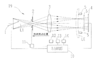
以下、本発明の実施形態を図面に基づいて説明する。図1は、本実施例におけるレンズメータの光学系及び制御系を示す概略構成図である。   Hereinafter, embodiments of the present invention will be described with reference to the drawings. FIG. 1 is a schematic configuration diagram showing an optical system and a control system of a lens meter in the present embodiment.

19は被検レンズLEに測定光束を投光する投光光学系であり、順に、測定光源1、可変絞り2、投光レンズ3により構成されている。測定光源1は白色LEDからなり、測定光軸L1から等距離の位置に90度間隔で4つ配置されている。可変絞り2は絞りの径が可変であり、投光レンズ3の光軸L1を中心とした円形の開口により光源1からの測定光束を制限する。投光レンズ3は光源1からの測定光束を被検レンズLEへ投光する。可変絞り2は投光レンズ3の物側焦点位置に配置され、可変絞り2と投光レンズ3は像側テレセントリック光学系を構成している。   Reference numeral 19 denotes a light projecting optical system for projecting a measurement light beam onto the lens LE to be measured, which is composed of a measurement light source 1, a variable aperture 2, and a light projecting lens 3 in this order. The measurement light source 1 is composed of a white LED, and four measurement light sources 1 are arranged at equal intervals from the measurement optical axis L1 at intervals of 90 degrees. The variable aperture 2 has a variable aperture diameter, and restricts the measurement light beam from the light source 1 by a circular opening centered on the optical axis L1 of the light projecting lens 3. The light projecting lens 3 projects the measurement light beam from the light source 1 onto the lens LE to be examined. The variable aperture 2 is disposed at the object side focal position of the light projecting lens 3, and the variable aperture 2 and the light projecting lens 3 constitute an image side telecentric optical system.

5は被検レンズLEを載置するためのノーズピースである。6はe線(546.07nm)付近のみのを通過させるバンドパスフィルタである。4は2次元受光素子である。投光レンズ3は、光源1とノーズピース5上に配置される被検レンズLE付近とが共役関係となるように配置されている(必要な精度との関係で略共役となれば良い)。   Reference numeral 5 denotes a nosepiece for placing the test lens LE. Reference numeral 6 denotes a band-pass filter that passes only near the e-line (546.07 nm). Reference numeral 4 denotes a two-dimensional light receiving element. The light projecting lens 3 is arranged so that the light source 1 and the vicinity of the lens LE to be arranged on the nosepiece 5 have a conjugate relationship (it should be substantially conjugate in relation to the required accuracy).

各光源1からの光は、可変絞り2、投光レンズ3を介して4本の収束光束となって、被検レンズLEに投光される。そして、被検レンズLEを透過した4本の測定光束は、レンズ等の結像光学系を介さずに直接二次元受光素子4に受光され、二次元受光素子4上には4つの測定光束によるスポット像が投影される。二次元受光素子4からの出力信号は制御部10へと入力され、制御部10は所定の演算を行って被検レンズLEの光学特性を得る。また、制御部10には、可変絞り2の絞りの径を変えるための絞り駆動部11、メモリ12、測定結果等を表示するモニタ13、スイッチ部14が接続されている。   The light from each light source 1 becomes four convergent light beams via the variable aperture 2 and the light projecting lens 3, and is projected onto the lens LE. The four measurement light beams transmitted through the test lens LE are directly received by the two-dimensional light receiving element 4 without passing through an imaging optical system such as a lens, and the four measurement light beams are formed on the two-dimensional light receiving element 4. A spot image is projected. An output signal from the two-dimensional light receiving element 4 is input to the control unit 10, and the control unit 10 performs a predetermined calculation to obtain the optical characteristics of the test lens LE. Further, the control unit 10 is connected to an aperture driving unit 11 for changing the aperture diameter of the variable aperture 2, a memory 12, a monitor 13 for displaying measurement results, and a switch unit 14.

このような測定光学系による被検レンズLEの光学特性の測定方法を説明する。各光源11の点灯により可変絞り2が個別に照明される。そして、光源1からの光が像側テレセントリック光学系を構成する可変絞り2と投光レンズ3を通過すると、測定光束の主光線が光軸L1に対して平行となって被検レンズLEへと向かう。ここで、光源1からの投射された光は投光レンズ3により被検レンズLEで集光される。投光レンズ3によって光源1と被検レンズLE付近とを共役関係としたことにより、被検レンズLEはフィールドレンズが配置される場合と同じ位置になるので、被検レンズの度数の影響を受けずに、二次元受光素子4上にはほぼ一定の受光光量で、ほぼ同じ大きさのスポット像が投影される。これにより、二次元受光素子4上のダイナミックレンジが狭い場合でも、度数によらずに一定の階調が得られ、安定したスポット像の位置検出が可能になり、測定精度が安定する。また、被検レンズLEから二次元受光素子4までの光路には、収差補正用レンズや高価なレンズ等の結像光学系を設けずに、二次元受光素子4上にはほぼ一定の受光光量で、ほぼ同じ大きさのスポット像を投影することができるので、光学素子やその組立てコストが安価な装置とすることができる。   A method for measuring the optical characteristics of the lens LE to be measured using such a measurement optical system will be described. The variable diaphragms 2 are individually illuminated by the lighting of the light sources 11. Then, when the light from the light source 1 passes through the variable aperture 2 and the light projecting lens 3 constituting the image side telecentric optical system, the principal ray of the measurement light beam becomes parallel to the optical axis L1 and enters the test lens LE. Head. Here, the light projected from the light source 1 is condensed by the projection lens 3 by the lens LE. Since the light projecting lens 3 makes the light source 1 and the vicinity of the test lens LE conjugate to each other, the test lens LE is located at the same position as when the field lens is disposed, and thus is affected by the power of the test lens. Instead, a spot image of substantially the same size is projected on the two-dimensional light receiving element 4 with a substantially constant amount of received light. Thereby, even when the dynamic range on the two-dimensional light receiving element 4 is narrow, a constant gradation can be obtained regardless of the frequency, the position of the spot image can be detected stably, and the measurement accuracy is stabilized. Further, the optical path from the lens LE to the two-dimensional light receiving element 4 is not provided with an imaging optical system such as an aberration correction lens or an expensive lens, and a substantially constant amount of received light is received on the two-dimensional light receiving element 4. Thus, since spot images having substantially the same size can be projected, it is possible to provide an optical element and an apparatus with low assembly cost.

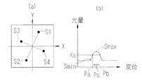
図2(a)は、ある度数の被検レンズLEを測定した時の二次元受光素子4上に投影されたスポット像S1〜S4を示す図である。図2(a)のようにスポット像が二次元受光素子4により検出される場合、被検レンズLEがない時には、直進した測定光束によるスポット像が二次元受光素子4上に投影される。これに対し、プラス度数を持った被検レンズLEが置かれると、スポット像同士の間隔が被検レンズLEの無い場合に比べて小さくなって二次元受光素子4に投影される。逆に、マイナス度数を持った被検レンズが置かれると、スポット像同士の間隔が被検レンズLEの無い場合に比べて大きくなって二次元受光素子4上に投影される。また、乱視度数を持った被検レンズLEが置かれると、所定の乱視軸角度に応じて傾斜したスポット像が投影される。   FIG. 2A is a diagram showing spot images S1 to S4 projected on the two-dimensional light receiving element 4 when the lens LE having a certain frequency is measured. When the spot image is detected by the two-dimensional light receiving element 4 as shown in FIG. 2A, when there is no test lens LE, the spot image by the measurement light beam traveling straight is projected onto the two-dimensional light receiving element 4. On the other hand, when the test lens LE having a plus power is placed, the distance between the spot images becomes smaller than that in the case where the test lens LE is not provided, and is projected onto the two-dimensional light receiving element 4. On the contrary, when a test lens having a minus power is placed, the interval between the spot images is larger than that when there is no test lens LE, and is projected onto the two-dimensional light receiving element 4. Further, when the test lens LE having the astigmatism power is placed, a spot image inclined according to a predetermined astigmatism axis angle is projected.

制御部10は二次元受光素子4によって検出されたスポット像の位置を算出する。図2(b)は、スポット像が受光素子に検出された時の受光光量の変化を示す図である。まず、制御部10は、受光光量の立ち上がり位置Sminを求め、次に、立ち上がり位置Sminから所定レベル増加した光量Ksにおける二次元受光素子4上の変位Paを求める。さらに、制御部10は、受光光量のピークSmaxを過ぎて、再び光量Ksとなった時の二次元受光素子4上の変位Pbを求める。そして、変位Paと変位Pbの中間点が二次元受光素子4上のスポット像の位置Psとなる。この時、どんな度数の被検レンズを測定しても、ほぼ一定の受光光量で、ほぼ同じ大きさのスポット像が結像するので、スポット像の位置検出精度が安定する。   The control unit 10 calculates the position of the spot image detected by the two-dimensional light receiving element 4. FIG. 2B is a diagram illustrating a change in the amount of received light when a spot image is detected by the light receiving element. First, the control unit 10 obtains the rising position Smin of the received light amount, and then obtains the displacement Pa on the two-dimensional light receiving element 4 at the light amount Ks increased by a predetermined level from the rising position Smin. Further, the control unit 10 obtains the displacement Pb on the two-dimensional light receiving element 4 when the light amount Ks is passed again after the peak Smax of the received light amount. An intermediate point between the displacement Pa and the displacement Pb is the position Ps of the spot image on the two-dimensional light receiving element 4. At this time, no matter how many times the lens to be measured is measured, a spot image of almost the same size is formed with a substantially constant received light quantity, so that the position detection accuracy of the spot image is stabilized.

制御部10は、二次元受光素子4で検出されるスポット像S1〜S4の位置を算出した後、スポット像S1〜S4の位置関係に基づいて、球面屈折力、柱面屈折力、乱視軸角度等の光学特性を求める。よって、以上のような構成によって被検レンズの光学特性を測定すれば、どんな度数の被検レンズを測定しても、一定の測定精度を保つことができ、測定精度を安定させることができる。また、異なる度数の被検レンズLEを測定する場合も、測定光束が被検レンズLEに入射する位置が同じであるので、度数によらず常に同じ位置で測定が可能である。   After calculating the positions of the spot images S1 to S4 detected by the two-dimensional light receiving element 4, the control unit 10 calculates the spherical refractive power, the columnar refractive power, and the astigmatic axis angle based on the positional relationship of the spot images S1 to S4. The optical characteristics such as are obtained. Therefore, if the optical characteristics of the test lens are measured with the above-described configuration, a constant measurement accuracy can be maintained regardless of the frequency of the test lens, and the measurement accuracy can be stabilized. Further, when measuring the test lens LE having different powers, the measurement light beam is incident on the test lens LE at the same position, so that the measurement can always be performed at the same position regardless of the power.

なお、図1に示した投光光学系19では、光源1の数は4つとしたが、光軸L1を中心に少なくとも3つの光源を設ければ、球面度数の他、乱視度数等を測定することができる。   In the light projecting optical system 19 shown in FIG. 1, the number of the light sources 1 is four. However, when at least three light sources are provided around the optical axis L1, the astigmatism power and the like are measured in addition to the spherical power. be able to.

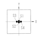
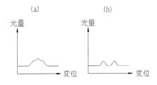
次に、図1に示した光学系及び制御系を備えるレンズメータにおいて、可変絞り2の絞りの径を変える時の動作について説明する。図3は、測定する被検レンズLEが高度数のプラスレンズである場合の、二次元受光素子4上に形成されたスポット像S1〜S4を示す図である。高度数のプラスレンズの測定では、図3のようにスポット像同士が密集しすぎてスポット像同士が重なりあってしまうことがある。このような場合、二次元受光素子4上のスポット像S1及びS2による受光光量の変化は図4(a)のようになり、制御部10では二つのスポット像として位置検出を行うことができずに測定精度が低下する。そこで、制御部10により光源1を点灯した時に二次元受光素子4からの出力信号に基づいてスポット像S1〜S4まで4つ全て検出されず、スポット像が3つ以下と判定された時には、制御部10は絞り駆動部11を駆動させることにより可変絞り2の絞りの径を小さくする。可変絞り2の絞りの径を小さくすると、二次元受光素子4上のスポット像サイズが小さくなる。図4(b)は、可変絞り2の絞りの径を小さくした時のスポット像S1及びS2による受光光量の変化を示す図である。このような状態となれば、制御部10は分離した各スポット像をそれぞれ検出でき、それぞれのスポット像の位置検出を行うことができるようになる。そして、制御部10はスポット像S1〜S4の位置を算出し、スポット像S1〜S4の位置関係に基づいて被検レンズLEの光学特性を測定する。   Next, an operation when changing the diameter of the aperture of the variable aperture 2 in the lens meter including the optical system and the control system shown in FIG. 1 will be described. FIG. 3 is a diagram showing spot images S1 to S4 formed on the two-dimensional light receiving element 4 when the test lens LE to be measured is a plus lens having an altitude number. In the measurement of an altitude plus lens, spot images may be too dense as shown in FIG. 3, and the spot images may overlap each other. In such a case, the change in the amount of received light by the spot images S1 and S2 on the two-dimensional light receiving element 4 is as shown in FIG. 4A, and the controller 10 cannot detect the position as two spot images. However, the measurement accuracy decreases. Accordingly, when the light source 1 is turned on by the control unit 10, all four spot images S <b> 1 to S <b> 4 are not detected based on the output signal from the two-dimensional light-receiving element 4. The unit 10 drives the aperture driving unit 11 to reduce the aperture diameter of the variable aperture 2. When the diameter of the diaphragm of the variable diaphragm 2 is reduced, the spot image size on the two-dimensional light receiving element 4 is reduced. FIG. 4B is a diagram showing the change in the amount of received light by the spot images S1 and S2 when the diameter of the variable diaphragm 2 is reduced. If it will be in such a state, the control part 10 will each be able to detect each isolate | separated spot image, and can detect the position of each spot image now. And the control part 10 calculates the position of spot image S1-S4, and measures the optical characteristic of the to-be-tested lens LE based on the positional relationship of spot image S1-S4.

以上のような構成とすれば、高度数のプラスレンズを測定した場合においても、測定精度を下げることなく測定を行うことができる。但し、制御部10にてスポット像が3つ以下と検出されてから可変絞り2の絞りの径を小さくしても、スポット像の分離が検出されなかった場合には、制御部10は傷や汚れによるものだと判定する。   With the above configuration, even when a plus lens having a high altitude is measured, measurement can be performed without reducing measurement accuracy. However, if separation of the spot image is not detected even if the diameter of the aperture of the variable aperture 2 is reduced after the control unit 10 detects that there are three or less spot images, the control unit 10 Judged to be due to dirt.

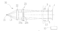
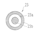
図5は、本発明に係るレンズメータの変容例の光学系及び制御系を示す図である。30は被検レンズLEに測定光束を投光する投光光学系であり、順に、測定光源21、コリメータレンズ22、リングレンズ23により構成されている。光源21は測定光軸L1上に配置され測定光束を投射する。コリメータレンズ22は光源21から投射された光束を平行光束へ変換する。リングレンズ23は、図5及び図6に示すように平板上に円筒レンズをリング状に形成したレンズ部23aと、このレンズ部23a以外に遮光のためのコーティングを施した遮光部23bより構成されている。遮光部23bによりリング状開口が形成される。なお、リング状開口を持つ遮光部23bは、レンズ部23aの近傍に別部材で構成してもよい。被検レンズLE側には、被検レンズLEを載置するためのノーズピース5、e線(546.07nm)付近のみのを通過させるバンドパスフィルタ6、2次元受光素子4が順に配置されている。ここで、コリメータレンズ22及びリングレンズ23からな投光レンズ系は、光源21とノーズピース5上に配置される被検レンズLE付近とが共役関係となるように配置されている。   FIG. 5 is a diagram showing an optical system and a control system of a modification example of the lens meter according to the present invention. Reference numeral 30 denotes a light projecting optical system for projecting a measurement light beam onto the lens LE to be measured, which is composed of a measurement light source 21, a collimator lens 22, and a ring lens 23 in this order. The light source 21 is disposed on the measurement optical axis L1 and projects a measurement light beam. The collimator lens 22 converts the light beam projected from the light source 21 into a parallel light beam. As shown in FIGS. 5 and 6, the ring lens 23 includes a lens portion 23a in which a cylindrical lens is formed in a ring shape on a flat plate, and a light shielding portion 23b in which a coating for light shielding is applied in addition to the lens portion 23a. ing. A ring-shaped opening is formed by the light shielding portion 23b. In addition, you may comprise the light-shielding part 23b with a ring-shaped opening by another member in the vicinity of the lens part 23a. On the test lens LE side, a nosepiece 5 for mounting the test lens LE, a bandpass filter 6 for passing only near the e-line (546.07 nm), and a two-dimensional light receiving element 4 are sequentially arranged. . Here, the light projecting lens system including the collimator lens 22 and the ring lens 23 is arranged so that the light source 21 and the vicinity of the lens LE to be measured arranged on the nosepiece 5 have a conjugate relationship.

光源21からの光は、コリメータレンズ22、リングレンズ23を介してリング状光束に制限されると共に、投光レンズ系(コリメータレンズ22及びリングレンズ23)の集光作用によって、ノーズピース5に載置された被検レンズLEの位置で集光する。投光レンズ系によって光源1と被検レンズLEの位置とを共役関係としたことにより、被検レンズLEはフィールドレンズが配置される場合と同じ位置になるので、被検レンズの度数の影響を受けずに、二次元受光素子4上にほぼ一定の光量で、外径と内径の幅がほぼ一定のリングパターン像ができる。   The light from the light source 21 is limited to a ring-shaped light beam through the collimator lens 22 and the ring lens 23 and is mounted on the nosepiece 5 by the condensing action of the light projecting lens system (the collimator lens 22 and the ring lens 23). The light is collected at the position of the placed lens LE. Since the light projecting lens system has a conjugate relationship between the light source 1 and the position of the test lens LE, the test lens LE is in the same position as when the field lens is arranged. Without being received, a ring pattern image can be formed on the two-dimensional light receiving element 4 with a substantially constant light amount and a substantially constant width between the outer diameter and the inner diameter.

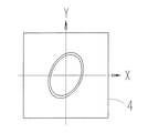
図7は、ある度数の被検レンズLEを測定した時の二次元受光素子4上に投影されたリングパターン像を示す図である。このようにリングパターン像が二次元受光素子4により検出される場合、被検レンズLEがない時には、直進した測定光束によるリングパターン像が二次元受光素子4に投影される。これに対し、プラス度数を持った被検レンズLEが置かれると、二次元受光素子4上のリングパターン像は小さくなる。逆に、マイナス度数を持った被検レンズが置かれると、二次元受光素子4上のリングパターン像は大きくなる。乱視度数を持った被検レンズLEが置かれると、リングパターン像が楕円形状となる。したがって、リングパターン像の形状を解析することにより、レンズLEの光学特性が求められる。このとき、被検レンズの度数に拘わらず、ほぼ一定の受光光量で、外径と内径の幅が一定のリングパターン像となるので、その位置検出精度が安定する。   FIG. 7 is a diagram showing a ring pattern image projected on the two-dimensional light receiving element 4 when the lens LE having a certain frequency is measured. When the ring pattern image is detected by the two-dimensional light receiving element 4 in this way, when there is no lens LE to be measured, the ring pattern image by the measurement light beam traveling straight is projected onto the two-dimensional light receiving element 4. On the other hand, when the test lens LE having a plus power is placed, the ring pattern image on the two-dimensional light receiving element 4 becomes small. Conversely, when a lens to be tested having a negative power is placed, the ring pattern image on the two-dimensional light receiving element 4 becomes large. When the test lens LE having astigmatism power is placed, the ring pattern image becomes elliptical. Therefore, the optical characteristics of the lens LE are obtained by analyzing the shape of the ring pattern image. At this time, a ring pattern image having a constant outer diameter and inner diameter width is obtained with a substantially constant amount of received light regardless of the power of the lens to be measured, so that the position detection accuracy is stabilized.

なお、上記変容例の投光光学系30において、リングレンズ23の代わりに、図8のようなマスク板40のスポット状の開口部に収束レンズ40aを設け、収束レンズ40a周辺を遮光部40bとしたものを配置してもよい。このような構成においても、レンズ40aを介して測定光束が4つのスポット状光束となり、レンズ40aの集光作用によって被検レンズLEの位置で集光し、受光素子4上のスポット像サイズは、どんな度数の被検レンズであっても変わらなくなる。なお、リングレンズ23は、スポット状の開口部と収束レンズ40aとを光軸L1を中心に多数配置した構成と見なすことができ、この場合も少なくとも3つの測定光束を投光する投光光学系30に含まれるものである。   In the projection optical system 30 of the above modification example, instead of the ring lens 23, a converging lens 40a is provided in a spot-like opening of a mask plate 40 as shown in FIG. You may arrange what you did. Even in such a configuration, the measurement light beam becomes four spot-like light beams through the lens 40a, and is condensed at the position of the test lens LE by the condensing action of the lens 40a. The spot image size on the light receiving element 4 is It does not change regardless of the power of the test lens. Note that the ring lens 23 can be regarded as a configuration in which a large number of spot-shaped openings and converging lenses 40a are arranged around the optical axis L1, and in this case also, a projection optical system that projects at least three measurement light beams 30.

本実施例におけるレンズメータの光学系及び制御系を示す概略構成図である。It is a schematic block diagram which shows the optical system and control system of the lens meter in a present Example. ある度数の被検レンズを測定した時の二次元受光素子上に投影されたスポット像を示す図、及びスポット像が受光素子に検出された時の受光光量の変化を示す図である。It is a figure which shows the spot image projected on the two-dimensional light receiving element at the time of measuring a certain test lens, and a figure which shows the change of the received light quantity when a spot image is detected by the light receiving element. 被検レンズが高度数のプラスレンズである場合の二次元受光素子上に形成されたスポット像を示す図である。It is a figure which shows the spot image formed on the two-dimensional light receiving element in case a to-be-tested lens is an altitude number plus lens. スポット像同士が重なりあった時の二次元受光素子上のスポット像S1及びS2による受光光量の変化を示す図、及び各スポット像が分離された時のスポット像S1及びS2による受光光量の変化を示す図である。The figure which shows the change of the received light quantity by spot image S1 and S2 on a two-dimensional light receiving element when spot images overlap, and the change of the received light quantity by spot image S1 and S2 when each spot image is isolate | separated. FIG. 本発明に係るレンズメータの変容例の光学系及び制御系を示す図である。It is a figure which shows the optical system and control system of the modification example of the lens meter which concerns on this invention. リングレンズの構成を説明するための図である。It is a figure for demonstrating the structure of a ring lens. ある度数の被検レンズLEを測定した時の二次元受光素子上に投影されたリングパターン像を示す図である。It is a figure which shows the ring pattern image projected on the two-dimensional light receiving element when measuring the lens LE of a certain frequency. スポット状の開口部に収束レンズが設けられたマスク板の構成を説明するための図である。It is a figure for demonstrating the structure of the mask board in which the convergence lens was provided in the spot-shaped opening part.

符号の説明Explanation of symbols

1 測定光源
2 可変絞り
3 投光レンズ
4 2次元受光素子
5 ノーズピース
10 制御部
11 絞り駆動部
LE 被検レンズ
S1〜S4 スポット像
L1 光軸
21 光源
22 コリメータレンズ
23 リングレンズ
40 マスク板


DESCRIPTION OF SYMBOLS 1 Measurement light source 2 Variable aperture 3 Light projection lens 4 Two-dimensional light receiving element 5 Nosepiece 10 Control part 11 Aperture drive part LE Test lens S1-S4 Spot image L1 Optical axis 21 Light source 22 Collimator lens 23 Ring lens 40 Mask board


Claims (4)

被検レンズを所定の位置に載置するためのノーズピースと、測定光源からの測定光束を被検レンズへ投光する投光レンズ系を持ち、被検レンズに対して少なくとも3つの測定光束を投光する投光光学系と、被検レンズを透過した後の測定光束を結像光学系を介さずに受光する位置に配置された2次元受光素子とを備え、前記2次元受光素子の出力に基づいて被検レンズの光学特性を測定するレンズメータであって、前記投光レンズ系は、前記測定光源とノーズピースに載置される被検レンズ付近とが共役関係となるように配置されていることを特徴とするレンズメータ。 It has a nosepiece for placing the test lens at a predetermined position, and a projection lens system for projecting the measurement light beam from the measurement light source to the test lens, and at least three measurement light beams are applied to the test lens. A light projecting optical system for projecting light, and a two-dimensional light receiving element disposed at a position for receiving the measurement light beam after passing through the test lens without passing through the imaging optical system, the output of the two-dimensional light receiving element The projection lens system is arranged so that the measurement light source and the vicinity of the test lens placed on the nosepiece are in a conjugate relationship. A lens meter characterized by 請求項1のレンズメータにおいて、前記投光光学系は前記測定光源と投光レンズ系との間に配置され、且つ前記投光レンズ系の像側焦点位置に配置された絞りを備え、前記測定光源は少なくとも3個配置されていることを特徴とするレンズメータ。 2. The lens meter according to claim 1, wherein the light projecting optical system includes a stop disposed between the measurement light source and the light projecting lens system, and disposed at an image side focal position of the light projecting lens system. A lens meter, wherein at least three light sources are arranged. 請求項2のレンズメータにおいて、前記絞りの径を変化させる絞り径可変手段と、前記2次元受光素子の出力に基づいて前記絞り径可変手段を制御する制御手段と、を備えることを特徴とするレンズメータ。 3. The lens meter according to claim 2, further comprising: aperture diameter variable means for changing the diameter of the diaphragm; and control means for controlling the aperture diameter variable means based on an output of the two-dimensional light receiving element. Lens meter. 請求項1の投光レンズ系は、コリメータレンズと、該コリメータレンズを通過した前記測定光源からの光をリング状に制限して被検レンズに集光するリングレンズと、を持つことを特徴とするレンズメータ。


The light projecting lens system according to claim 1 has a collimator lens, and a ring lens that condenses the light from the measurement light source that has passed through the collimator lens in a ring shape and focuses the light on the lens to be examined. Lens meter to do.


JP2004106805A 2004-03-31 2004-03-31 Lens meter Pending JP2005291901A (en)

Priority Applications (1)

Application Number Priority Date Filing Date Title
JP2004106805A JP2005291901A (en) 2004-03-31 2004-03-31 Lens meter

Applications Claiming Priority (1)

Application Number Priority Date Filing Date Title
JP2004106805A JP2005291901A (en) 2004-03-31 2004-03-31 Lens meter

Publications (1)

Publication Number Publication Date
JP2005291901A true JP2005291901A (en) 2005-10-20

Family

ID=35324990

Family Applications (1)

Application Number Title Priority Date Filing Date
JP2004106805A Pending JP2005291901A (en) 2004-03-31 2004-03-31 Lens meter

Country Status (1)

Country Link
JP (1) JP2005291901A (en)

Cited By (1)

* Cited by examiner, † Cited by third party
Publication number Priority date Publication date Assignee Title
CN110806307A (en) * 2019-11-19 2020-02-18 中国兵器装备集团自动化研究所 Method for rapidly detecting stability precision of photoelectric sight-stabilizing system

Cited By (1)

* Cited by examiner, † Cited by third party
Publication number Priority date Publication date Assignee Title
CN110806307A (en) * 2019-11-19 2020-02-18 中国兵器装备集团自动化研究所 Method for rapidly detecting stability precision of photoelectric sight-stabilizing system

Similar Documents

Publication Publication Date Title
US10634582B2 (en) Lens characteristic evaluation device and method of operating lens characteristic evaluation device
JP5084327B2 (en) Eccentricity inspection device and eccentricity adjustment device
JP2005291900A (en) Lens meter
CN101424568A (en) Light measuring device and scanning optical system
JP2009300257A (en) Optical system for measurement
JP2005315654A (en) Lens meter
JP2005241605A (en) Lens meter
JP4458937B2 (en) Eye refractive power measuring device
TWI699510B (en) Increasing dynamic range of a height sensor for inspection and metrology
JP2005291901A (en) Lens meter
KR20050099475A (en) Lens meter
JP4683270B2 (en) Lens meter
KR101487251B1 (en) Optical tracking system and method for tracking using the same
JP2008026049A (en) Flange focal length measuring device
JP2003207323A (en) Optical displacement measuring instrument
JP2001166202A (en) Focus detection method and focus detector
JP2013148437A (en) Focus detection device, wavefront aberration measurement device and lens manufacturing method
JP2004085442A (en) Displacement measuring apparatus
JP2007240168A (en) Inspection device
JP2012229983A (en) Displacement sensor
JP2001188030A (en) Lens meter
CN213456056U (en) Detection assembly and detection device
JP2012149984A (en) Displacement detecting deice, exposure device, and device manufacturing method
JPH11304640A (en) Optical element inspection device
JPH0471453B2 (en)